Forum sponsored by:

Stepper power for autofeed on lathe
| Phil Grant | 09/10/2018 20:46:50 |
| 107 forum posts 21 photos | Hi, Been having a read through the forum as research for adding a stepper motor to my Warco super mini lathe autofeed. It looks like the kit Myfordby uses in his youtube video is favourite at the moment. I've designed and made a bracket to replace the gears at the end of the lathe using a Nema 23 stepper motor and I was wondering if anyone has a suggestion as to the power needed for the stepper, is 3Nm OK or too much. I've fettled the leadscrew mounts and it turns freely by hand with no load but not sure what sort of torque will be required when cutting. I'm using a stepper motor with a simple speed control at first but looking to add an arduino into the mix later for thread cutting and maybe adding another stepper to the cross feed later to dabble in a CNC conversion maybe...... Thanks for any help. |
| not done it yet | 09/10/2018 21:19:25 |
| 7517 forum posts 20 photos | Feed rate for surface cutting is one thing, but advancing 2.5mm per spindle revolution may need rather more power, I would guess? Not thought whether 3Nm is enough or too much. |
| John Haine | 09/10/2018 22:22:17 |
| 5563 forum posts 322 photos | The Z feed for my Super7 CNC conversion uses a type AC5707645251 size 23 stepper motor that came from Arc Euro Trade (I think they no longer stock these). Googling it says that it's rated torque is 180Ncm - what a ragbag of units! But that's 1.8 Nm. There's a 2:1 toothed belt reduction between motor and leadscrew. I have never had a problem with inadequate torque either surfacing or screwcutting. The leadscrew pitch is 1/8" so slightly larger than yours. I can't see why more torque would be a problem? The driver is the ubiquitous 2m541 type, also from Arc, supply ~40V and probably running peak current of 2.5A or so. |
| Phil Grant | 09/10/2018 22:56:22 |
| 107 forum posts 21 photos | Posted by John Haine on 09/10/2018 22:22:17:
The Z feed for my Super7 CNC conversion uses a type AC5707645251 size 23 stepper motor that came from Arc Euro Trade (I think they no longer stock these). Googling it says that it's rated torque is 180Ncm - what a ragbag of units! But that's 1.8 Nm. There's a 2:1 toothed belt reduction between motor and leadscrew. I have never had a problem with inadequate torque either surfacing or screwcutting. The leadscrew pitch is 1/8" so slightly larger than yours. I can't see why more torque would be a problem? The driver is the ubiquitous 2m541 type, also from Arc, supply ~40V and probably running peak current of 2.5A or so. Thanks for the info. |
| Phil Grant | 21/10/2018 11:20:22 |
| 107 forum posts 21 photos | Hi, Went for one of these in the end **LINK** with a DM542T controller and 24V power supply direct from stepperonline delivered from the UK. Quite reasonably priced and delivered in a few days. Got it all on the bench working with an Arduino using Accelstepper library. Got to get some sort of user interface together then attach it to the lathe. |
| Muzzer | 21/10/2018 11:36:30 |
 2904 forum posts 448 photos | Most of the hobby people just go on the basis of what others have found to work. The reason being that it's not easy to measure or estimate the required torque and speed extremes. And even then, to describe a stepper as "1.8Nm" is often unhelpful. I doubt if many of them could actually muster that level of torque to begin with - and it falls off very rapidly with speed. You'll notice that the Chinese outfit you used also sell clones of the Leadshine "integrated easy servo" stepper motors. These combine the stepper driver module into the motor, along with an encoder on the motor shaft. This requires a lot less messing about to connect up the driver (just provide the step/dir signals and DC power) and being closed loop, it won't suffer from lost steps and can recover from a temporary overload. That's many of the advantages of a true servo with the cost of a stepper - and no external amp / driver, cleaner wiring etc. That additional level of control robustness means you don't need such a large margin of safety on the torque to guard against loss of position. Incidentally, as the torque from a stepper motor drops off roughly proportional to speed, there is usually no advantage in creating a step-down reduction by using gears or pulleys. The effect of such a reduction is to make the motor run at twice the speed - and about half the torque. The net result is simply a reduction in the maximum speed of the output shaft, which is a problem for stepper motors to begin with. You are generally better off driving the leadscrews directly with steppers. Murray
|
| Martin Connelly | 21/10/2018 12:47:59 |
 2549 forum posts 235 photos | I use small Leadshine hybrids on my lathe. I do have a timing belt drive though because I spin the nut to push and pull the lead screw attached to the saddle. The driven pulley is threaded onto a bush that fits into a pair of flanged bearings and allows backlash elimination by squeezing down on the two bearings that sandwich a fixed plate between them. The reason for this system is that it allows modification with minimal change on the lathe so it can be reverted to manual if required. The downside is that you need to allow for a leadscrew sticking out of the tailstock end. If you are not after rapid motions a large motor is overkill. Hobby use is not usually looking to shave seconds off a job. Martin C |
| SillyOldDuffer | 21/10/2018 12:56:18 |
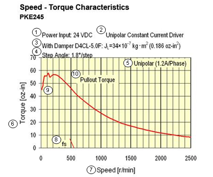
| 10668 forum posts 2415 photos | Posted by Muzzer on 21/10/2018 11:36:30: ... Incidentally, as the torque from a stepper motor drops off roughly proportional to speed, there is usually no advantage in creating a step-down reduction by using gears or pulleys. The effect of such a reduction is to make the motor run at twice the speed - and about half the torque. The net result is simply a reduction in the maximum speed of the output shaft, which is a problem for stepper motors to begin with. You are generally better off driving the leadscrews directly with steppers. Murray
I love this forum! Thanks to Murray, I realised my understanding of steppers was adrift re their relationship to gearing and did some emergency googling. I found this graph with description here which is illustrative as an example.
Very educational. Ta Dave |
| Martin Connelly | 21/10/2018 13:17:10 |
2549 forum posts 235 photos | I don't think that graph applies to hybrid stepper systems. They are supposed to have superior dynamic torque compared to standard stepper motors. Martin C Edited By Martin Connelly on 21/10/2018 13:24:50 |
| Martin Connelly | 21/10/2018 13:22:38 |
2549 forum posts 235 photos |
This is how I have my lathe set up for the Z axis drive. The leadscrew is 16mm if you are wondering about sizes. The leadscrew connects to a plain rod to push/pull the carriage. This type of setup also allows for testing the drive torque with minimal changes to the lathe if you are experimenting with different systems. Martin C |
| Phil Grant | 23/10/2018 22:27:41 |
| 107 forum posts 21 photos | Getting to grips with the Arduino controlling the stepper motor, waiting for some parts to mount it on the lathe but in the meantime I designed and 3D printed an end cover with cable management to fit with the flexible plastic tubing I have for protecting the cables. If anyone is interested I can post the STL file on Thingiverse.
|
| Phil Grant | 29/09/2019 11:16:36 |
| 107 forum posts 21 photos | Just an update on my powered feed project, I came across this video on Youtube I bought the TI LaunchPad board and designed my own, through hole, PCB for the interface and am just waiting for the PCBs to arrive. Edited By Phil Grant on 29/09/2019 11:17:19 |
| Brian Oldford | 30/09/2019 12:43:32 |
 686 forum posts 18 photos | Posted by Phil Grant on 29/09/2019 11:16:36:
Just an update on my powered feed project, I came across this video on Youtube I bought the TI LaunchPad board and designed my own, through hole, PCB for the interface and am just waiting for the PCBs to arrive. Edited By Phil Grant on 29/09/2019 11:17:19 That's the system I'm currently in the process of fitting to my S7. I doing the mechanicals at present. I'm hoping a **LINK** driving through a pair of 1:1 skew gears will be sufficiently powerful. |
| Phil Grant | 30/09/2019 13:06:28 |
| 107 forum posts 21 photos | I did my own PCBs as they are very cheap to get made in China and I don't want the hassle of doing surface mount, the boards will probably be cheaper than just the postage to cover the boards from the states. I used a 2.8Nm NMEA23 stepper mounted direct to the leadscrew on my mini WARCO lathe and although I've not done any threads yet is works fine as a power feed driven from an Arduino.
|
| Brian Oldford | 30/09/2019 15:46:52 |
686 forum posts 18 photos | Posted by Phil Grant on 30/09/2019 13:06:28:
I did my own PCBs as they are very cheap to get made in China and I don't want the hassle of doing surface mount, the boards will probably be cheaper than just the postage to cover the boards from the states. I used a 2.8Nm NMEA23 stepper mounted direct to the leadscrew on my mini WARCO lathe and although I've not done any threads yet is works fine as a power feed driven from an Arduino.
How many did you have made? What sort of price were they? |
| Phil Grant | 30/09/2019 19:07:32 |
| 107 forum posts 21 photos | Around £10 ish for 10 off. Ignore the strange blocks, there were no shapes stored against these parts so Fusion adds an appropriately sized box.
Edited By Phil Grant on 30/09/2019 19:09:45 Edited By Phil Grant on 30/09/2019 19:10:48 |
| Phil Grant | 30/09/2019 20:50:17 |
| 107 forum posts 21 photos | Just noticed I published an image of the board showing two power LEDs, these are not on the PCBs I ordered and am waiting for, this would be a version 2 if required. |
| Phil Grant | 30/09/2019 20:52:42 |
| 107 forum posts 21 photos | Just printed a bracket to mount the optical encoder onto the lathe |
| Phil Grant | 01/10/2019 21:59:32 |
| 107 forum posts 21 photos | PCBs
|
| Phil Grant | 20/10/2019 08:35:03 |
| 107 forum posts 21 photos | The final PCBs arrived yesterday for the Electronic leadscrew project from Clough42.. t powered up and worked fine, There are spaces for the eeprom and two power LEDs, 5V and 3.3V but I haven't populated them as it will be inside a box and not visible. I also changed the power socket to a surface mount one because it sits overs some header pins on the host board.
Edited By Phil Grant on 20/10/2019 08:36:14 Edited By Phil Grant on 20/10/2019 09:20:01 |


Please login to post a reply.
Magazine Locator
Want the latest issue of Model Engineer or Model Engineers' Workshop? Use our magazine locator links to find your nearest stockist!
Sign up to our Newsletter
Sign up to our newsletter and get a free digital issue.
You can unsubscribe at anytime. View our privacy policy at www.mortons.co.uk/privacy
Latest Forum Posts
- *Oct 2023: FORUM MIGRATION TIMELINE*
05/10/2023 07:57:11 - Making ER11 collet chuck
05/10/2023 07:56:24 - What did you do today? 2023
05/10/2023 07:25:01 - Orrery
05/10/2023 06:00:41 - Wera hand-tools
05/10/2023 05:47:07 - New member
05/10/2023 04:40:11 - Problems with external pot on at1 vfd
05/10/2023 00:06:32 - Drain plug
04/10/2023 23:36:17 - digi phase converter for 10 machines.....
04/10/2023 23:13:48 - Winter Storage Of Locomotives
04/10/2023 21:02:11 - More Latest Posts...
- View All Topics
Support Our Partners


Shopping Partners
Subscription Offer

Latest "For Sale" Ads
- Reeves** - Rebuilt Royal Scot by Martin Evans
by John Broughton
£300.00 - BRITANNIA 5" GAUGE James Perrier
by Jon Seabright 1
£2,500.00 - Drill Grinder - for restoration
by Nigel Graham 2
£0.00 - WARCO WM18 MILLING MACHINE
by Alex Chudley
£1,200.00 - MYFORD SUPER 7 LATHE
by Alex Chudley
£2,000.00 - More "For Sale" Ads...
Latest "Wanted" Ads
- D1-3 backplate
by Michael Horley
Price Not Specified - fixed steady for a Colchester bantam mark1 800
by George Jervis
Price Not Specified - lbsc pansy
by JACK SIDEBOTHAM
Price Not Specified - Pratt Burnerd multifit chuck key.
by Tim Riome
Price Not Specified - BANDSAW BLADE WELDER
by HUGH
Price Not Specified - More "Wanted" Ads...
Get In Touch!
Do you want to contact the Model Engineer and Model Engineers' Workshop team?
You can contact us by phone, mail or email about the magazines including becoming a contributor, submitting reader's letters or making queries about articles. You can also get in touch about this website, advertising or other general issues.
Click THIS LINK for full contact details.
For subscription issues please see THIS LINK.
Digital Back Issues


Donate

 Register
 Log-in
Model Engineer Magazine
- Percival Marshall
- M.E. History
- LittleLEC
- M.E. Clock

ME Workshop
- An Adcock
- & Shipley
- Horizontal
- Mill

Subscribe Now
- Great savings
- Delivered to your door

Pre-order your copy!
- Delivered to your doorstep!
- Free UK delivery!
All Forum Topics > CNC machines, Home builds, Conversions, ELS, automation, software, etc tools > Stepper power for autofeed on lathe