Forum sponsored by:

Rotary table set up
| BOB BLACKSHAW | 27/06/2018 20:58:53 |
| 501 forum posts 132 photos | I am thinking of making some type of jig to set up a rotary table on a mill. I thought of using a plunge DTI on a lump of aluminum bolted to the rotary table so that it rests on the mill spindle. How do you set up a rotary table, as in the past its taken me ages to get a reasonable set up. If this has been discussed in past threads, apologies to all. Bob. |
| Mike Clarke | 27/06/2018 21:08:26 |
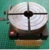 95 forum posts 2 photos | Hi Bob, I use a large ball bearing (approx 30mm) - lower the quill and trap the ball bearing between the centre of the rotary table (presuming you have a hole there!) and your milling chuck, for example. Works for me. Cheers, Mike |
| Maurice | 27/06/2018 21:11:12 |
| 469 forum posts 50 photos | I assume that you wish to set the centre of the rotary table in line with the axis of the mill spindle. I use a morse tapered mandrel with an accurate 1/4” reamed hole in it, and a length of 1/4” sliding in it with a circling to stop it falling right out. A piece of steel is fitted in the centre of the rotary table, also with a 1/4” hole reamed in it. Having clamped the rotary table approximately under the spindle, then move the mill table until the rod drops freely into the hole. If in any doubt, check it after with a DTI. Maurice |
| mark costello 1 | 27/06/2018 22:03:57 |
 800 forum posts 16 photos | Excellent,Mike. |
| Andrew Johnston | 27/06/2018 22:27:50 |
 7061 forum posts 719 photos | Step 1: Set, and lock, the rotary table on zero. Step 2: Lightly bolt down the rotary table, indicate on one of the four slots while moving the appropriate table axis. Tap the rotary table to reduce indicator movement, when the indicator doesn't move tighten the bolts. Step 3: Use one of these:
in conjunction with the parallel hole in the centre of the rotary table to set the DRO on 0,0. For those who don't recognise the unit it's a Haimer Centro. Having completed all steps the rotary table will have its cardinal points aligned with the X and Y movements of the mill, and the DRO indicates the centre of the rotary table. Doesn't take long, probably a few minutes. Andrew Edited By Andrew Johnston on 27/06/2018 22:28:16 |
| DMB | 27/06/2018 23:28:15 |
| 1585 forum posts 1 photos | Alright for those able to boast about such large balls. Sorry, couldn't resist that. Where's me coat? |
| Jim Nic | 27/06/2018 23:45:31 |
 406 forum posts 235 photos | I use a 2MT mandrel in the centre of the rotary table as per Maurice, albeit with a 10mm rod. I loosely position the rotary table on the mill table with the rod inserted in the mandrel then tighten it down. Jim |

Please login to post a reply.
Magazine Locator
Want the latest issue of Model Engineer or Model Engineers' Workshop? Use our magazine locator links to find your nearest stockist!
Sign up to our Newsletter
Sign up to our newsletter and get a free digital issue.
You can unsubscribe at anytime. View our privacy policy at www.mortons.co.uk/privacy
Latest Forum Posts
- *Oct 2023: FORUM MIGRATION TIMELINE*
05/10/2023 07:57:11 - Making ER11 collet chuck
05/10/2023 07:56:24 - What did you do today? 2023
05/10/2023 07:25:01 - Orrery
05/10/2023 06:00:41 - Wera hand-tools
05/10/2023 05:47:07 - New member
05/10/2023 04:40:11 - Problems with external pot on at1 vfd
05/10/2023 00:06:32 - Drain plug
04/10/2023 23:36:17 - digi phase converter for 10 machines.....
04/10/2023 23:13:48 - Winter Storage Of Locomotives
04/10/2023 21:02:11 - More Latest Posts...
- View All Topics
Support Our Partners


Shopping Partners
Subscription Offer

Latest "For Sale" Ads
- Reeves** - Rebuilt Royal Scot by Martin Evans
by John Broughton
£300.00 - BRITANNIA 5" GAUGE James Perrier
by Jon Seabright 1
£2,500.00 - Drill Grinder - for restoration
by Nigel Graham 2
£0.00 - WARCO WM18 MILLING MACHINE
by Alex Chudley
£1,200.00 - MYFORD SUPER 7 LATHE
by Alex Chudley
£2,000.00 - More "For Sale" Ads...
Latest "Wanted" Ads
- D1-3 backplate
by Michael Horley
Price Not Specified - fixed steady for a Colchester bantam mark1 800
by George Jervis
Price Not Specified - lbsc pansy
by JACK SIDEBOTHAM
Price Not Specified - Pratt Burnerd multifit chuck key.
by Tim Riome
Price Not Specified - BANDSAW BLADE WELDER
by HUGH
Price Not Specified - More "Wanted" Ads...
Get In Touch!
Do you want to contact the Model Engineer and Model Engineers' Workshop team?
You can contact us by phone, mail or email about the magazines including becoming a contributor, submitting reader's letters or making queries about articles. You can also get in touch about this website, advertising or other general issues.
Click THIS LINK for full contact details.
For subscription issues please see THIS LINK.
Digital Back Issues


Donate

 Register
 Log-in
Model Engineer Magazine
- Percival Marshall
- M.E. History
- LittleLEC
- M.E. Clock

ME Workshop
- An Adcock
- & Shipley
- Horizontal
- Mill

Subscribe Now
- Great savings
- Delivered to your door

Pre-order your copy!
- Delivered to your doorstep!
- Free UK delivery!
All Forum Topics > Help and Assistance! (Offered or Wanted) > Rotary table set up