Forum sponsored by:

Homemade collet chuck alignment issues
Not fully seating on Myford threaded spindle.
| William S | 01/05/2018 12:40:21 |
 80 forum posts 335 photos | Hello all last July we brought a homemade Myford ER32 collet chuck off of the well known auction site. It looked to be well made but was made for a early Myford as the register diameter was smaller (i believe they were smaller please correct me if I'm wrong) This didn't really worry us as we would just bore it out. Well it has sat untouched since July and having assured ourselves that the lathe was as level as we could get it, we decided to have a go at machining the collet chuck to fit our lathe. Well first we finally made the morse taper mandrel to use our tailstock die holder without a drill chuck and the original aluminium mandrel. We purchased the soft stub 2mt arbour 2+ years ago for use on the original mini lathe, but we never got around to machining it to use.
Then using the die holder mandrel the collet chuck was set up like above, this to us makes the most sense as we are turning the important bit to the actual collet taper. Also it allowed the whole assembly to be removed without being to bulky to test the fit. We did mark the 2mt mandrel so it went back in the same place each time. Boring it out was very nice, went very uneventful, no issues. Also skimmed the rear face to be perfectly square with the bore. Now here comes the problem, when the collet chuck is screwed onto the Myford spindle nose it goes on nice no tight spots all good, then when it reaches the rear alignment face only half of it actually touches it, the other half is about 0.04mm away.
The spindle has no detritus on it nor does the collet chuck. the depth of the bore is plenty, replicating our other chucks which have no issues with alignment. The collet chuck doesn't appear to be contacting any part of the spindle which it shouldn't and it always has the gap in the same place, every time it is screwed on. It does decrease the tighter it is screwed on but I'm afraid that it remain on if I attempt to tighten it up any more! None of our other chucks require much force to put them on. I would like to get the 2 surfaces to contact all the way round but I can not see what is preventing it, the only thing that may be the cause is if the thread inside is off somehow. I Accept that once these 2 surfaces are in full contact truing up the collet taper bore will ensure it is as concentric to the lathe spindle as possible. I hope that all makes sense, many thanks for reading and any ideas would be a great help William |
| David George 1 | 01/05/2018 22:20:08 |
 2110 forum posts 565 photos | Hi William did you check that the mandrel was running true with dial indicator before you used it to hold the chuck. Have you tried to blue the spindle with engineers blue to see if it mates with the spindle . David |
| Hopper | 01/05/2018 23:53:38 |
 7881 forum posts 397 photos | Also, it could be you runout in the machine set up somewhere. The internal taper in the headstock spindle quite often does not run true on old lathes. They get burred up or distorted over the years. Spindles even get slightly bent if a tooth comes off a backgear and goes through the works. Would be worth checking your spindle bore for runout. Likewise, collets can have a bit of runout, specailly cheap ones, and with that set up there is a fair bit of overhang that would amplify the error. If the collet holder was set up true when you machined it, there should have been no run out on the bore or the end face before you took a cut. Did you check that? |
| Brian Wood | 02/05/2018 08:57:41 |
| 2742 forum posts 39 photos | Hello William S, Try putting a small 45 degree chamfer on the square corner between the vertical and horizontal register faces of your new chuck so that there is no longer interference at that point on the lathe nose, it allows the lathe registers to do their job and removes the binding on the corner which is what I suspect is holding it off from fully bedding home.. Regards Brian
|
| Lambton | 02/05/2018 09:03:51 |
 694 forum posts 2 photos | William, There is a 0.031" radius between the two faces of the Myford register that is not too apparent when looking at the spindle. I had the same problem as your good self with a new chuck back plate. Just machine a chamfer just large enough to give clearance for this rad.at the back of you collet chuck. Use a fag paper to check for any looseness not engineer's blue. If the back plate or collet chuck is not hard up against the back of the register the screw thread will act as a false register. I have tried to include a copy of the drawing of the Myford spindle but have not been able to. However a copy does appear on page 3.8 of Tubal Cain's Model Engineer's Handbook. Eric |
| William S | 02/05/2018 12:35:23 |
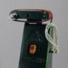
80 forum posts 335 photos | Hello all Thanks for your replies, no I did not check any face with a dial test indicator, I'm now paying the price for it!. Now that has been brought to my attention that would of made the most sense. I assumed that by turning the register bore to the collet taper would of ensured the best accuracy for our machine but in hindsight this isn't the case. It did look to run quite true before I did any machining but that is no excuse. Regarding the collets, they are the same set that we use in our mill and we have no problems with run-out there. The Myfords spindle runs within 0.02mm on both the register faces and the spindle morse taper, when the mandrel was machined it was marked and was always reinserted in the same position, so I can not see any reason for terrific run-out on that In the picture of the collet chuck it isn't apparent but there is a chamfer between the 2 register faces, albeit it was a bit small, I have just increased its size and it has appeared to make no difference. it is now slightly larger than all of our other chucks which have no issue. I have also just found out that if I lightly tap the collet chuck with the palm of my hand on the collet nut side it will close up the gap, so it appears to rock on something. when this gap is closed up the inner collet taper has about 0.07mm of run out which is a lot better than with the large gap but still isn't as precise as it should be. (I know that re-machining the taper will improve this reading but I wish to get to the bottom of the apparent rocking first). Could this apparent rocking be caused by not setting it up initially with a dial indicator, which has made the thread off slightly? Many thanks William |
| Chris Evans 6 | 02/05/2018 13:20:51 |
 2156 forum posts | The last soft nose morse taper shank I had to machine was awful with 0.015" runout. but as you have machined yours in situ it should not be a problem. I think looking at your set up you could have an accumulation of errors a thou or two here and there adding up. Some work finding out why your register is not seating should get you to a useable state. |
| HOWARDT | 02/05/2018 15:57:52 |
| 1081 forum posts 39 photos | Reduce the contact area on the face, open the bore out to leave an angular ring contact say 8mm wide from the OD. If the bore is a good fit on the spindle you have two large contact areas fighting each other. The shaft diameter length is there to support the weight and the face is something to tighten upto. |
| Brian Wood | 02/05/2018 19:07:00 |
| 2742 forum posts 39 photos | William, Your new discovery sounds like the very end of the nose thread is bottoming on a feature in your chuck. Try marking the end with a spot of paint and see if it transfers when you tap the nut end. If so take a little more out of the bore to correct it. Now that I look closely I can see the chamfer, it wasn't obvious. Regards Brian |
| Neil Lickfold | 02/05/2018 20:29:53 |
| 1025 forum posts 204 photos | When you made the ER32 holder and thread for the nut, did you try it ? So when you bored the 8 deg taper and after threading for the collet nut, did you place the collet you want to use , and place a test bar in that collet to check it's concentricity? I have found a lot of ERcollets do not hold perfectly straight and concentric, some being up to 0.1mm or more at 60mm out from the collet. But then you can actually tap the part to true, and then tighten the collet , and it will generally stay there. I found the Regofix high precision collets to be the best I have found. When making my collet blocks and extensions etc, I make the back end 1st. IE the MT2 or MT3 part , I do 1st and leave the rest of the mandrel parallel, for a sencond op reference. Then set up on the lathe spindle , like Myford, and mark an orientation position near the spindle of the new mandrel, ie to align closely to the start of the thread, for example. Then I set about making the 8 deg inner bore and finally cutting the matching thread for the collet nut. I make the collet nut thread a very good fit. So that it does screw on, but with minimal clearance. So it must always be very clean. I have afew pics of some I have made in my album. My newest one is a MT4 to ER11 holder. I have the MT4 taper done with the M16 thread. It will go into an MT4 to parallel shank holder , and have the ER11 detail turned last. When I made the ER20 to ER11 adapter, I made it in 1 piece. So ruffed out the shapes, and the finished the 8 deg tapers and the M13X1 thread, then Parted if off the piece of bar. It may be that the best way to make it right, is to start again, and do the back end 1st, and get it to locate onto the spindle correctly. Then set about making the front end of the ER32 detail, thread and 8 deg taper last. You should be able to make the register very close by either just measuring it, or by making a test bar of the same diameter as the register on the nose of your lathe. The important part is that the spindle thread that you screw cut, is concentric to the register diameter , and then face last. Making a generous corner radius on the back of the adapter is good, The register diameter does not have to be really long either. As long as the thread is concentric, it actually can be quite loose, and still function perfectly well, without causing it to be not true. One thing to do check , is the the full thread form in the adapter, does finish before the full thread form of the spindle. I measure from the shoulder to the area where the full form starts to wash out, and go another 1/2 turn further away from the spindle shoulder face. This longer distance, wants to be the minimum bore depth for the start of the Myford spindle thread in your adapter. Then make sure you have thread cut deeper than the full length of the spindle nose, or make sure the run out area (undercut thread relief) is definitely longer than the total spindle nose length. While making the back end, I would just drill a pilot hole as deep as the total length of the part, so on the second op, it is just turning and boring out. Neil |
| Nick Hulme | 04/05/2018 09:12:07 |
| 750 forum posts 37 photos | As with a chuck back plate the rear register must be correct first, then it's mounted on the spindle and the front is finished, any other way you are simply juggling with your various alignment errors and issues. |
| William S | 08/05/2018 13:55:32 |
80 forum posts 335 photos | Hello all Thanks for all of your advice and help. I found a 55 degree internal threading tool so what i shall do is to set it back up indicate the bore that I have machined to get that perfect, then set the lathe up to cut a 12 tpi thread, line the tool up with the existing thread and spin the lathe by hand to true the thread up to the bore. This is my fault for not indicating the original bore in the first place this is where I think the issues is. However, this is currently put on hold by an issue that we did not know about, our lathe in its current form can only cut 2,4,5,6,7 BA threads accurately! This was discovered when I set up an exterior threading tool, lined it up with the one of the threads on the lathe spindle, selected 12 tpi on the gearbox and then with the half nuts engaged spun the spindle by hand. It was then very clear the fact that over the threaded portion of the spindle the tool had misaligned by one thread (the tool had been retracted so was not damaging the spindle) this was traced back with the help from this thread- http://www.model-engineer.co.uk/forums/postings.asp?th=125630 the first picture with the arrow shows the gear that on our lathe is smaller, instead of the original 24 tooth gear ours is a 20 tooth. Whether this has been done intentionally or by accident we shall never know (going off of the charts lower down the linked page says that a 20 tooth gear will allow a 2,4,5,6,7 BA thread to be cut without the expensive metric change gears, we also put a 2 BA tap in the chuck and did the same procedure as described above and it lined up perfectly) So I now need to purchase a 24 tooth gear to get it back to original, If I hadn't of checked it now that collet chuck would definitely be scrap by now! I hope that makes sense Thanks again William |
| Farmboy | 08/05/2018 14:44:34 |
| 171 forum posts 2 photos | It may be an optical illusion, but in the last photo of your first post it appears that the internal thread depth to the inner shoulder is shorter than the external thread on the spindle nose. If so, the chuck will never seat properly on the register as it is seating on the shoulder first. You could check this by placing a large washer on the spindle, against the register face, before fitting the chuck to see if it then seats properly before removing any more metal. Unless the thread engagement is extremely tight it should not prevent the register faces aligning. Mike. Edited By Farmboy on 08/05/2018 14:53:00 |


Please login to post a reply.
Magazine Locator
Want the latest issue of Model Engineer or Model Engineers' Workshop? Use our magazine locator links to find your nearest stockist!
Sign up to our Newsletter
Sign up to our newsletter and get a free digital issue.
You can unsubscribe at anytime. View our privacy policy at www.mortons.co.uk/privacy
Latest Forum Posts
- *Oct 2023: FORUM MIGRATION TIMELINE*
05/10/2023 07:57:11 - Making ER11 collet chuck
05/10/2023 07:56:24 - What did you do today? 2023
05/10/2023 07:25:01 - Orrery
05/10/2023 06:00:41 - Wera hand-tools
05/10/2023 05:47:07 - New member
05/10/2023 04:40:11 - Problems with external pot on at1 vfd
05/10/2023 00:06:32 - Drain plug
04/10/2023 23:36:17 - digi phase converter for 10 machines.....
04/10/2023 23:13:48 - Winter Storage Of Locomotives
04/10/2023 21:02:11 - More Latest Posts...
- View All Topics
Support Our Partners


Shopping Partners
Subscription Offer

Latest "For Sale" Ads
- Reeves** - Rebuilt Royal Scot by Martin Evans
by John Broughton
£300.00 - BRITANNIA 5" GAUGE James Perrier
by Jon Seabright 1
£2,500.00 - Drill Grinder - for restoration
by Nigel Graham 2
£0.00 - WARCO WM18 MILLING MACHINE
by Alex Chudley
£1,200.00 - MYFORD SUPER 7 LATHE
by Alex Chudley
£2,000.00 - More "For Sale" Ads...
Latest "Wanted" Ads
- D1-3 backplate
by Michael Horley
Price Not Specified - fixed steady for a Colchester bantam mark1 800
by George Jervis
Price Not Specified - lbsc pansy
by JACK SIDEBOTHAM
Price Not Specified - Pratt Burnerd multifit chuck key.
by Tim Riome
Price Not Specified - BANDSAW BLADE WELDER
by HUGH
Price Not Specified - More "Wanted" Ads...
Get In Touch!
Do you want to contact the Model Engineer and Model Engineers' Workshop team?
You can contact us by phone, mail or email about the magazines including becoming a contributor, submitting reader's letters or making queries about articles. You can also get in touch about this website, advertising or other general issues.
Click THIS LINK for full contact details.
For subscription issues please see THIS LINK.
Digital Back Issues


Donate

 Register
 Log-in
Model Engineer Magazine
- Percival Marshall
- M.E. History
- LittleLEC
- M.E. Clock

ME Workshop
- An Adcock
- & Shipley
- Horizontal
- Mill

Subscribe Now
- Great savings
- Delivered to your door

Pre-order your copy!
- Delivered to your doorstep!
- Free UK delivery!
All Forum Topics > Workshop Tools and Tooling > Homemade collet chuck alignment issues