Forum sponsored by:

Involute Gear : Pressure Angle
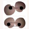
This illustration surprised me :
| Michael Gilligan | 05/03/2017 19:02:56 |
 23121 forum posts 1360 photos | As a spin-off from this recent thread **LINK** http://www.model-engineer.co.uk/forums/postings.asp?th=124817 Andrew Tinsley and I have been sharing thoughts about the geometry involved in the process described in the article by 'Base Circle'. In the course of our discussion, I remembered this [rather astonishing] illustration from 'Gears for Small Mechanisms' by W. O. Davis
. It does indeed seem clear that these four different racks all generate the same tooth profile ... So ... What is it that defines the Pressure Angle of the resulting Gear ? [ I had always assumed it to be the Pressure Angle of the generating Rack ] . Explanations, in writing or pictures, would be greatly appreciated. ... I'm feeling rather dim. MichaelG. |
| Neil Wyatt | 05/03/2017 19:31:54 |
 19226 forum posts 749 photos 86 articles | Explanation: A quick inspection of the left had 0-degree rack shows the answer, the teeth are half the width of the spaces. Rotate the gear to where those edges would be if the teeth and spaces were normal width, and the angle you turn the blank will be the pressure angle. Another explanation would be to imagine cutting a gear using a slitting saw. You can either angle the saw at the pressure angle, or move the saw sideways until the blank is rotated by the pressure angle. A third explanation: It doesn't matter what the angle is, as long as the cutting edges are tangential to the teeth at the point of contact when the rack is centred over a tooth. It follows that the pressure angle is the angle of the symmetrical rack* whose cutting edges are tangential to the teeth at the point of contact when the rack is centred over a tooth. Neil *Ignoring any addendum added to generate the dedendum. |
| Michael Gilligan | 05/03/2017 20:41:57 |
23121 forum posts 1360 photos | You may be right, Neil ... but I'm sorry to say that your explanations haven't quite sunk-in. The 0° rack is, I agree, distinctly asymmetric; but the 20° and 14.5° racks appear to be standard profiles ... so how to they each generate the same tooth-profile, and how to we decide what Pressure Angle that represents on the resulting Gear? [no quantum physics answers, please]. I think it must be to do with the different Pitch Circle diameters ... but I still can't get my head around it. MichaelG. |
| Neil Wyatt | 05/03/2017 21:18:11 |
19226 forum posts 749 photos 86 articles | I think there are truths in both our observations. Note that for the 0-degree rack the base circle and the PCD are the same. None of the illustrated generated gears have thr PCD half way up the tooth as you would expect for a 'standard' gear. In other words they are ALL examples of gears cut for an increased centre distance. This is normal practice when cutting gears with low tooth counts, you increase the separation to reduce undercutting. It's well known that involute gears are tolerant of errors in PCD and spacing. The diagram shows why - you can adjust the tooth profile bay varying the cutter infeed. It also suggests that, when making my jovilabe gears on 'incorrect' PCDs, I could have improved the tooth profiles by using extra or reduced feed - something i discovered 'by accident' without realising what was happening. Some of my gears had too-thin teeth (I should have reduced infeed) and some chunky gears were improved by a second pass with a little more infeed. I may be misreading the diagram, but it appears to suggest that if you want well-formed oversize gears then reduce the infeed or, ideally, use an over-length cutter. My 'rack formed' gears will all mate with a rack, and each-other for the same infeed but varying PCDs. What I hadn't realised is that well-formed and 'pretty' looking gears of varying PCD can be cut with the rack form. There is obviously a limit, however, otherwise you would be able to use a rack of any pressure angle to cut a rack with a different pressure angle. So where is the limit? My guess is that the straight-sided rack gives us a clue, it's ends are bevelled to provide clearance - does the principle fail when the required PCD becomes equal to or less than the diameter of the base circle? Increasing the angle, perhaps the fail point is when the PCD equals or exceeds the OD? I'm sure Andrew J. will be long in a while to explain it all for us Neil |
| Michael Gilligan | 05/03/2017 22:11:55 |
23121 forum posts 1360 photos | We live in hope ... Meanwhile; thiis is the text that follows on from Fig. 1.8.
... I hope that still falls within the bounds of 'reasonable quotation' from the book. MichaelG. |
| John Haine | 05/03/2017 22:21:48 |
| 5563 forum posts 322 photos | There's is only one involute curve from a given circle. I think this is the key. |
| Michael Gilligan | 05/03/2017 22:47:15 |
23121 forum posts 1360 photos | Posted by John Haine on 05/03/2017 22:21:48: There's is only one involute curve from a given circle. I think this is the key. . Nice thought, John ... but my problem is that in practice, gears made with various Pressure Angles have a range of obviously different tooth shapes. Post #21 in this thread includes a nice animation: https://www.chiefdelphi.com/forums/showthread.php?t=129632&page=2 Comparing those tooth shapes with the figure that I posted just doesn't seem to make sense. MichaelG. . Edited By Michael Gilligan on 05/03/2017 22:48:37 |
| Andy Ash | 05/03/2017 23:19:40 |
| 159 forum posts 36 photos | I think they get away with it in the drawing because they only define the pressure angle for a pinion against a rack. The rack has an infinite pitch circle so its involute tends to a straight line. Perhaps the consequence, is that the pinion does not have to define a specific pressure angle. I'm guessing that you could use any number of involutes for different pressure angles on the pinion, and control the actual pressure angle simply by the tooth profile on the rack. This might be the same as meshing a 15deg and a 20deg gear pair. The actual pressure angle is a different number again, but whatever it is, that is the pressure angle. I suspect that that if you did this with two gears, then you would get a pressure angle that varies as the teeth pass each other. With the rack (infinite pitch circle), the pressure angle is constant as the pinion rotates. I suspect it's like this because one of the involutes is a straight line. Even if I'm wrong, I would suggest that it's not a very helpful drawing, especially if you know anything basic about practical implementation of straight cut gears. |
| Michael Gilligan | 05/03/2017 23:45:35 |
23121 forum posts 1360 photos | Posted by Andy Ash on 05/03/2017 23:19:40:
I think they get away with it in the drawing because they only define the pressure angle for a pinion against a rack. [...] I would suggest that it's not a very helpful drawing, especially if you know anything basic about practical implementation of straight cut gears. . You may have a point, Andy ... The trouble is, I have always assumed it to be an authoritative book, The author has a good CV, and was awarded MBE in 1965 [*] It's difficult reading in places, but I had never doubted that he was right ... only doubted my ability to comprehend. MichaelG. . [*]
|
| John Stevenson | 06/03/2017 01:06:03 |
 5068 forum posts 3 photos | Posted by Michael Gilligan on 05/03/2017 23:45:35:
.
The author has a good CV, and was awarded MBE in 1965 [*]
MichaelG. Means nothing, I have an MBE as well
Motor Bike Engineer |
| jacques maurel | 06/03/2017 07:35:02 |
 84 forum posts 20 photos | What is fondamental for involute gears is the « base circle » . Visit my website: **LINK** |
| Neil Wyatt | 06/03/2017 07:53:09 |
19226 forum posts 749 photos 86 articles | OK, Imagine starting with the straight sided rack, now move to VERY long thin teeth, like 5-degrees. Imagine the teeth getting bigger and bigoer angles, until at about 80 degrees they only cut tht tips of the gears. The tip of the cutter formed from the rack gets narrower and narrower until it becomes a point, and beyond this it can't cut the full depth of the gear. Equally the upper part of the rack teeth gets wider and wider. Measuring the diagram shows that the tips become proportionally narrower as the pressure angle increases. So the angle of the rack matters not as long as it can cut the full depth, it just needs to be positioned closer to the gear centre as the PA increases and the tip adjusted if it might cause undercutting. Remember the PA of the gear is the angle the tangent to the gear makes on the PCD and the generating rack of the same PA is the ONLY one that will be tangential on the PCD when exactly aligned over a tooth. Larger PAs will be tangential outside the PCD, smaller pressure angles below the PCD. The trivial proof of this is that a form cutter in the shape of a 'negative tooth', which blends racks of multiple pressure angles each at a different depth could cut a tooth-space at one pass. It just happens to be easier to make cutters that fit tooth-spaces rather than around teeth! Next lesson - to avoid undercutting, use a rack form cutter with a larger pressure angle but make the teeth over-long so they are narrower than normal and use the usual infeed.
Neil Wyatt MBE (More Bullcrap Exposited) P.S. John I'm sitting in a typist's chair not an armchair |
| Michael Gilligan | 06/03/2017 08:11:55 |
23121 forum posts 1360 photos | Posted by jacques maurel on 06/03/2017 07:35:02:
What is fondamental for involute gears is the « base circle » . Visit my website: **LINK** . Many thanks for joining the discussion I will re-visit your videos MichaelG. |
| Michael Gilligan | 06/03/2017 08:40:17 |
23121 forum posts 1360 photos | Posted by Neil Wyatt on 06/03/2017 07:53:09:
OK, [...] Measuring the diagram shows that the tips become proportionally narrower as the pressure angle increases. So the angle of the rack matters not as long as it can cut the full depth, it just needs to be positioned closer to the gear centre as the PA increases and the tip adjusted if it might cause undercutting. [...] Next lesson - to avoid undercutting, use a rack form cutter with a larger pressure angle but make the teeth over-long so they are narrower than normal and use the usual infeed. . Neil, Perhaps the problem is that I'm trying to understand the W. O. Davis diagram in the context of the article by 'Base Circle' ... in which he illustates a typical cutter, and states: Using the suggested method, the cutter is a straightforward shaper tool, ground to the form of a rack tooth of the diametral pitch to be cut. The sides are straight and inclined to the centre-line at the same angle as the pressure angle of the tooth—i.e., usually 141/2deg. (an included angle of 29 deg.). There is no difficulty in making such a tool, and if the same tool is used for the two wheels which are to mesh together, there is not even any need for meticulous accuracy in the tool. The cutting edges are backed off in the usual way. A drawing of such a tool appears in Fig. 2. This cutter will be suitable for all numbers of teeth of this particular diametral pitch. http://neme-s.org/Shaper%20Books/Michael_Moore/shaper%20gear%20cut.pdf . In the specific case of generating a gear, by shaper, from a rack-form cutter ...I am struggling to correlate what I see as conflicting statements from the two Authors.. MichaelG. |
| Neil Wyatt | 06/03/2017 09:02:00 |
19226 forum posts 749 photos 86 articles | > there is not even any need for meticulous accuracy in the tool. The cutting edges are backed off in the usual way. There's a clue, you can correct for any error in the angle by adjusting the infeed. Also, to use a rack form cutter for a different pressure angle, you have to modify it by making it longer or reducing the tip. Neil |
| Neil Wyatt | 06/03/2017 09:26:54 |
19226 forum posts 749 photos 86 articles | Posted by jacques maurel on 06/03/2017 07:35:02:
Always interested in your contributions, Jacques! Neil |
| Neil Wyatt | 06/03/2017 09:37:16 |
19226 forum posts 749 photos 86 articles | This one of Jacque's videos is instructive. First the varies the addendum & dedendum, then the pressure angle. In the diagram above, both are changed at the same time to keep the same tooth form: Edited By Neil Wyatt on 06/03/2017 09:37:32 |
| duncan webster | 06/03/2017 15:34:20 |
| 5307 forum posts 83 photos | I always thought the guys who did the sums for gear cutting were the mega brains of the workshop. After that the mathematics of the big bang must be quite simple. I once briefly understood how double herringbone gears were cut, but only for a few moments! Edited By duncan webster on 06/03/2017 15:36:06 |


Please login to post a reply.
Magazine Locator
Want the latest issue of Model Engineer or Model Engineers' Workshop? Use our magazine locator links to find your nearest stockist!
Sign up to our Newsletter
Sign up to our newsletter and get a free digital issue.
You can unsubscribe at anytime. View our privacy policy at www.mortons.co.uk/privacy
Latest Forum Posts
- hemingway ball turner
04/07/2025 14:40:26 - *Oct 2023: FORUM MIGRATION TIMELINE*
05/10/2023 07:57:11 - Making ER11 collet chuck
05/10/2023 07:56:24 - What did you do today? 2023
05/10/2023 07:25:01 - Orrery
05/10/2023 06:00:41 - Wera hand-tools
05/10/2023 05:47:07 - New member
05/10/2023 04:40:11 - Problems with external pot on at1 vfd
05/10/2023 00:06:32 - Drain plug
04/10/2023 23:36:17 - digi phase converter for 10 machines.....
04/10/2023 23:13:48 - More Latest Posts...
- View All Topics
Support Our Partners


Shopping Partners
Subscription Offer

Latest "For Sale" Ads
- Reeves** - Rebuilt Royal Scot by Martin Evans
by John Broughton
£300.00 - BRITANNIA 5" GAUGE James Perrier
by Jon Seabright 1
£2,500.00 - Drill Grinder - for restoration
by Nigel Graham 2
£0.00 - WARCO WM18 MILLING MACHINE
by Alex Chudley
£1,200.00 - MYFORD SUPER 7 LATHE
by Alex Chudley
£2,000.00 - More "For Sale" Ads...
Latest "Wanted" Ads
- D1-3 backplate
by Michael Horley
Price Not Specified - fixed steady for a Colchester bantam mark1 800
by George Jervis
Price Not Specified - lbsc pansy
by JACK SIDEBOTHAM
Price Not Specified - Pratt Burnerd multifit chuck key.
by Tim Riome
Price Not Specified - BANDSAW BLADE WELDER
by HUGH
Price Not Specified - More "Wanted" Ads...
Get In Touch!
Do you want to contact the Model Engineer and Model Engineers' Workshop team?
You can contact us by phone, mail or email about the magazines including becoming a contributor, submitting reader's letters or making queries about articles. You can also get in touch about this website, advertising or other general issues.
Click THIS LINK for full contact details.
For subscription issues please see THIS LINK.
Digital Back Issues


Donate

 Register
 Log-in
Model Engineer Magazine
- Percival Marshall
- M.E. History
- LittleLEC
- M.E. Clock

ME Workshop
- An Adcock
- & Shipley
- Horizontal
- Mill

Subscribe Now
- Great savings
- Delivered to your door

Pre-order your copy!
- Delivered to your doorstep!
- Free UK delivery!
All Forum Topics > Manual machine tools > Involute Gear : Pressure Angle