
New Holbrook Lathe to replace my Boxford
| Joe Wardle | 15/02/2017 16:19:37 |
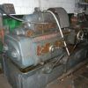
| 5 forum posts 6 photos | Hi Everyone, Just thought I would share a pic of my new Holbrook C13 Lathe that i have bought to replace my Boxford AUD.
I am keeping this on 3ph powered by rotary converter, unlike the boxford which I converted to VFD. I am in the process of cleaning up the Holbrook, I have drained all the oils and cleaned the sumps. fitted a new filter and oil hose and filled up with new oil. I need to refit the the indicator bulb lens covers. I will give everything a freshen up and tidy the paint work also. The lathe was originally sold to the Post Office Engineering Research facility at Dollis Hill, this is where the worlds first programmable computer Colossus was made. This model has plain bearings and from initial measurement on the spindle I have under 1/2 thou run out 0.00039" Obviously this should be better, but apparently the bearing adjustment is not the best nor easiest to do, lots of trial and error. any other members use holbrooks Cheers, Joe
|
| Bikepete | 15/02/2017 22:13:27 |
| 250 forum posts 34 photos | Hi Joe, not a fellow owner but just to say welcome to the forum and congratulations - that is a lathe and a half! Thanks for sharing the pic... Cheers, Pete |
| Nick_G | 15/02/2017 22:22:59 |
 1808 forum posts 744 photos | Posted by Joe Wardle on 15/02/2017 16:19:37:
I have under 1/2 thou run out 0.00039" Obviously this should be better, Cheers, Joe
. You are right. .............. Shocking, terrible, awful, horrendous.!!!! That is if you are in the production of rocket guidance systems. .......... For most model engineers who are being realistic it would be a very good number. Nick |
| thaiguzzi | 16/02/2017 02:20:07 |
 704 forum posts 131 photos | Nice lathe. Yeah, i'd swap a Boxford for that. Another PO Research Institute lathe surfaces... |
| MalcB | 16/02/2017 07:02:41 |
| 257 forum posts 35 photos | Posted by thaiguzzi on 16/02/2017 02:20:07:
Nice lathe. Yeah, i'd swap a Boxford for that. Another PO Research Institute lathe surfaces... Hi Joe and welcome. Yes this is quite uncanny that another lathe from this establishment should surface. Looking at the spindle limits that you are chasing is taking you into higher end toolroom standards which is where quite a few of these Holbrooks ended up. Not massive swing capabilities given the size and bulk of the machines, but within their limits were very precise and accurate in what they could consistantly produce. Toolrooms of this era tended to use similar sized machines for the more detailed work and some of the larger DSG's for bigger capacity requirements. It does go some way to confirming that the PO research facility did in fact have a decent budget for their equipment. Dont know the actual figures are for the weight but at a guess its got to be 1000kgs plus. This should keep you busy for a while and will no doubt end up a real satisfying piece of kit for you. Such a lot of lathe to digest. Edited By MalcB on 16/02/2017 07:03:19 |
| Joe Wardle | 16/02/2017 08:01:01 |
| 5 forum posts 6 photos | Posted by MalcB on 16/02/2017 07:02:41:
Posted by thaiguzzi on 16/02/2017 02:20:07:
Nice lathe. Yeah, i'd swap a Boxford for that. Another PO Research Institute lathe surfaces... Hi Joe and welcome. Yes this is quite uncanny that another lathe from this establishment should surface. Looking at the spindle limits that you are chasing is taking you into higher end toolroom standards which is where quite a few of these Holbrooks ended up. Not massive swing capabilities given the size and bulk of the machines, but within their limits were very precise and accurate in what they could consistantly produce. Toolrooms of this era tended to use similar sized machines for the more detailed work and some of the larger DSG's for bigger capacity requirements. It does go some way to confirming that the PO research facility did in fact have a decent budget for their equipment. Dont know the actual figures are for the weight but at a guess its got to be 1000kgs plus. This should keep you busy for a while and will no doubt end up a real satisfying piece of kit for you. Such a lot of lathe to digest. Edited By MalcB on 16/02/2017 07:03:19
Hi Malc, Yes it was a interesting read learning the history of the research station. I know the run out is nothing to be sniffed at for a 70/80 yr old lathe. Indeed it is quite a bulk, it actually weighs 2000kg. even cover plates on the cabinet are 3/4" thick cast. everything is very much over engineered. I got a full collet set, 2 x 3 jaw chucks, 2 x 4 jaw chucks, 2 x faceplates, fixed steady. tapping head and other tooling with it. I has a 3 speed motor coupled to a 2 speed gearbox. cheers,
Joe
|
| Joe Wardle | 16/02/2017 08:07:17 |
| 5 forum posts 6 photos | Posted by Nick_G on 15/02/2017 22:22:59:
Posted by Joe Wardle on 15/02/2017 16:19:37:
I have under 1/2 thou run out 0.00039" Obviously this should be better, Cheers, Joe
You are right. .............. Shocking, terrible, awful, horrendous.!!!! That is if you are in the production of rocket guidance systems. .......... For most model engineers who are being realistic it would be a very good number. Nick
Hi Nick,
I know its not drastic run out but I should be able to get it better, I will be using the lathe for work as well as hobby. Looking at your photos you have some nice bikes. I have a few too 1934 Red Panther, 1946 Velocette Mac Trials, 1955 DMW Trials, 1959 Panther M120. Joe
|
| Joe Wardle | 16/02/2017 08:09:08 |
| 5 forum posts 6 photos | Posted by Bikepete on 15/02/2017 22:13:27:
Hi Joe, not a fellow owner but just to say welcome to the forum and congratulations - that is a lathe and a half! Thanks for sharing the pic... Cheers, Pete Thanks for the welcome Pete,
It certainly is a lathe and a half weighing in at 2000+kg for a relatively small capacity lathe. everything is so well engineered. Look forward to using it.
Joe |
| John Chapman 5 | 21/02/2017 15:59:24 |
| 10 forum posts 6 photos | Hi Everyone I was very fortunate and was given a Holbrook C10 lathe which is a beast compaired to my Myford Super 7, it came from a local aerospace company, lathe being 3phase 420v having 220v domestic supply was a bit of a challenge. Have overcome the problems see write up below picture, the same write up is on the Holbrook web site.
I was in the same situation as some owners of Holbrook C10- I do not have a 3 phase supply or 415V available to power the motor as it is for my home workshop. Prior to my retirement, I was a maintenance technician at a nuclear power station and asked a good friend who was the chief electrical engineer what to do- his reply was “do you want an honest answer? I don’t know!” After a long discussion we decided against having the motor rewound as motor rewind companies tend to copy the original windings and do not usually have the expertise to reengineer the motors, without cost, so this was a non-starter. Another option was to obtain a rotary phase converter. However, there are two reasons not to go down this route. Firstly the cost (again) of the converter and secondly they are not very efficient as the motor has three different windings when changing speed and so there will be imbalance in the system. This problem also applied to a static converter as they are also poorly balanced, which affects the full power of the motor. We therefore decided the way forward was to replace the motor and use an electronic inverter drive. I had full confidence in this solution as the power station used electronic inverter drives in many places, being fully programmable with excellent reliability. However, this then required me to buy an inverter drive, a new motor and also an adaptor to make it fit the later. Motor First on the list was to look for a replacement - the original motor was 2hp but by choosing a 3hp motor and dropping down to the lower speed there is still plenty of torque available. After a long time spent time on the internet sourcing a 3 phase 220v 3hp 4 pole motor, eBay came up with a brand new Marelli motor and paid £40 which was a good start. Inverter Drive The next stage was to look for a AC Inverter Drive –and again after many hours spent searching on the internet and eBay, I took a trip to The Inverter Drive Supermarket Limited, which is in Chipping Campden, Gloucestershire. Once I explained my requirement, they recommended an ‘Altivar 12’ which is made by Schneider for the reasonable sum of £138. It took an entire evening to configure the drive as the manual was a translation and is not laid out in logical technical English. There were three main changes to the configuration:
By using an inverter drive, the speed of the lathe goes from the lowest to max 3000 rpm. This meant that with the motor running at max torque, the current would not exceed 10 amps (and therefore not tripping the house electrics!). Another advantage is there is a big gap between 3000rpm and 1492 rpm, but as the drive has a control on the front, any speed can be set manually. Contunied on next posting |
| John Chapman 5 | 21/02/2017 16:00:22 |
| 10 forum posts 6 photos | Adaptor In order mount the new motor, a spacer was required as the dimensions were different to the original motor. I started by purchasing a piece of aluminium 11 inches in diameter, 1” thick from Aluminium Warehouse. We then machined it and drilled the holes to fit the lathe and motor. Upon assembly with the spline adaptor on the motor, I then found a larger spacer was required between the motor and lathe and so I had to go back and purchase piece of aluminium 10 inches in diameter by 2 inches, which was machined in the same way. This was complemented by a piece of bar to make a spline adaptor to fit on the motor and into the lathe. The lathe end is a six splined and but I don’t have a dividing head, the gentleman who gave me the lathe (he has an industrial workshop) machined it with an indexer on his Hass machine centre. I asked him to do it oversize so it will take up the wear in the spline socket. After the spline was cut, I then spent time bluing and filing to make it a good tight fit. The spline has an OD of 1.375 and six splines. Next the adaptor need boring out to 28mm to fit the motor shaft, my other lathe is a Myford, which is not the ideal machine for larger lumps of metal, so I again gave it to my friend with the machine shop to bore out, which he had done a little undersize. I then set up the adaptor in my Myford and spent time with an emery cloth polishing the bore. It is now a good tight fit on the motor shaft. To enable any future disassembly, whilst it was in the lathe, I drilled a hole in the splined end and then taped it so if the spline needs to come off the motor shaft, it can be jacked off. A keyway slot was then cut into it to finish the job. As it is internal and a blind hole asked around if anyone had access to a slotter, albeit with no joy. In the end, I used an old fashioned method by machining a piece of bar the same diameter as the hole in the adaptor and then pressing it in and facing the end off. Where the bar joined the adaptor drilled an 8mm hole which is the width of the key. The bar was removed from the adaptor by screwing a setscrew in the hole that was taped in the end; this revealed a semi-circular slot for the keyway. A hole was drilled in the end of the keyway slot, so when cutting the keyway the swarf would not jam up the cutter. I ground up a piece of 8mm tool steel to use as a cutter, which then placed in the tool holder on the lathe. This then went in and out using the carriage taking a one thou cut till the keyway was complete. By having a semi-circular hole it made cutting a slot lot easier. Assembly The parts were all bolted together, ready for fitting. The removal of the old motor proved very difficult as the opening at the front or the back it is not large enough to pass the motor through. I had to take the motor apart to get it out. Fitting the new motor was not an easy job but there was just enough room. After a struggle and final connection however, it is in and running. The project has taken a long time, but it has been well worth the effort. I have uploaded pictures of motor and inverter drive in the hope this helps members in the same quandary that I was in. The next thing on the list is to sort out the backlash on the cross slide, as the thread is 9/16 LH Acme and is a bit of an odd size. It would be good to hear from other members on the forum what they have done |
| Neil Wyatt | 21/02/2017 16:33:43 |
 19226 forum posts 749 photos 86 articles | Posted by Joe Wardle on 16/02/2017 08:01:01:
Hi Malc, Yes it was a interesting read learning the history of the research station. I know the run out is nothing to be sniffed at for a 70/80 yr old lathe.
The Schlesinger test for spindle concentricity is 0.01mm or 0.0004" - which applies to both finish turning and toolroom lathes. It just scrapes in under the wire, so I wouldn't complain too loudly! Neil |
| Nick Kempley 1 | 17/05/2018 21:17:01 |
 10 forum posts | An old post, but for future reference the motor on a C10 comes out through the end of the machine, complete with gearbox, after removing all the electrical installation. Even then it's tight and I can't recall if some of the operating shafts have to be removed as well. When replacing it is very easy to get the speed change switch linkage upside down, whereupon the switch won't work correctly! Check the operation before switching on....
Nick |
| joly sebastien | 17/11/2021 12:49:32 |
| 1 forum posts | Hello john , i would like to do the same on my c 10 as your solution solve a lot of problems , Do you have more info as wirerig diagram ? |
| peter smith 5 | 17/11/2021 18:47:27 |
| 93 forum posts | In 1966 I had great pleasure in being given a guided tour, just me, around their factory in Harlow, Essex. WOW. I even met senior members of the family. I believe the grandson tried to resurrect the company but could not compete with cheaper imports. I watched them being hand scraped to get perfect fits, machining parts on their own lathes all being done by time served gentlemen in white coats. They really were the Rolls Royces of machine. I watched fascinated at a lathe Turning 3D elliptical press tools to press out stainless dishes. Alas all the photographs and specs that I had got destroyed in a school fire. |
| Mike Connoir | 12/01/2022 11:57:54 |
| 1 forum posts | Hi guys, I have a Holbrook H20 that I have to move from my dads place as he is now in care and I have the task of clearing out his workshop and yard. The machine was origanly in the toolroom of the long bridge car factory, dad has had it for about 20 years. It runs well and is in reasonable condition it has 3 chucks and a fixed steady with it. has any body any adea what its worth. I am thinking about replacing my Colchester master with it but not yet decided as space is of a premium, I haver not been able to find any for sale to give me an idea of value.
Any comments and advice would be appreciated Mike C |
| Roger Williams 2 | 12/01/2022 13:58:52 |
| 368 forum posts 7 photos | Holbrook H20, beautiful lathe !. Keep it somewhere !. |
| Bazyle | 12/01/2022 17:56:12 |
 6956 forum posts 229 photos | One point to consider. Does the Master do approximate metric threads without changing any wheels as some do? Probably that is more use to an amateur though there are other Holbrook features that might be good to have. |
| John Beke | 29/11/2022 21:54:58 |
| 1 forum posts | Posted by John Chapman 5 on 21/02/2017 15:59:24:
Hi Everyone I was very fortunate and was given a Holbrook C10 lathe which is a beast compaired to my Myford Super 7, it came from a local aerospace company, lathe being 3phase 420v having 220v domestic supply was a bit of a challenge. Have overcome the problems see write up below picture, the same write up is on the Holbrook web site.
I was in the same situation as some owners of Holbrook C10- I do not have a 3 phase supply or 415V available to power the motor as it is for my home workshop. Prior to my retirement, I was a maintenance technician at a nuclear power station and asked a good friend who was the chief electrical engineer what to do- his reply was “do you want an honest answer? I don’t know!” After a long discussion we decided against having the motor rewound as motor rewind companies tend to copy the original windings and do not usually have the expertise to reengineer the motors, without cost, so this was a non-starter. Another option was to obtain a rotary phase converter. However, there are two reasons not to go down this route. Firstly the cost (again) of the converter and secondly they are not very efficient as the motor has three different windings when changing speed and so there will be imbalance in the system. This problem also applied to a static converter as they are also poorly balanced, which affects the full power of the motor. We therefore decided the way forward was to replace the motor and use an electronic inverter drive. I had full confidence in this solution as the power station used electronic inverter drives in many places, being fully programmable with excellent reliability. However, this then required me to buy an inverter drive, a new motor and also an adaptor to make it fit the later. Motor First on the list was to look for a replacement - the original motor was 2hp but by choosing a 3hp motor and dropping down to the lower speed there is still plenty of torque available. After a long time spent time on the internet sourcing a 3 phase 220v 3hp 4 pole motor, eBay came up with a brand new Marelli motor and paid £40 which was a good start. Inverter Drive The next stage was to look for a AC Inverter Drive –and again after many hours spent searching on the internet and eBay, I took a trip to The Inverter Drive Supermarket Limited, which is in Chipping Campden, Gloucestershire. Once I explained my requirement, they recommended an ‘Altivar 12’ which is made by Schneider for the reasonable sum of £138. It took an entire evening to configure the drive as the manual was a translation and is not laid out in logical technical English. There were three main changes to the configuration:
By using an inverter drive, the speed of the lathe goes from the lowest to max 3000 rpm. This meant that with the motor running at max torque, the current would not exceed 10 amps (and therefore not tripping the house electrics!). Another advantage is there is a big gap between 3000rpm and 1492 rpm, but as the drive has a control on the front, any speed can be set manually. Contunied on next posting Could you tell me what the RPM of the motor is?
|
| Bezzer | 30/11/2022 16:14:17 |
| 203 forum posts 16 photos | Posted by John Beke on 29/11/2022 21:54:58:
Could you tell me what the RPM of the motor is?
Possibly not, the post is nearly 5 years old and he hasn't posted for 2 1/2 years. Edited By Bezzer on 30/11/2022 16:15:12 |
| SillyOldDuffer | 30/11/2022 16:34:02 |
| 10668 forum posts 2415 photos | Posted by John Beke on 29/11/2022 21:54:58:
Posted by John Chapman 5 on 21/02/2017 15:59:24: ...After a long time spent time on the internet sourcing a 3 phase 220v 3hp 4 pole motor, eBay came up with a brand new Marelli motor... ... The next stage was to look for a AC Inverter Drive –and again after many hours spent searching on the internet and eBay, I took a trip to The Inverter Drive Supermarket Limited, which is in Chipping Campden, Gloucestershire. ... Could you tell me what the RPM of the motor is?
Clues in John's post make an educated guess possible. On 3-phase synchronous motors: RPM = (2 / poles) * Hz * 60 So in the UK where our electricity wobbles at a dignified 50Hz, a 4-pole motor would spin at 1500 rpm. The same motor would spin at 1800 rpm in the US, because their mad-dog electrical system runs at a terrifying 60Hz. Goodness knows where it end, badly no doubt! Dave |


Please login to post a reply.
Want the latest issue of Model Engineer or Model Engineers' Workshop? Use our magazine locator links to find your nearest stockist!
Sign up to our newsletter and get a free digital issue.
You can unsubscribe at anytime. View our privacy policy at www.mortons.co.uk/privacy
- hemingway ball turner
04/07/2025 14:40:26 - *Oct 2023: FORUM MIGRATION TIMELINE*
05/10/2023 07:57:11 - Making ER11 collet chuck
05/10/2023 07:56:24 - What did you do today? 2023
05/10/2023 07:25:01 - Orrery
05/10/2023 06:00:41 - Wera hand-tools
05/10/2023 05:47:07 - New member
05/10/2023 04:40:11 - Problems with external pot on at1 vfd
05/10/2023 00:06:32 - Drain plug
04/10/2023 23:36:17 - digi phase converter for 10 machines.....
04/10/2023 23:13:48 - More Latest Posts...
- View All Topics


- Reeves** - Rebuilt Royal Scot by Martin Evans
by John Broughton
£300.00 - BRITANNIA 5" GAUGE James Perrier
by Jon Seabright 1
£2,500.00 - Drill Grinder - for restoration
by Nigel Graham 2
£0.00 - WARCO WM18 MILLING MACHINE
by Alex Chudley
£1,200.00 - MYFORD SUPER 7 LATHE
by Alex Chudley
£2,000.00 - More "For Sale" Ads...
- D1-3 backplate
by Michael Horley
Price Not Specified - fixed steady for a Colchester bantam mark1 800
by George Jervis
Price Not Specified - lbsc pansy
by JACK SIDEBOTHAM
Price Not Specified - Pratt Burnerd multifit chuck key.
by Tim Riome
Price Not Specified - BANDSAW BLADE WELDER
by HUGH
Price Not Specified - More "Wanted" Ads...
Do you want to contact the Model Engineer and Model Engineers' Workshop team?
You can contact us by phone, mail or email about the magazines including becoming a contributor, submitting reader's letters or making queries about articles. You can also get in touch about this website, advertising or other general issues.
Click THIS LINK for full contact details.
For subscription issues please see THIS LINK.


 Register
 Log-in
Model Engineer Magazine
- Percival Marshall
- M.E. History
- LittleLEC
- M.E. Clock

ME Workshop
- An Adcock
- & Shipley
- Horizontal
- Mill

Subscribe Now
- Great savings
- Delivered to your door

Pre-order your copy!
- Delivered to your doorstep!
- Free UK delivery!