Forum sponsored by:

John Wilding 8 day Weight Driven Wall Clock
Help
| Alan Charleston | 29/12/2016 07:08:18 |
| 157 forum posts 26 photos | Hi, Has anyone built the John Wilding weight driven 8 day wall clock? I started one 10-15years ago and struck a problem so I set it aside to think about it. I'm getting old and if I don't get stuck into it now, I may never complete it. I think I've resolved the problem I had initially, but I realise I'm not sure where all the bits go in relation to each other as there are no GA drawings in the book and the photos aren't much help either. I'm particularly interested in pictures looking down into the clock showing the escapement and pendulum supports. Regards, Alan C. |
| Stephen Benson | 29/12/2016 11:56:12 |
 203 forum posts 69 photos | It is a great first clock very robust design easy to make and keeps time to better than 20 seconds a week these are just photos I took when I was building it I can take more of the finished clock if need be. Mine would not run until I had opened out the pivot holes a bit which galled the engineer in me but if a clock does not rattle it will not run. It was my first clock and I made it many years ago so be kind it is still running perfectly
Edited By Stephen Benson on 29/12/2016 11:59:09 Edited By Stephen Benson on 29/12/2016 12:01:31 |
| roy entwistle | 29/12/2016 14:53:24 |
| 1716 forum posts | If you can get a look at a long case, it,s pretty much the same Roy |
| Jim C | 29/12/2016 16:59:16 |
 76 forum posts 4 photos | Hi Alan and Stephen. Thanks for asking that question and for providing the photos. I too am well into the build of same clock. I was also somewhat confused regarding the assembly of the parts. Would I be right in thinking that the 3/32 inch arbors are reduced on the ends to fit into smaller holes in the two brass plates?? Any more advice would be gratefully received. Again thanks for the input. Jim. |
| Bob Stevenson | 29/12/2016 17:21:31 |
| 579 forum posts 7 photos | Yes, the arbors are turned down at the ends to form the 'pivots'...ie parallel, highly polished bearing sections that ride in the broached bores in the plates. they should be hardened in a blow lamp flame to bright red and then tempered back carefully (I like to go just past 'straw' Edited By Bob Stevenson on 29/12/2016 17:22:12 |
| Dick H | 29/12/2016 20:26:43 |
| 141 forum posts 1 photos | Hi, I´m also building this clock. I have yet to summon the courage to pour the lead for the pendulum but the clock is ticking away in the cellar with a temporary light pendulum. There are two "cookbook"s by John Wilding for building this clock .They differ in a few details associated with the mounting of the reverse wheel etc. and the newer book (a spiral bound type assembly of the original magazine articles) adds variations on where to place the barrel so a chime and date work can be added later. This can be confusing. To get the clock running a little application of light clock oil worked wonders. As to polishing the pivots, don´t look too closely!
|
| Alan Charleston | 30/12/2016 05:44:32 |
| 157 forum posts 26 photos | Thanks Steven. That's just what I was after. I'm not sure how far I'll get. I faffed about for a week getting ready to start drilling the pivot holes in the plates, and then made a mistake on the very first one! I drilled the centre wheel pivot hole 3/32" instead of 1/16". I think I'll leave it and add a collar to the shaft to hold it in place. If I do manage to finish it I'll maybe put together a couple of general assembley drawings and post them for others in the future. Hi Dick. Have you made the shell? If so, did you use silver solder to join the two halves? Thanks for all your comments. Regards, Alan C. |
| Alan Charleston | 30/12/2016 05:54:25 |
| 157 forum posts 26 photos | Hi again Steven, I've just noticed on your 3rd photo that the collar on the right of the centre arbor doesn't rotate in the side plate. I've reamed the hole on the front plate 0.150" for this arbor. Have I got the hole on the front plate wrong as well? Regards, Alan C. |
| Stephen Benson | 30/12/2016 06:24:18 |
203 forum posts 69 photos | Posted by Alan Charleston on 30/12/2016 05:54:25:
Hi again Steven, I've just noticed on your 3rd photo that the collar on the right of the centre arbor doesn't rotate in the side plate. I've reamed the hole on the front plate 0.150" for this arbor. Have I got the hole on the front plate wrong as well? Regards, Alan C. Hi Alan No your are right it looks like the book is confusing as that is a mistake I remember making, the collar should be steel and the curved spring sits against it to allow you to turn the hands without turning the wheels to correct the time. I will take some more photo's of the finished clock today. Edited By Stephen Benson on 30/12/2016 06:25:33 |
| Stephen Benson | 30/12/2016 07:17:35 |
203 forum posts 69 photos | Right here is the finished clock after it has run continually for 8 or more years note the steel pendulum could not be bothered pouring lead. I had loads of other projects so never really finished it as I always intended to upgrade it to the later perpetual calendar version probably with bearings.
taken today complete with cobwebs
Edited By Stephen Benson on 30/12/2016 07:22:02 Edited By Stephen Benson on 30/12/2016 07:23:22 |
| Jim C | 30/12/2016 08:14:13 |
76 forum posts 4 photos | Hi Stephen. You must be very happy with the finished clock it looks great. I only hope I can finish mine to that standard. The photos will prove invaluable when I get back to the build. Hope you're open to one or two more questions as they arise. Cheers Jim.
|
| Stephen Benson | 30/12/2016 09:20:34 |
203 forum posts 69 photos | Posted by Jim C on 30/12/2016 08:14:13:
Hi Stephen. You must be very happy with the finished clock it looks great. I only hope I can finish mine to that standard. The photos will prove invaluable when I get back to the build. Hope you're open to one or two more questions as they arise. Cheers Jim.
No problems with answering questions when your clock fails to run properly after a long build it can very frustrating however the solution is often very simple because clocks of this type are quite tolerant of errors.
|
| Alan Charleston | 31/12/2016 03:11:34 |
| 157 forum posts 26 photos | Thanks Stephen. |
| Alan Charleston | 02/01/2017 06:11:07 |
| 157 forum posts 26 photos | Hi Stephen, I'm at the stage where I'm starting to look at the pendulum and escapement and I have a number of questions. 1) Is the arbor which supports the pallets and crutch 3/16" diameter with 3/32" pivots? I can't find any reference to it in the book. 2) I can't find any dimensions for siting the pivot hole or the holding screw holes in the back cock which supports the arbor. Are these not critical? 3) I can't make head or tail of the crutch. Do you have any photos of your one? Is the angled bit at the bottom of the crutch separate from the shaft and if so how is it joined. What are the two 10BA holes for? How does the top of the shaft connect to the collet? A lot of questions I know. Wilding's book is driving me crazy with the lack of dimensions on the drawings and the poor explanations on how to proceed. This is supposed to be a hobby - i.e. fun! Not much of that at the moment. Regards, Alan C. |
| Dick H | 02/01/2017 11:46:55 |
| 141 forum posts 1 photos | Hi Alan, I assume you are working from the older book for building the clock. I started with this and then switched to the newer version. Just looking at the old (red dust-cover) book the information you seek is scattered all over the place. 1) the arbor which supports the pallets and crutch is 3/32" (~2.4 mm), this matches the hole drilled when making the pallets (p.37, left hand column line 13).The escape and pallet pivots are 0.050" in dia. (p.29, Fig 42. bottom right). The newer book uses 1/16" pivots. 2) The back cock. The older book uses a back cock made of bits of brass silver soldered together, in the newer, a brass plate is supported by two pillars. I would take the drawing a p.42 Fig 68 as being a scale diagram (approx 75%). The holes back plate are drilled and tapped to suit the position of the back cock sitting on the pivot protruding through an arbor sized hole in the back-plate, even then there will be a little bit of potential movement, so it is suggested to add locating pins as well. This is before cutting out the upside down keyhole shaped hole in the backplate to accommodate the adjustable collet. 3) The crutch can be made out of one piece of brass and bent (the newer book uses 1/16" mild steel strip) or made from two pieces and soldered together (p.44). the top of the crutch has a central hole to sit on the arbor and is then held by two small screws ( approx. M 1.6-1.8 metric) to the adjustable collet. The two 10 BA holes in the foot of the crutch are to hold small plate to narrow and adjust clearance between the crutch and the lower brass block on the suspension spring, this is difficult to see in Fig 79 on p.45, and it is also visible in Fig 2 on p.5, once you have an idea what to look for. The crutch I made is simple steel with a slot. Hope this helps. Living abroad my clock is a wild mixture of imperial and metric. The older book uses lantern pinions, the newer steel pinions. Having sat down to cross read the two, I see there are lots of differences. Hope this helps.
|
| NJH | 02/01/2017 12:46:40 |
 2314 forum posts 139 photos | I made all the bits for this clock about 20years ago - enjoyed making it and then we moved house! Modern house with lower ceiling heights and nowhere suitable to put clock so all the bits are in a workshop drawer until (maybe) we move again!! Norman |
| Alan Charleston | 02/01/2017 20:08:57 |
| 157 forum posts 26 photos | Hi Dick, Thanks for the information. It's just as well I asked for help instead of charging ahead on my own. You are right about me using the old (1990) book. I have made the lantern pinions. I'm the same as you with regard to a mixture of imperial and metric. Regards, Alan C. |
| Alan Charleston | 06/01/2017 05:33:42 |
| 157 forum posts 26 photos |
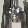
Thanks for the help. I got stuck in and have made the back cock.
The plate connecting the two pieces of angle was silver soldered and the pendulum post was soft soldered into position. I'm pretty sure it will be strong enough. I haven't slit the post for the pendulum yet as I don't have the .006" spring steel or a 0.2mm slitting saw. I can source some .006" spring steel shim plate locally. Will this be OK for the suspension spring? I will order some 0.2mm slitting saws from CTC Tools. At $2-50 each I'll get a few of them I think. The thinnest saw I've used to date is 1/16" so any suggestions about things to watch out for will be welcome. Here is a picture showing where I am at the moment. The wheels and pinions haven't been loctited to the arbors yet. I want to have the pallets in position so I can see the whole train before I set them in their final positions.
Thanks again for your help. Regards, Alan C. |
| Jim C | 06/01/2017 07:36:38 |
76 forum posts 4 photos | Hi Alan, just wondering if you have come across the website of Ian T Cobb ? He can supply clock related parts. I have no connection only a satisfied customer. looks like your clock is coming on well. I must return to mine when time allows !!!! regards, Jim. |
| Brian H | 06/01/2017 08:55:32 |
 2312 forum posts 112 photos | I can vouch for Ian Cobb having had some materials such as Invar for pendulum rods and silvering powder from him. A good source of spring steel for suspensions etc is feeler gauge material, sold as a spool or as cut pieces from model engineering suppliers. Brian |


Please login to post a reply.
Magazine Locator
Want the latest issue of Model Engineer or Model Engineers' Workshop? Use our magazine locator links to find your nearest stockist!
Sign up to our Newsletter
Sign up to our newsletter and get a free digital issue.
You can unsubscribe at anytime. View our privacy policy at www.mortons.co.uk/privacy
Latest Forum Posts
- *Oct 2023: FORUM MIGRATION TIMELINE*
05/10/2023 07:57:11 - Making ER11 collet chuck
05/10/2023 07:56:24 - What did you do today? 2023
05/10/2023 07:25:01 - Orrery
05/10/2023 06:00:41 - Wera hand-tools
05/10/2023 05:47:07 - New member
05/10/2023 04:40:11 - Problems with external pot on at1 vfd
05/10/2023 00:06:32 - Drain plug
04/10/2023 23:36:17 - digi phase converter for 10 machines.....
04/10/2023 23:13:48 - Winter Storage Of Locomotives
04/10/2023 21:02:11 - More Latest Posts...
- View All Topics
Support Our Partners


Shopping Partners
Subscription Offer

Latest "For Sale" Ads
- Reeves** - Rebuilt Royal Scot by Martin Evans
by John Broughton
£300.00 - BRITANNIA 5" GAUGE James Perrier
by Jon Seabright 1
£2,500.00 - Drill Grinder - for restoration
by Nigel Graham 2
£0.00 - WARCO WM18 MILLING MACHINE
by Alex Chudley
£1,200.00 - MYFORD SUPER 7 LATHE
by Alex Chudley
£2,000.00 - More "For Sale" Ads...
Latest "Wanted" Ads
- D1-3 backplate
by Michael Horley
Price Not Specified - fixed steady for a Colchester bantam mark1 800
by George Jervis
Price Not Specified - lbsc pansy
by JACK SIDEBOTHAM
Price Not Specified - Pratt Burnerd multifit chuck key.
by Tim Riome
Price Not Specified - BANDSAW BLADE WELDER
by HUGH
Price Not Specified - More "Wanted" Ads...
Get In Touch!
Do you want to contact the Model Engineer and Model Engineers' Workshop team?
You can contact us by phone, mail or email about the magazines including becoming a contributor, submitting reader's letters or making queries about articles. You can also get in touch about this website, advertising or other general issues.
Click THIS LINK for full contact details.
For subscription issues please see THIS LINK.
Digital Back Issues


Donate

 Register
 Log-in
Model Engineer Magazine
- Percival Marshall
- M.E. History
- LittleLEC
- M.E. Clock

ME Workshop
- An Adcock
- & Shipley
- Horizontal
- Mill

Subscribe Now
- Great savings
- Delivered to your door

Pre-order your copy!
- Delivered to your doorstep!
- Free UK delivery!
All Forum Topics > Clocks and Scientific Instruments > John Wilding 8 day Weight Driven Wall Clock