Forum sponsored by:

Omron Varispeed V7 - Help?
| Cornish Jack | 10/10/2016 16:35:32 |
| 1228 forum posts 172 photos |
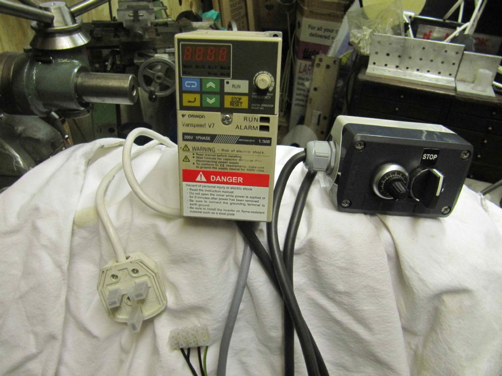
The first of the pics above shows the vfd as received - all wired up and ready to go. The second shows 'as is' now - 'helpful' recovery gang's efforts following the destruction of house and workshop in 2013. Ihave a copy of the manual but cannot find any reference to the pendant controls and/or how they are wired in. Any forum member with knowledge of this particular vfd who could offer advice, please? rgds Bill |
| Clive Foster | 10/10/2016 17:13:25 |
| 3630 forum posts 128 photos | If the manual I found for download applies to your inverter page 222 "Standard Wiring" and 224 "Terminal Descriptions" (that section actually starts on 223) have the information you need. Page 36 "Wiring the Control Circuits" shows you where the connections are. I assume you have a speed control potentiometer and a two way centre off switch for forward & reverse selection on your pendant. From the diagram on page 222:- The speed control potentiometer goes between Terminals FS and FC with the wiper going to FR The common terminal on the forward reverse switch goes to terminal SC, the forward on terminal goes to S1 and the reverse on terminal goes to S2. Stop is when the switch is in its centre (off) position. Hopefully nothing else has been tampered with. Clive |
| Cornish Jack | 10/10/2016 19:07:56 |
| 1228 forum posts 172 photos | Many Thanks, Clive. I'll see if I can sort it out from those references. I have to admit that, looking through the manual, my eyes had started to wobble long before getting to that sort of page count!! Will let you know how I get on. rgds Bill |
| Clive Foster | 10/10/2016 22:09:59 |
| 3630 forum posts 128 photos | Posted by Cornish Jack on 10/10/2016 19:07:56:
my eyes had started to wobble long before getting to that sort of page count!! Will let you know how I get on. rgds Bill Whooh yeah! Apparently its union rules for the VFD manual writers association that normal folks shall not be able to find the information they require without grave risk to their sanity and being put to sleep at least twice en route. Fortunately it also appears to be union rules that somewhere in the manual there shall be pretty pictures showing the basic connections for ordinary set-ups, the layout of the terminal blocks and a table saying what each terminal is called and indicating what it does. Unfortunately there is no rule that these shall be usefully grouped together near the front of the book where ordinary folk can find them or that the terminal function descriptions shall be understandable without needing at least a masters degree in tech speak. Guess that would be just too easy. Not quite so bad when you have some idea of what to look for as its relatively easy to speed scan until you find the pictures. I suggest that you find the download on the Omron site and print out the Standard Wiring diagram as large as you can. A4 would probably do, A3 would be better. Much easier to follow on a big picture and room to make notes such as wire colours and make (red?) circles round the important to you bits. You could just print sectional enlargements of the important parts of the picture but I find such rather harder to get on with than a more complete view. Certainly appears to be union rules that the version in the box be printed too small to be easily followed. Probably a big prize awaiting the first VFD maker to produce a wiring picture meeting the standard "in the box" level of incomprehensibility when printed to Double Elephant size. Hope it all works out. Clive. |
| Cornish Jack | 11/10/2016 14:47:27 |
| 1228 forum posts 172 photos | Thank you again, Clive. Your assessment of the 'clarity quotient' of vfd manuals/wiring diagrams is spot on! It's not helped by my lack of familiarity with such things. Apropos which, I am about to ask what may be the ultimate idiot question - in the photo below, am I correct in thinking that the 3 wires to the right are the fwd/rev connections and the 3 to the left, the speed connections. Assuming that to be so, unfortunately I have come to a halt!! While I can see on the wiring diagram (P222/3) the item 'Digital Operator Frequency Setting Potentiometer (Speed control?), the annotations for its connections (Block CN2) don't mean a thing to me. Additionally, I cannot see any indications of connections for the fwd/rev function.
I'm sure that 'for them as knows', it is all quite straightforward but it eludes me. Any further useful pointers would be much appreciated. rgds Bill |
| john fletcher 1 | 11/10/2016 16:53:33 |
| 893 forum posts | Bill, The instructions which Clive has given you are correct. You have to take the cover off the inverter front and see the rows of small terminals,( usually several |
| Cornish Jack | 11/10/2016 18:15:07 |
| 1228 forum posts 172 photos | Thank you John. That sounds like something I could manage without messing up too much! rgds Bill |
| Clive Foster | 11/10/2016 19:07:47 |
| 3630 forum posts 128 photos | Bill Sounds like you are sorted then. Might help anyone coming across this thread in future to note that the Digital Operator Frequency Setting Potentiometer is the build in control connected to he knob on the box. The pendant connection is over on the other side indicated by the Frequency Ref curly bracket. Basically Frequency is VFD maker speak for speed. Its most likely that the centre terminal of your speed control potentiometer goes to the wiper. If so the red wire will go to connector FR. Blue wire to FC and White wire to FS is probably right but if the knob turns the wrong way to speed up or slow down reverse them. May be best to start off with the potentiometer in the middle so as not to get a jump to flat out if the potentiometer connections are the wrong way round and what you think is dead slow setting is actually warp speed. The turquoise coloured (on my display anyway) wire should go to terminal SC with the black and yellow wires going to S1 and S2 as appropriate to get things turning the right way. As John says the indentification labels on the terminals are usually small and hard to read. They are often a bit offset from the terminal itself and frequently upside down if the box is mounted on the wall or a machine. Which makes it very easy to connect to the terminal next door to the one you think you are connecting to. Been there, dunnit, caught the error under the "have a coffee then go back and check system". Another place where big printout of the picture with scribble room helps as you can more easily physically count from one end to confirm where the terminal is. Clive. Edited By Clive Foster on 11/10/2016 19:08:06 |
| Cornish Jack | 12/10/2016 11:29:43 |
| 1228 forum posts 172 photos | Clive, thank you very much. I'll have a go at reconnecting later today - with fingers tightly crossed (metaphorically, of course!!). What you and John are indicating sounds fairly straightforward - with a little concentration One area which does concern me still is on the original photo of the unit , as received. There appears in the centre a 'chocolate block' with four wires connected - two in, two out. I have no recollection whatsoever of that part of the setup and cannot recall anything which might have required it. ... Fingers VERY tightly crossed!! rgds Bill |
| Cornish Jack | 12/10/2016 15:33:25 |
| 1228 forum posts 172 photos | Instant (almost) update. Using the guidance above, I removed the front panel and checked the connector block and it all looked simple enough, however ... the old connections were via crimp pin terminals and they aren't reusable. Needless to say, I have nothing similar in my 'leccie bits' box, so the order has been placed on Ebay and they should be here next Monday. 'Best laid plans ganging aft agley' again! rgds Bill |
| Cornish Jack | 25/10/2016 11:48:20 |
| 1228 forum posts 172 photos | Much belated update. First, the good news - NO magic smoke (yet!!) Next the bad news. Switch on, operate direction and speed controls (on the pendant) produce noises like motor running, accelerating and stopping but NO movement on motor output pulley! Now having coffee and biccies to restore nerves but unsure (totally foxed) as to how to proceed. Suggestions from wiggly amps experts very welcome. rgds Bill
|
| Ian Parkin | 25/10/2016 12:37:56 |
 1174 forum posts 303 photos | nothing in between Inverter And motor? Inverter wired direct? And all connections good? |
| Cornish Jack | 25/10/2016 17:22:27 |
| 1228 forum posts 172 photos | Ian - Inverter direct to motor but pendant is wired into inverter to provide Fwd/Rev and speed variation. Connections made into inverter sockets using proper sized crimp pins (took a fortnight to source the correct size!!) Will check individual wires with a digimeter. rgds Bill |
| SillyOldDuffer | 25/10/2016 20:25:15 |
| 10668 forum posts 2415 photos | Posted by Cornish Jack on 25/10/2016 17:22:27: ... Connections made into inverter sockets using proper sized crimp pins (took a fortnight to source the correct size!!) Will check individual wires with a digimeter. ... Bill I've had bad experiences with crimping. It's more difficult to get right than you might expect. Nowadays I tend to avoid using them partly because I don't have the decent tools needed to get consistent results. It's possible you have an intermittent connection due to a bad crimp. Intermittent connections are harder to detect with a digital meter than an analogue but try giving the wires a good waggle as you check continuity. Also do a close visual inspection: all the wires should be firmly clamped at the correct crimping point with no loose strands or other physical issues. Be warned though: I've produced a few good looking crimps that turned out to be poor electrically. Good luck Dave Edited By SillyOldDuffer on 25/10/2016 20:27:21 |
| Cornish Jack | 25/10/2016 21:22:29 |
| 1228 forum posts 172 photos | Thank you, Dave. The point re. crimps is well taken. It's the first time I've used this particular type and they are necessary because of the tiny fixing sockets. I intend to approach this problem with a deal of caution - the second attempt at operating blew the Garage/ workshop breaker! rgds Bill |
| Cornish Jack | 19/10/2017 14:21:59 |
| 1228 forum posts 172 photos | A thread ressurection seeking assistance again. I have again got to the point of re-installing the Myford (after 3 years of lying idle, storage, etc. Nothing significant changed since the above post. Plugged in the VFD/motor combination and switched on the power. The VFD 'lit up' and appeared to be OK. Tried the motor control forward and reverse and the motor emitted sounds as though it was running - but nothing moved!! Checked the fan, in case it was just that but both it and the output pulley were stationary. As a 'bear with very little 'electrical' brain', I am totally 'foxed'. Can anyone with VFD/motor expertise offer any checks/solutions, please? As pointed out in previous posts, replies need to be at the 'nursery school' level!! rgds Bill |
| Cornish Jack | 19/10/2017 23:41:24 |
| 1228 forum posts 172 photos | One time when a lack of response is helpful! - saves me having to apologise for being a total prat (again!) Did what I should have done before posting - checked the wiring and ...
Not just the obvious one but all three on that side of the box were badly crimped and making poor contact. The reason was also clear - the lack of any sort of strain relief. There is a great need for a forehead-slapping emoticon! rgds Bill |
| Neil Wyatt | 20/10/2017 15:05:43 |
 19226 forum posts 749 photos 86 articles | Just glad it didn't short out and cause any damage! A big zip tie around the cable just as it enters the box might help stop it being pulled again. Neil |
| Muzzer | 20/10/2017 15:39:49 |
 2904 forum posts 448 photos | If you wind a fat cable tie several times around the cable before you tighten it up hard with 2 pairs of pliers (levered against each other), it will almost never slip. Still possible to rotate but presumably that's unlikely here. Murray |
| Cornish Jack | 20/10/2017 18:15:00 |
| 1228 forum posts 172 photos | Thank you Neil and Murray - must bear the cable tie idea in mind. I, as usual, did it the more fiddly way by making a clamp strip to match one from a defunct 3 pin plug and screwed them together - seems to be OK. Happy that it's working but I would love to hear why the motor was emitting rotation noises without moving when previously tried rgds Bill |


 all marked up as Clive has said, they tiny and not easily read Fs, Fc and Fr. If there isn't wires in those position, then put three wires into those terminals Write down which colours you use.The other ends of those same coloured wire connect the speed control potentiometer get the colour RIGHT. Next locate in the inverter terminals Sc, S1 and S2 and as before connect the remaining three wires into those same three terminals. Finally connect the same three wires into the correct terminals in the forward and reverse switch. Look out for a PM. John
Please login to post a reply.
Magazine Locator
Want the latest issue of Model Engineer or Model Engineers' Workshop? Use our magazine locator links to find your nearest stockist!
Sign up to our Newsletter
Sign up to our newsletter and get a free digital issue.
You can unsubscribe at anytime. View our privacy policy at www.mortons.co.uk/privacy
Latest Forum Posts
- *Oct 2023: FORUM MIGRATION TIMELINE*
05/10/2023 07:57:11 - Making ER11 collet chuck
05/10/2023 07:56:24 - What did you do today? 2023
05/10/2023 07:25:01 - Orrery
05/10/2023 06:00:41 - Wera hand-tools
05/10/2023 05:47:07 - New member
05/10/2023 04:40:11 - Problems with external pot on at1 vfd
05/10/2023 00:06:32 - Drain plug
04/10/2023 23:36:17 - digi phase converter for 10 machines.....
04/10/2023 23:13:48 - Winter Storage Of Locomotives
04/10/2023 21:02:11 - More Latest Posts...
- View All Topics
Support Our Partners


Shopping Partners
Subscription Offer

Latest "For Sale" Ads
- Reeves** - Rebuilt Royal Scot by Martin Evans
by John Broughton
£300.00 - BRITANNIA 5" GAUGE James Perrier
by Jon Seabright 1
£2,500.00 - Drill Grinder - for restoration
by Nigel Graham 2
£0.00 - WARCO WM18 MILLING MACHINE
by Alex Chudley
£1,200.00 - MYFORD SUPER 7 LATHE
by Alex Chudley
£2,000.00 - More "For Sale" Ads...
Latest "Wanted" Ads
- D1-3 backplate
by Michael Horley
Price Not Specified - fixed steady for a Colchester bantam mark1 800
by George Jervis
Price Not Specified - lbsc pansy
by JACK SIDEBOTHAM
Price Not Specified - Pratt Burnerd multifit chuck key.
by Tim Riome
Price Not Specified - BANDSAW BLADE WELDER
by HUGH
Price Not Specified - More "Wanted" Ads...
Get In Touch!
Do you want to contact the Model Engineer and Model Engineers' Workshop team?
You can contact us by phone, mail or email about the magazines including becoming a contributor, submitting reader's letters or making queries about articles. You can also get in touch about this website, advertising or other general issues.
Click THIS LINK for full contact details.
For subscription issues please see THIS LINK.
Digital Back Issues


Donate

 Register
 Log-in
Model Engineer Magazine
- Percival Marshall
- M.E. History
- LittleLEC
- M.E. Clock

ME Workshop
- An Adcock
- & Shipley
- Horizontal
- Mill

Subscribe Now
- Great savings
- Delivered to your door

Pre-order your copy!
- Delivered to your doorstep!
- Free UK delivery!
All Forum Topics > Electronics in the Workshop > Omron Varispeed V7 - Help?