Forum sponsored by:

Pre war Colchester Master
| hth | 21/08/2015 12:25:28 |
| 93 forum posts 22 photos | hi
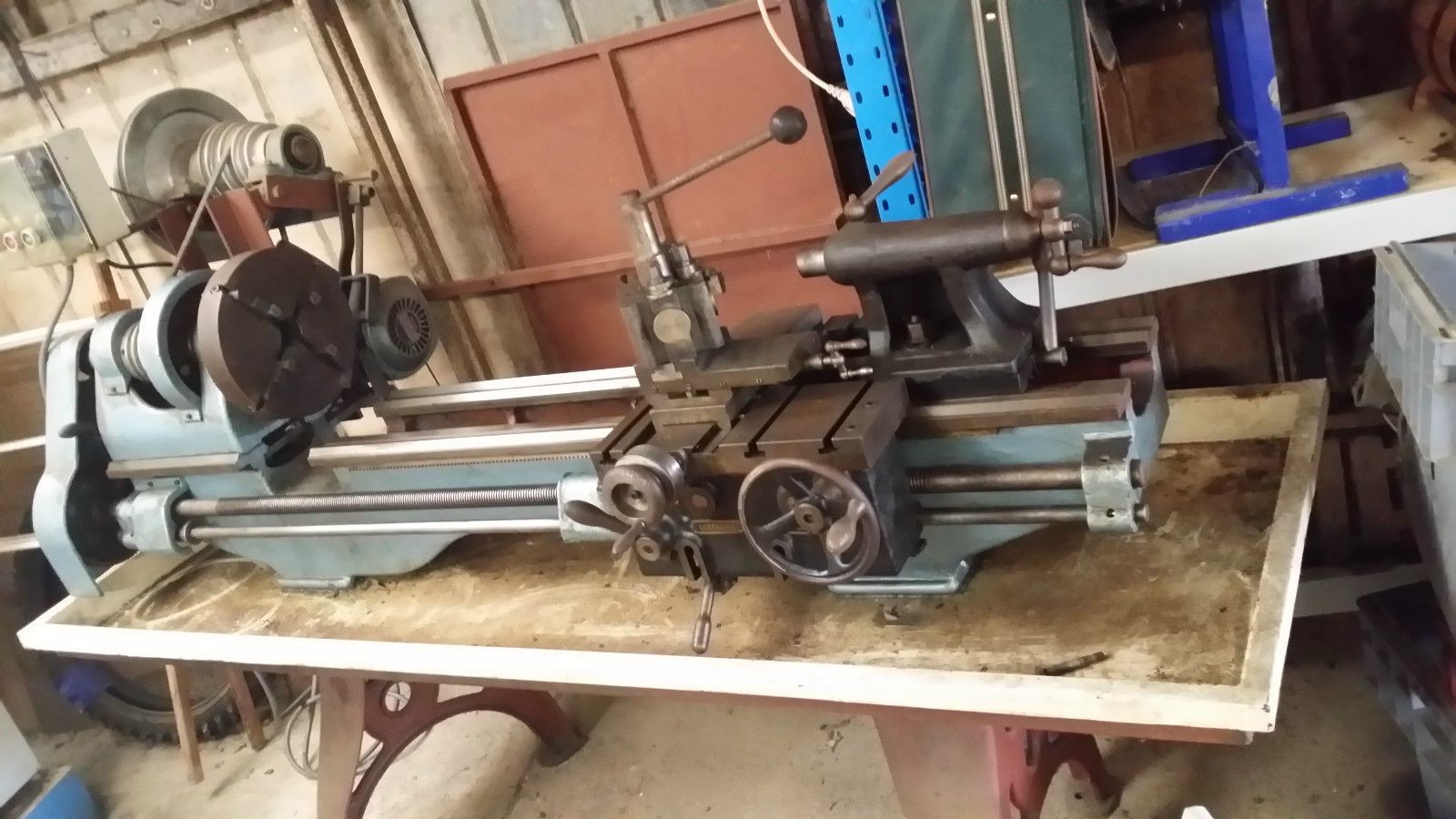
I recently found a old Colchester Master lathe, it looks pre war to me . It is in nice condition as its been looked after . A neat conversiojn to V belt drive is a handy mod. It has 24 speeds . I would like to know the gauge of the original drip tray ?
I am thinking of replacing the wick oilers on the spindle bearings with drip oilers . Mike in Australia
Edited By hth on 21/08/2015 12:29:48 Edited By hth on 21/08/2015 12:32:39 |
| Mick Henshall | 21/08/2015 12:53:17 |
 562 forum posts 34 photos | Now that looks a nice piece of kit,congratulations-24 speeds crikey I have just 6 Mick
|
| Mick Henshall | 21/08/2015 12:53:17 |
562 forum posts 34 photos | I seem to have posted reply twice, second time I done this well I am an OAP!!!
Edited By Mick Henshall on 21/08/2015 12:57:59 Edited By Mick Henshall on 21/08/2015 13:00:08 |
| hth | 21/08/2015 13:05:42 |
| 93 forum posts 22 photos | hi Mick
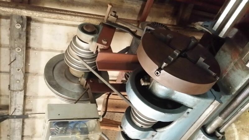
The motor and counter shaft pullies have three belt positions, the main spindle pulley cone has four belt positions . Yes it is a beaut old lathe and in great condition . |
| Neil Wyatt | 21/08/2015 13:13:55 |
 19226 forum posts 749 photos 86 articles | Looks like the 38 to 39 model see HERE Enjoy!
Neil |
| Ady1 | 21/08/2015 14:13:34 |
 6137 forum posts 893 photos | Looks like an ML7 on steroids, a real metal muncher |
| John McNamara | 21/08/2015 16:47:13 |
 1377 forum posts 133 photos | Hi Mike Gee for a minute I thought it was my old lathe! I also removed the original drip tray and replaced it with a very similar one to the one shown in your photo The original tray was far too small to be useful. I also made up a drive frame using angle and a countershaft supported by ball plumber blocks, although It was fitted with a variable speed drive. Yours does not appear to have a gap bed and the engagement lever for the back gear is not visible, or was it discarded when the v belt pulleys were fitted on the spindle? The machine as built had a flat belt step pulley. For the drive I just bored out a cast iron double v pulley to a close fit on one of the original flats and drove that. Apart from that almost the identical. Your machine almost certainly had a shiny black Japan finish. Regards Oh And the gauge of the tray? Edited By John McNamara on 21/08/2015 16:59:13 |
| frank brown | 21/08/2015 19:22:48 |
| 436 forum posts 5 photos | This is what I used on a slightly smaller lathe :- http://www.airflow-uk.co.uk/Heavy-Duty-Drip-Tray.html Just needs a drop of sealer on the corners. Frank |
| hth | 22/08/2015 01:15:46 |
| 93 forum posts 22 photos | Hi John
Thank you for the tray info .
I live in West Gippsland , near Warragul. I wonder what you did with the original drip tray ? Amazing , you had a similar model. Yes the gap bed is on mine, maybe it isn't visible in the pic. The back gear lever is there , hiding .Ok the colour black Japan .. good
I have a few other lathes , a Chipmaster and a Harrison L5 and a pre war Holbrook T13 . I am addicted to collecting these old gems ! |
| hth | 28/08/2015 02:40:11 |
| 93 forum posts 22 photos | Hi
The spindle taper in this old lathe . Would it be a MT 5 ?
Thanks mike |
| Ady1 | 28/08/2015 08:45:43 |
6137 forum posts 893 photos | Morse 3 in the tailstock of the 6.5 inch geared head version spindle bore 1-9/16" no morse mentioned.... sounds suspicious... Edited By Ady1 on 28/08/2015 09:00:46 |
| Keith Long | 28/08/2015 08:53:16 |
| 883 forum posts 11 photos | Mike - don't be too surprised if it turns out to be neither 4 or 5MT but something in between. Colchester among several other makers used what is often known as a 41/2MT taper roughly 1.5 inch dia at the larger end and 1.25 at the smaller. Bushes are available but can be expensive, but if you've gfot the facilities then turning one isn't that difficult and you can make it accept whatever you want up the middle. I've got the same issues with an IXL lathe with a Colchester Master clone headstock. I'm expecting to make several bushes (mild steel will be OK) with a range of 1-4MT centres and might make one with an R8 centre to accept the milling chuck as well. |
| John McNamara | 28/08/2015 09:05:25 |
1377 forum posts 133 photos | Hi Mike I wish I could tell you the taper on mine.... Unfortunately it came with a plug so I never had to make one. In this case I made two at a time, so the piece could be turned end for end while checking the taper fit, one Morse taper 4 and one int40 machine taper. regards |
| hth | 28/08/2015 10:05:40 |
| 93 forum posts 22 photos | Thank you for the replies everyone. Yes the tailstock is MT3 . I need to know what the 4 1/2 MT taper is in terms of thou per inch .
4MT = .05193" per inch
5MT= .05262" per inch
The machining data books I have do not list the 4 1/2 MT .
Mike Edited By hth on 28/08/2015 10:07:11 |
| Keith Long | 28/08/2015 17:12:33 |
| 883 forum posts 11 photos | Mike - here's a link ot a page that gives you the data for 41/2MT. Bearing in mind the age of your lathe, you'd be better machining the nose adaptor to fit the lathe by testing the fit with engineers blue than by trying to machine to a given taper/inch. Given how close all the morse tapers are then I don't think that trying to machine to an absolute value will achieve the fit that you'll get by the trial method - do you have the facilities to set the absolute angle to 5 places of decimals - and it's always possible that in it's life someone has "cleaned" the taper up or adjusted it anyway. |
| daveb | 28/08/2015 18:20:04 |
| 631 forum posts 14 photos | That's a big Myford! A very acceptable 'rolled edge' can be made by slitting 10 or 12mm steel tube and welding to the edge of the tray. Corners may be mitred or use a suitable (same size outside diameter as tube) elbow for a rounded corner. |
| hth | 29/08/2015 01:08:43 |
| 93 forum posts 22 photos | Ok very good
Yes I agree , the tolerances are very small ... blueing is the answer .
Rolled edge, yes good idea re the tube . I have done that trick, making wings for an old vehicle
Mike |
| hth | 13/09/2015 10:46:35 |
| 93 forum posts 22 photos | Hi
This old Colchester has a thrust bearing located on the main spindle somewhere but I cannot find it as yet . I have not dismantled anything and it is difficult to see what's in there . I think the thrust bearing is hidden inside the small gear that drives the back gear ? Any info appreciated . Mike |
| Ady1 | 13/09/2015 12:37:22 |
6137 forum posts 893 photos | If I was you I would get a proper manual, that's a high end manual machine tool you're messing with There's bound to be a yahoo type group with the experience and details you need to get going Edited By Ady1 on 13/09/2015 12:50:23 |
| John McNamara | 13/09/2015 14:29:33 |
1377 forum posts 133 photos | Hi Mike To remove any play the thrust bearing is tightened against the spindle by a large threaded ring at the left hand end of the spindle that also retained the drive train gear and a collar. you will need a pin spanner. you should find the bearing under the small cover to the left as seen in your photo. The back gear on mine was under the spindle within the headstock. It was made from cast Iron as was the bull gear. The gears were badly damaged when I got the lathe. I had to repair teeth on the large back gear and replace the small pinion altogether. I also had to make up a new bull gear from one scrounged from a dealer not easy to find. It was a big job. If yours are intact without missing teeth you are lucky. Clearly they do not like to be overloaded. You will probably find there is only a single half nut that engages the leadscrew for screw cutting this is moved down onto the leadscrew by a lever. It too is cast Iron, it is guided by a 3/4 inch (from memory) cast iron spigot. I managed to break that one day while cutting a heavy thread. The fix for that was to bore a slightly smaller hole in the nut body and Loctite in a stepped 3/4 inch mild steel pin to replace the cast iron pin... I still have the pin! saw it the other day in a box.... The gears on the back of the apron are open. there is no sealed gearbox I would dismantle the apron and clear out the detritus that has accumulated there before greasing everything and reassembling. One nice feature of the lathe is how easy it is to adjust the headstock alignment. Just loosen (firm not too loose) the 4 bolts that clamp it down (Look up under the headstock between the ways) You can then adjust the spindle axis until it is perfectly parallel to the bed via small jack screws under each end of the headstock. Regards Edited By John McNamara on 13/09/2015 14:32:10 |
 .
.Please login to post a reply.
Magazine Locator
Want the latest issue of Model Engineer or Model Engineers' Workshop? Use our magazine locator links to find your nearest stockist!
Sign up to our Newsletter
Sign up to our newsletter and get a free digital issue.
You can unsubscribe at anytime. View our privacy policy at www.mortons.co.uk/privacy
Latest Forum Posts
- *Oct 2023: FORUM MIGRATION TIMELINE*
05/10/2023 07:57:11 - Making ER11 collet chuck
05/10/2023 07:56:24 - What did you do today? 2023
05/10/2023 07:25:01 - Orrery
05/10/2023 06:00:41 - Wera hand-tools
05/10/2023 05:47:07 - New member
05/10/2023 04:40:11 - Problems with external pot on at1 vfd
05/10/2023 00:06:32 - Drain plug
04/10/2023 23:36:17 - digi phase converter for 10 machines.....
04/10/2023 23:13:48 - Winter Storage Of Locomotives
04/10/2023 21:02:11 - More Latest Posts...
- View All Topics
Support Our Partners


Shopping Partners
Subscription Offer

Latest "For Sale" Ads
- Reeves** - Rebuilt Royal Scot by Martin Evans
by John Broughton
£300.00 - BRITANNIA 5" GAUGE James Perrier
by Jon Seabright 1
£2,500.00 - Drill Grinder - for restoration
by Nigel Graham 2
£0.00 - WARCO WM18 MILLING MACHINE
by Alex Chudley
£1,200.00 - MYFORD SUPER 7 LATHE
by Alex Chudley
£2,000.00 - More "For Sale" Ads...
Latest "Wanted" Ads
- D1-3 backplate
by Michael Horley
Price Not Specified - fixed steady for a Colchester bantam mark1 800
by George Jervis
Price Not Specified - lbsc pansy
by JACK SIDEBOTHAM
Price Not Specified - Pratt Burnerd multifit chuck key.
by Tim Riome
Price Not Specified - BANDSAW BLADE WELDER
by HUGH
Price Not Specified - More "Wanted" Ads...
Get In Touch!
Do you want to contact the Model Engineer and Model Engineers' Workshop team?
You can contact us by phone, mail or email about the magazines including becoming a contributor, submitting reader's letters or making queries about articles. You can also get in touch about this website, advertising or other general issues.
Click THIS LINK for full contact details.
For subscription issues please see THIS LINK.
Digital Back Issues


Donate

 Register
 Log-in
Model Engineer Magazine
- Percival Marshall
- M.E. History
- LittleLEC
- M.E. Clock

ME Workshop
- An Adcock
- & Shipley
- Horizontal
- Mill

Subscribe Now
- Great savings
- Delivered to your door

Pre-order your copy!
- Delivered to your doorstep!
- Free UK delivery!
All Forum Topics > General Questions > Pre war Colchester Master