Forum sponsored by:

CovMac Lathes
| CHRISTOPHER MILLS 1 | 29/09/2014 17:35:17 |
 152 forum posts 61 photos | Many thanks Brian - I still have the option, though it will increase time pressure on the day, of de-concreting legs after the bed is lifted off. Presently, nuts holding plinth and legs on are all off. I could replace them. Almost certainly, the chip tray is presently a loose item sitting heavily sandwiched between bed and legs. There would not appear to be any other attachments aside of the four bolts, which I have removed. I could de-concrete headstock plinth, but leave tailstock legs in their fillet of cement until the bed is moved? That sounds a safe way of managing the tray? I agree, the tailstock legs are a bit delicate looking, and Phil said his flexed alarmingly when he was moving his CovMac. Chris.
|
| Phil Whitley | 29/09/2014 18:34:11 |
 1533 forum posts 147 photos |
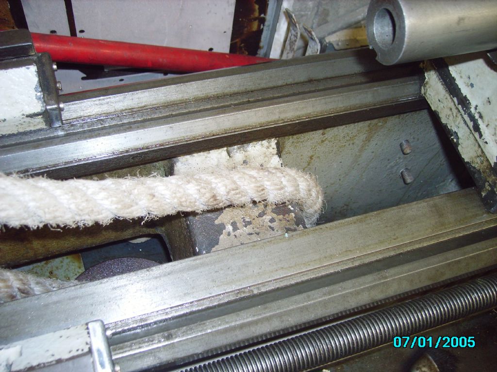
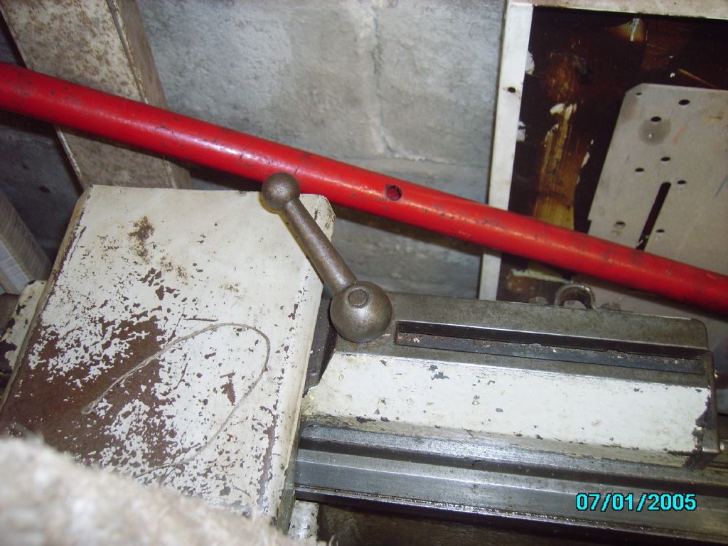
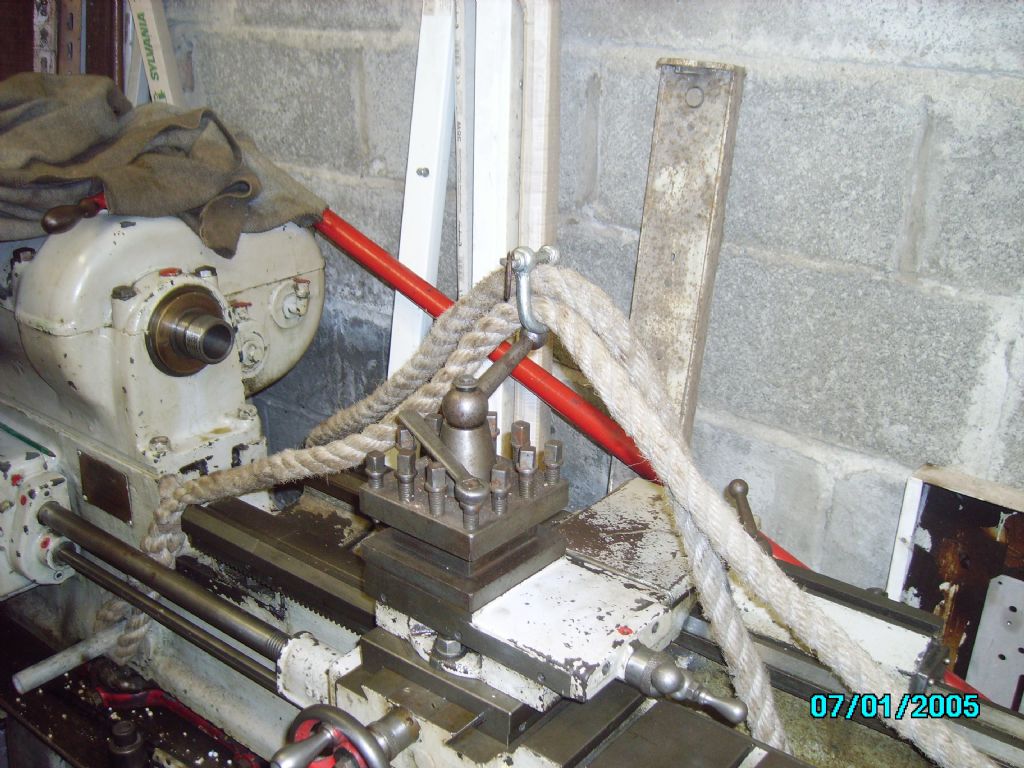
then I got my best rope strop and mocked up how I would lift the bed once the headstock was off and finnally the lifting point, putting the hook of the crane where the shackle is, just above the tool post.
you can then try a lift to see if it is balanced and move the carriage either way to achieve this, then lock it . My order of the day would be; Put the leg bolts back on, or when you try to lift the headstock it will lift the whole lathe if the headstock is stuck with paint. Remove the headstock, pallet it and trundle it away. free the legs from the concrete. Try a lift on the bed, get it balanced and lift the bed just clear of the legs. (now it geta "hairy" take out the legs and place the bed pallet over the legs of the engine crane, blocked up on timber baulks so the crane is not trapped under the pallet. Lower the bed to the pallet and strap it down. If you need to go out of a doorway to exit the shed, use the crane one end at a time to remove the baulks and lower pallet and bed onto rollers. once outside you can pick it up again and place it across the engine crane legs, leaving some weight on the crane, and trundle over the plywood sheets to the road. If you do it this way, you will not have to move the engine crane with the bed at height (ie to clear the legs) which is very risky. Having said all this, moving lathes at 300 miles range is easy |
| Phil Whitley | 29/09/2014 18:39:10 |
1533 forum posts 147 photos | Hi again, just to add, I also am assuming the drip tray is samwiched between the bed and the legs, you will see when you lift the bed, and once the bolts are clear it should just slide off. I wouldn't worry about the concrete too much Chris, looking at the pics, and at the feet on mine, there is not much depth at all, I think he has grouted round it just to stop it moving sideways. |
| Brian Wood | 29/09/2014 19:23:37 |
| 2742 forum posts 39 photos | Hello Phil and Chris, Phil I like that modified plan, it sounds very workable; keeping the weight low down is always best and it stops oscillations from building up. If some strong support, like breeze blocks, are moved in under the load while the legs come off that gives is a safety net for the poor sap grovelling about underneath releasing the bolts! Instead of using the crane to left each end of the bed in turn to get it out of the door, a good bar with hefty timber fulcrum might be easier. It avoids the hassle of getting the crane out of the doorway while the bed is taking up the space it needs. Flexing tailstock legs!!!!! Wow, are they not bolted on as well? I agree with you over the concrete/grout, I too feel sure it will break away with ease. If the leg was buried in it as in a block into a hole in the floor that would be quite different. Any thougths on floor bolts insde the headstock box? Just out of curiosity, is the headstock nose bore 3MT? your picture suggests nearer 4. I will be making Chris an alignment gauge from a Landrover 1/2 shaft, but can only go to 2MT for an accurate fit in my Myford and Chris will need to buy a suitable size drill sleeve. Chris Drill sleeve. I recommend someone like Cromwell Tools or MSC supply or a name like Rohm, it does need to be good quality and I would avoid the cheap imported versions, you have no way of testing it on receipt. If you weren't so far away I would be pestering to join the party! Brian |
| CHRISTOPHER MILLS 1 | 29/09/2014 19:53:33 |
152 forum posts 61 photos | Thanks gentleman, this sounds a very good, comprehensive and cunning plan. From the general state of the lathe, I would be extremely surprised to find anything stuck up by paint. I like the idea of not having to lift the lathe higher than it is, but just to lower it. The three point fixing looks sterling. Where can I buy a rope like yours, Phil, strong enough to lift it? Chains are horrendously expensive, and look like capable of easily damaging the lathe. Brian - I believe spindle bearing on the head is 3 Mt - tailstock 2 MT - according to Tony of Lathes. I would send my chauffeur up to pick you both up, but with the late recession I had to let him go! Best. Chris.
|
| Phil Whitley | 29/09/2014 20:38:49 |
1533 forum posts 147 photos | I would use slings rathey than rope, something like these, http://www.recovery-equipment.co.uk/strops-slings-lifting-double-single-simplex-duplex/strops-slings-lifting-double-single-simplex-duplex/269/d2000kg-4m-strop.html They don't stretch or twist like rope does. The rope was for "illustration purposes only) I don't like rope for lifting heavy stuff, much prefer strops/slings, or chains. Phil. |
| CHRISTOPHER MILLS 1 | 29/09/2014 21:11:47 |
152 forum posts 61 photos | Brian, There are no bolts in the plinth end, as the holes are on the outside of the box, and empty. I shall be surprised to find floor bolts in the tailstock end, but on Thursday (my next trip to Totton, Southampton), I hope to prove it. There is no power at the property, so I will be armed merely with hammer and cold chisel. Chris.
|
| Brian Wood | 30/09/2014 09:37:59 |
| 2742 forum posts 39 photos | Hello Chris, Phil has the 17 inch model, that has the 4MT head socket, I realised that after I posted my comment. Slings are good for this sort of work, as Phil says they don't stretch and being flat they have a broad face in contact with the job.. There was a time when a man of power and influence would have been able to dispatch a 'light' train to Southampton just for his personal use; like yourself I had to dispense with those services so I will have to watch from these distant sidelines! Bolting of feet at the tailstock end would have been a bad idea I think. The design choice would have been to install the lathe using the plinth as the primary location. The tailstock legs would act as props, packed up as needed to eqiualise the load on them. That way the bed is in a stress free condition, without any twist. When you finally get this on it's feet in the new location I do recommend bolting the plinth down for two reasons 1. The motor and it's mounting plate will impose a significant off centre toppling load 2 An out of balance job on the lathe could add to that and allow the whole thing to fall over backwards. My Myford lathe motor is hung out on a cantillever and the lathe needs bolting down to stop just that from happening Brian.
|
| Phil Whitley | 30/09/2014 19:38:25 |
1533 forum posts 147 photos | Hi all (or both?) Mine is the 13" model Brian, but it isnt the one illustrated on lathes.co.uk, which I assume is the very early model. Mine seems to be exactly like Chris's apart from small details (mine has a lever lock on the tailstock, though this could be a latter addition) The 17" has the motor actually inside the much larger foot. When I first saw mine on ebay, I was convinced it was a 17 untill I actually saw it in the flesh, it was the headstock pillar with the "cupboard door" (access to belt adjusring nut) that fooled me! Very valid comments about the weight of the motor and mounting hanging off the back, and also out of balance jobs. I will be aware of that when I install mine. Phil |
| neville rigg 1 | 01/10/2014 04:02:37 |
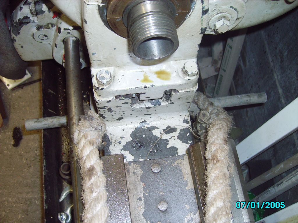
| 24 forum posts | Hi Chris, I trust that you are not going to use the shakle on the rope as the pic suggests, Get two slings and put the eyes on the ends on thee hook of the lift, the way you have it the rope is very likely to slip if the load is not evenly balanced, looking at the machine I get the impression that it is going to be heavier at the headstock end you would be much better with slings, these are available in various lengths and it may be easier to have two of different lengths in order to balance it better. A engineer supply company would be your best bet to obtain them and if you grovel you might be able to return them if they have not been used, check it out first, they may have skates for hire if your lucky.I used to remove and re-install ali extrusion presses which are a little bit heavier but the basic peinciples are the same, just take it slowly. Neville. |
| CHRISTOPHER MILLS 1 | 01/10/2014 05:40:44 |
152 forum posts 61 photos | Neville, Many thanks; the overall vote is for sling ties. Phil was demonstrating positioning with the rope. I can see how important it is to have the lathe held very tightly on the initial lift. The more I looked at chains the more I found it hard to imagine protecting the lathe from them. Chris.
|
| neville rigg 1 | 01/10/2014 06:08:48 |
| 24 forum posts | Chris, the trouble with chains is there is no warning before they go, I would never use them on any machinery, O.K. for steelwork and pipework. Neville. |
| CHRISTOPHER MILLS 1 | 06/10/2014 14:31:05 |
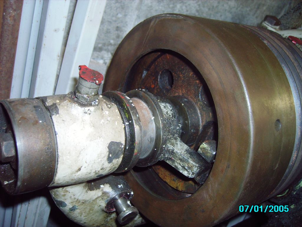
152 forum posts 61 photos | Second revisit to the CovMac: 4th Headstock bolt is now free, and the head is loose, ready for removal - I have secured it on two headstock bolts, because left loose it will topple off backwards, being very back heavy. Plinth is de-concreted, but tailstock end is harder: Beneath a concrete fillet lies a series of loose bricks - the tailstock end is higher, and the lathe's feet are about 2 inches off the floor of the shed. The lathe will have to be jacked at that end before completing it. I did not want it to drop two inches by overdoing it. Motor and mounting is very inaccessible, still, because the lathe is so pushed up against the wall - that will be tackled when I have the headstock removed, hopefully some time next week. I have removed all loose stuff, four spare chucks, and half a ton of cutting tools and assorted goodies, and a lapping plate. In the meantime here is a picture of the CovMac's clutch in more detail:
What is in the clutch mechanism? What can I expect to see? Under the top cover there are five vee grooves on the pulley wheel. The clutch is really quite big. I have disconnected the two vee drive belts from the motor. The lathe was reconditioned by the same firm which did Phil's; I.L. Berridge of Leicester. Mine was renovated by them in January 1955, using the same reference number as the War Ministry allocated the machine. There were comprehensive Machine Tool Orders in the Second World War, regulating use and ownership of machine tools. Chris.
Edited By CHRISTOPHER MILLS 1 on 06/10/2014 14:33:11 Edited By CHRISTOPHER MILLS 1 on 06/10/2014 14:34:14 Edited By CHRISTOPHER MILLS 1 on 06/10/2014 14:35:00 |
| Phil Whitley | 06/10/2014 21:15:16 |
1533 forum posts 147 photos |
Hi Chris, It is only since you started this project that I have looked at the clutch mechanism, it appears to push two pins into a series of holes spread around the V belt pulley. Whilst that is what I can see I think there must be a bit more too it than that, I will look tomorrow. Referring to your picture if you remove the pivot bolt from the clutch arm , and loosen the nuts with the sc4rew slots in the bolts, the clutch arm comes off. I will check the exact details tomorrow. I removed mine because it sticks out quite a lot and I didnt want to break it. It may be a malleable casting, it may not, just not worth the risk. Good progress and good news that the headstock is loose, well done that man! Phil |
| Brian Wood | 07/10/2014 16:47:33 |
| 2742 forum posts 39 photos | Hello Phil and Chris, I'll await your findings with interest. I've been correspoding with Chris by email lately, some of it abour beekeeping, but he was puzzled by the slotted head screws in the periphery of the drum that you can see in his photo. I wondered if they secured an inner liner of some sort, possibly even in asbestos as in brake shoes, but fashioned into a cone; into which a steel mating cone is pushed to engage drive. Then the visible grease bothered me so it may instead be a metal to metal cone, more in line with the sort of thing my shaper and Myford lathe have.. I am not much taken with the idea of pins being pushed into holes, hardly a smooth take up and very likely to shear off in use. So I share your suspicions that there are wonders to be revealed. This old lathe seems to be full of surprises; if you ever decide to strip off the screwcutting gearbox for any reason I have a list of questions on the internal details for resolution. I imagine the clutch thrust collar bears down on a carbon thrust pad as in early vehicle clutches, today ball thrust bearings do that duty.. We shall see what you find Regards Brian Edited By Brian Wood on 07/10/2014 16:49:51 |
| Phil Whitley | 07/10/2014 18:11:56 |
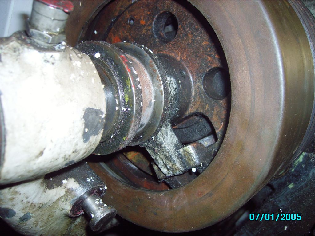
1533 forum posts 147 photos | Hi All, Brian, we were right! the clutch s far cleverer than pins or dogs. From what I can see, or rather more what I can feel when I operate it, there is some sort of spring loaded over-centre mechanism which pulls a plate over inside the drum. I an guesing at plate really, it could be a cone, whichever the take up is smooth and very positive, with no perceptable slip that I can create by hand. I all looks very straightforward to strip, as long as the contersunk screws come out of the drum! Mine also has a liberal coating of grease or oily gunk, but the lathe was working fine so i could be some sort of metal (bronze?) friction mateial. I have included two pics below (I hope). I have stopped trying to get the text and pics in order, it seems to make up its own mind where it is gong to put them, apparently regardless of the cursor postion. Pics show clutch in and out. Phil.
|
| Phil Whitley | 07/10/2014 18:14:06 |
1533 forum posts 147 photos | Or rather top pic is out and bottom one is iin (driving) Phil |
| Neil Wyatt | 07/10/2014 20:23:21 |
 19226 forum posts 749 photos 86 articles | > Chris, the trouble with chains is there is no warning before they go, I would never use them on any machinery, O.K. for steelwork and pipework. I once heard of someone deliberately disabling an old hand crane ... by cutting through one side of a chain link. Well meaning but incredibly stupid. Neil |
| Phil Whitley | 07/10/2014 22:06:59 |
1533 forum posts 147 photos | I understand your point about chains, but unless you are using a rust old lump of chain you found in a field, you are pretty safe! You should never lift with anything except the chain, rope or strop designed for that purpose, and it should of course be in good condition. Chains are very strong, and it is doubtfull you would snap a proper lifting chain unless you were attempting a lift like a traction engine. I have two hook chains sets from a blackhawk eurodozer car straigtening jig, the links are about 5/16 diameter steel and the hook is specially shaped to hook onto the chain to form a loop. One of them would lift the entire complete covmac with ease as they are rated at 20 tons! Like wise you hear horror stories about wire rope, but the golden rule is simply to use equipment that is in good condition and rated at well above the weight you are lifting, and if you see the filler twine coming out from between the stands of wire, RUN! Phil. |
| Brian Wood | 08/10/2014 10:07:54 |
| 2742 forum posts 39 photos | I have witnessed a Yorkshire Dales farmer using a very tired wire rope to drag out tree stumps using the rear hitch on a big 4WD tractor with 100 HP on the wheels. Tired barely describes this rope, it had broken strands all down it and was maybe down the core when I saw this. Needless to say I gave it a very wide berth indeed; the lamentable lack of imagination shown was really beyond belief. As Phil says, all that sort of tackle is OK when in good condition and in the example above he got away with it, but would that be the case another day? When the same man was pulling full grown sycamore trees for me to control the line of felling, I made damned sure it was my rope and chains that were used. Huddled down with a chain saw at the base the last thing I needed was for it to lurch back on me. Brian |

 , it is easy to not appreciate the full magnitude of problems you may have to deal with, you will be there, unfortunately, I will not. I am now seroiusly considering moving my covmac in bits, because I have to get it through a doorway, and I don't know if I have sufficient room to turn it round. with the legs on. What do you think to the above Brian?
Please login to post a reply.
Magazine Locator
Want the latest issue of Model Engineer or Model Engineers' Workshop? Use our magazine locator links to find your nearest stockist!
Sign up to our Newsletter
Sign up to our newsletter and get a free digital issue.
You can unsubscribe at anytime. View our privacy policy at www.mortons.co.uk/privacy
Latest Forum Posts
- hemingway ball turner
04/07/2025 14:40:26 - *Oct 2023: FORUM MIGRATION TIMELINE*
05/10/2023 07:57:11 - Making ER11 collet chuck
05/10/2023 07:56:24 - What did you do today? 2023
05/10/2023 07:25:01 - Orrery
05/10/2023 06:00:41 - Wera hand-tools
05/10/2023 05:47:07 - New member
05/10/2023 04:40:11 - Problems with external pot on at1 vfd
05/10/2023 00:06:32 - Drain plug
04/10/2023 23:36:17 - digi phase converter for 10 machines.....
04/10/2023 23:13:48 - More Latest Posts...
- View All Topics
Support Our Partners


Shopping Partners
Subscription Offer

Latest "For Sale" Ads
- Reeves** - Rebuilt Royal Scot by Martin Evans
by John Broughton
£300.00 - BRITANNIA 5" GAUGE James Perrier
by Jon Seabright 1
£2,500.00 - Drill Grinder - for restoration
by Nigel Graham 2
£0.00 - WARCO WM18 MILLING MACHINE
by Alex Chudley
£1,200.00 - MYFORD SUPER 7 LATHE
by Alex Chudley
£2,000.00 - More "For Sale" Ads...
Latest "Wanted" Ads
- D1-3 backplate
by Michael Horley
Price Not Specified - fixed steady for a Colchester bantam mark1 800
by George Jervis
Price Not Specified - lbsc pansy
by JACK SIDEBOTHAM
Price Not Specified - Pratt Burnerd multifit chuck key.
by Tim Riome
Price Not Specified - BANDSAW BLADE WELDER
by HUGH
Price Not Specified - More "Wanted" Ads...
Get In Touch!
Do you want to contact the Model Engineer and Model Engineers' Workshop team?
You can contact us by phone, mail or email about the magazines including becoming a contributor, submitting reader's letters or making queries about articles. You can also get in touch about this website, advertising or other general issues.
Click THIS LINK for full contact details.
For subscription issues please see THIS LINK.
Digital Back Issues


Donate

 Register
 Log-in
Model Engineer Magazine
- Percival Marshall
- M.E. History
- LittleLEC
- M.E. Clock

ME Workshop
- An Adcock
- & Shipley
- Horizontal
- Mill

Subscribe Now
- Great savings
- Delivered to your door

Pre-order your copy!
- Delivered to your doorstep!
- Free UK delivery!
All Forum Topics > Beginners questions > CovMac Lathes