Forum sponsored by:

Scale model Economy hit & miss engine builders wanted
I need to get my engine running
| Charles 2010 | 26/11/2010 17:49:41 |
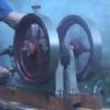 84 forum posts 54 photos | A chum of mine is designing a 555 timer strobe so that I can get a good idea as to when my engine is doing that sort of speed ..
If it is successfull I will let you know details via this forum ..
Regards Charles Edited By Charles 2010 on 26/11/2010 18:00:56 |
| John Wood1 | 27/11/2010 11:55:55 |
 116 forum posts | Well done Charles, it's certainly getting there and all credit to you. The governor spring needs to be lighter to run slower, and indeed to get it to open in the first place, I can run mine VERY slowly indeed and much less that 400rpm although 4 to 5 is certainly a decent working speed. I picked up a small electronic strobe off the internet, it's the type which triggers from a small piece of white reflective tape stuck onto the wheel, it all works fine and was not too expensive (about £20 as I remember). I thought about building one myself based on the 555 timer chip but felt my time was worth more to me so went for the easy commercial option.
Will you be trying it on gas at any time I wonder?
LA Services demo engine runs slowly but without hit & miss which, I agree is not the best way of demonstrating, I guess it's less likely to falter when running continuously so that's why they do it.
Have now moved house (at last) so no workshop yet. Will get back into it probably in the spring.
All the best, John |
| Charles 2010 | 27/11/2010 18:10:03 |
84 forum posts 54 photos | Thanks for the comments John.
the strip down revealed the follow ing problems:-
1. that the main bearing had been moving in their seats - solution - the oilers have been made with M5 connection and this has been taken right into the bearings to prevent rotation.
2. the big end had slight end float - solution - a slight filing of the end piece take up the slack
3. the speed lever did not allow operate - solution - much lighter spring used and the minimum position noted
and also the good points:-
1. that the piston is as good as new
2. that there is no wear noticed o nthe gudgeon pins and end caps
When all is bolted back down and photos taken it will have another run ...
Regards Charles |
| Andrew Johnston | 27/11/2010 20:46:33 |
 7061 forum posts 719 photos | Hi Charles, Congratulations on getting the engine to run! Although I have already part machined the carb to the published drawings, if you don't mind I'll half inch your design instead. It's a lot simpler. Thank you. Regards, Andrew |
| Charles 2010 | 27/11/2010 21:02:27 |
84 forum posts 54 photos | Hi Andrew
I put the design on the forum so that other can use it .. At the air entry end I did progressively bell out the end with 20 then 30 then 40 then 50 deg cuts which i hope you can make out from the pictures. So I bored the first angle as stated and the just went in from the end so the the edge is quite thin .. Again I hope that can be seen from the drawing .. I have also made a choke to go on the end ...
the integral non return vave works a treat but I do hope to make a bird feeder type fuel tank such that the level in the lower tank start just a small amount below the entry to the carb ... This is just thoughts at the momnet but the carb is proved.
If you want more detail let me know ..
Rgards Charles
Video can be seen here -- follow the links on the pages to Economy engine then video
Edited By Charles 2010 on 27/11/2010 21:03:50 |
| Charles 2010 | 27/11/2010 21:05:40 |
84 forum posts 54 photos | Posted by John Wood1 on 27/11/2010 11:55:55: I picked up a small electronic strobe off the internet, it's the type which triggers from a small piece of white reflective tape stuck onto the wheel, it all works fine and was not too expensive (about £20 as I remember).
Any more details you can give to lead me to the one you bought ...?? |
| Charles 2010 | 27/11/2010 21:52:57 |
84 forum posts 54 photos | This is an improved drawing showing the "bell mouth air entry" angle not important but create a smooth curve ...
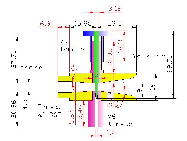 The lower unon is part of the the non return valve, and as such has a CROSS filed into the flat to allow fuel to flow past with a lower section that screws onto the M6 Thread with a small stainless steel ball bearing. Regards Chalres |
| Charles 2010 | 29/11/2010 18:09:01 |
84 forum posts 54 photos | All being well I will be making up a base to bring the crank up to about 23" from ground level, then may be add 4" wheels which will bring it to about 24" which should be a reasonable height from the gound for starting and running.
It is being made from the steel angle and square section I have laying around so it will be put to good use ...
Still think about the fuel tank !!!
Regards Charles |
| Andrew Johnston | 02/12/2010 10:14:20 |
7061 forum posts 719 photos | Hi Charles, Thanks for the updated carb drawing. I'm not sure I understand the purpose of the non-return valve. I assume that air drawn thru the carb causes fuel to be sucked from the tank? Does the non-return valve stop it running back? At what level do you think the fuel tank should be relative to the carb? I'm planning to TIG weld an external stainless steel fuel tank, so I'll have freedom to set it at what height I want. Regards, Andrew |
| Charles 2010 | 02/12/2010 10:33:31 |
84 forum posts 54 photos | According to all that I have read and been told the fuel entering a carb should be just below the exit point in the carb ( ie where the needle jet opening is.
So to achieve this the first way is to put a non return valve in the line so that the fuel that is sucked up stays there ready for the next entry into the cylinder.
An alternative is to have a float chamber adjacent to the carb with a needle to stop fuel entering when full
Another alternative is to use the chicken feed hopper idea where fuel only enters the feed section when previous fuel has been used and allows more fuel to enter
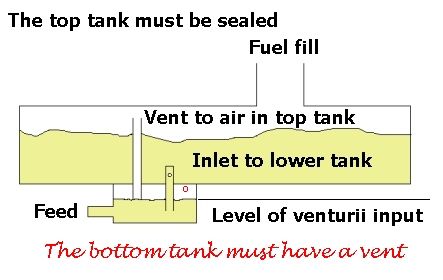 and lastly a small thin but long fuel tank placed at just below the level of the exit point to the carb.
What you want to avoid is for fuel to have to be sucked up into the carb all the time as the needle jet will need to be open further than necessary for the right amount of fuel to enter the carb and mix with air and this will lead to flooding of the engine.
I understand that the mix must be 14.2 to 14.9% fuel to air for ignition and this must be in vapour and not dropletts.
An external fuel tank sounds a good idea but at no time must the fuel in the tank be above the exit point of the carb else it will just flow out nor too far below other wise the mix will not be right as the carb has to do too much sucking up of fuel before vapourising.
I hope this has been fo some help you you .. Edited By Charles 2010 on 02/12/2010 10:42:39 |
| Andrew Johnston | 02/12/2010 10:53:33 |
7061 forum posts 719 photos | Hi Charles, Great stuff, thanks. I think I understand what is going on now. I'm not sure what the percentage of fuel to air is, but I do remember vaguely from my thermodynamics courses that the stoichiometric air/fuel mixture for petrol is approximately 14.7, by mass, for complete combustion. I think the best thing to do is make and fit the carb and then design the fuel tank to suit. I'm planning to mount the engine and ancillaries on a square piece of jig plate, so I also have some flexibility on the height at which I mount the engine. Regards, Andrew |
| Charles 2010 | 02/12/2010 11:17:42 |
84 forum posts 54 photos | Well I was in the right ball park ..
I have Googled and 14.7% is right ... well recalled !!!
Here is the stand I built on Tuesday before the "real" snow arrived !!!!
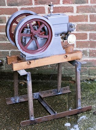 It is designed to bring the crank handle to about 24" from ground level. I may also fit it with wheels.
Regards Charles |
| Charles 2010 | 11/12/2010 15:16:17 |
84 forum posts 54 photos | With all the modifications made to the engine the most necessary one was to the hit and miss action in that I have taken the pushing shaft back so that the push shaft does not exit the rotation shaft until the balls start to fly then as the engine speed up the shaft causes the hit and miss action to take place ... All very satisfying but not caught on video as I was operating all the items my self .. BUT bad engineering on my part means that a new crank is needed as mentioned before even the pinning has not held things solid so I may try welding the crank ad a temporary measure. The big eng bearing is also showing slop ... so a new one of those also required ... Still progress has been made and 2011 should see the engine running well ... Thanks for all who have made most useful comments on this forum ... Happy Christmas and good engineering in 2011.. Charles |
| dixie | 11/12/2010 16:05:02 |
| 31 forum posts | Hello Charles 2010
To make a tapered fuel screw drill down the end of your threaded part then super glue a gramophone needle in job done, look on ebay for needles.
brian |
| Charles 2010 | 11/12/2010 20:20:05 |
84 forum posts 54 photos | The needle idea sound good.
I am pleased to say the re-vamped carb is now working very well but now have to work out a way to stop the vibration of the engine causing it to close. Probably I will work out a stop so that is fails to an open position and not closed position !!
Regards Charles |
| MichaelR | 12/12/2010 11:51:24 |
 528 forum posts 79 photos | Hi Charles,
You may have to think about balancing the flywheel on your engine to cut down the vibration, you can do this by removing some weight from the flywheel inner rim and diametrically opposite the crank pin, this can be a trial and error job. As in the picture
 Edited By Stick on 12/12/2010 11:52:17 |
| Charles 2010 | 12/12/2010 12:13:57 |
84 forum posts 54 photos | When I have made the new crank in 2011 Then I will be able to set about trying to balance the fly wheels as you suggest. in the mean time may be I can add some weight as done with car wheels !!!
Regards Charles |
| JasonB | 12/12/2010 13:54:22 |
 25215 forum posts 3105 photos 1 articles | You may also want to think about some balance weights on the crank webs
J |
| Charles 2010 | 12/12/2010 21:29:58 |
84 forum posts 54 photos | I have been considering why my key ways are not holding the flywheels and I have found this web site ..
Looking at the table it seems that the keyways for the Model Economy engine could take 6x6mm keys rather than as the plans suggest 4x4mm keys.
Am I reading the table correctly as a 6x6mm key is substantially bigger than a 4x4mm and may be the reason why I am getting s working loose.
Any comments please even to say I am totally wrong and 4x4mm is correct.
regards Charles |
| Keith Long | 12/12/2010 21:43:38 |
| 883 forum posts 11 photos | Hi Charles My personal feeling id that if the shaft is a suitable size for a 6x6 key then you won't loose anything by going for the bigger size. From my own (limited) experience with keys in a crankshaft (on a full size car) fit is all important. The key should be a GOOD snug fit in the shaft as any slackness will eventually lead to the key coming loose and damaging the shaft by fretting. I had this happen on a Peugeot 504 engine. Fortunately I was able to repair the shaft with stainless steel filled Devcon, and changing the pulley that was keyed to the shaft was an easy option. A new key fitted into the shaft with the Devcon, allowed plenty of time to set and 20,000 miles later all was still well. Also how are the other parts held to the shaft. If they can move against the key you are likely to end up with damage. Keith |
Please login to post a reply.
Magazine Locator
Want the latest issue of Model Engineer or Model Engineers' Workshop? Use our magazine locator links to find your nearest stockist!
Sign up to our Newsletter
Sign up to our newsletter and get a free digital issue.
You can unsubscribe at anytime. View our privacy policy at www.mortons.co.uk/privacy
Latest Forum Posts
- hemingway ball turner
04/07/2025 14:40:26 - *Oct 2023: FORUM MIGRATION TIMELINE*
05/10/2023 07:57:11 - Making ER11 collet chuck
05/10/2023 07:56:24 - What did you do today? 2023
05/10/2023 07:25:01 - Orrery
05/10/2023 06:00:41 - Wera hand-tools
05/10/2023 05:47:07 - New member
05/10/2023 04:40:11 - Problems with external pot on at1 vfd
05/10/2023 00:06:32 - Drain plug
04/10/2023 23:36:17 - digi phase converter for 10 machines.....
04/10/2023 23:13:48 - More Latest Posts...
- View All Topics
Support Our Partners


Shopping Partners
Subscription Offer

Latest "For Sale" Ads
- Reeves** - Rebuilt Royal Scot by Martin Evans
by John Broughton
£300.00 - BRITANNIA 5" GAUGE James Perrier
by Jon Seabright 1
£2,500.00 - Drill Grinder - for restoration
by Nigel Graham 2
£0.00 - WARCO WM18 MILLING MACHINE
by Alex Chudley
£1,200.00 - MYFORD SUPER 7 LATHE
by Alex Chudley
£2,000.00 - More "For Sale" Ads...
Latest "Wanted" Ads
- D1-3 backplate
by Michael Horley
Price Not Specified - fixed steady for a Colchester bantam mark1 800
by George Jervis
Price Not Specified - lbsc pansy
by JACK SIDEBOTHAM
Price Not Specified - Pratt Burnerd multifit chuck key.
by Tim Riome
Price Not Specified - BANDSAW BLADE WELDER
by HUGH
Price Not Specified - More "Wanted" Ads...
Get In Touch!
Do you want to contact the Model Engineer and Model Engineers' Workshop team?
You can contact us by phone, mail or email about the magazines including becoming a contributor, submitting reader's letters or making queries about articles. You can also get in touch about this website, advertising or other general issues.
Click THIS LINK for full contact details.
For subscription issues please see THIS LINK.
Digital Back Issues


Donate

 Register
 Log-in
Model Engineer Magazine
- Percival Marshall
- M.E. History
- LittleLEC
- M.E. Clock

ME Workshop
- An Adcock
- & Shipley
- Horizontal
- Mill

Subscribe Now
- Great savings
- Delivered to your door

Pre-order your copy!
- Delivered to your doorstep!
- Free UK delivery!
All Forum Topics > I/C Engines > Scale model Economy hit & miss engine builders wanted