Member postings for Charles 2010
Here is a list of all the postings Charles 2010 has made in our forums. Click on a thread name to jump to the thread.
| Thread: Scale model Economy hit & miss engine builders wanted |
| 22/12/2010 23:29:06 |
Well today the engine had a nice run .... The carb setting was found to be a bit rich so it was turned down a little but this ment that the engine did not pick up after a miss .... So I must look into the chicken feed tank arangement mentioned previously...
The spring for the speed control is back to the original one again and now that the engine is well past if first hour of runing gives good responce.
I am going to change the water drain to a right angle bend and bung to make draining after a run easier.
When that is all done and the engine proved to still run well I will be fitting a generator that I have been loaned with the aim that the electricity generated will run my "G Scale" garden railway ... Of course there will need to be a control box but let's get it generating first. If that fails then I am thinking of making a water pump to supply water to a garden feature which would also have to be made !!!! |
| 18/12/2010 19:14:58 |
Well the light spring is too light so the speed control has to be at MAX to keep the engine running but at least I have something to work on .
The engine was run for about 20 minutes to day and all went well. I was able to use a engine ignition strobe light and my markings indicated ignition 5 deg AFTER TDC .. So the engine may run even better with the ignition move to TDC or a little before as suggested in the plans 8 to 12 deg BTDC.
Still too cold and family here so that will be sorted another day.
The revised keyways are holding firm as they are of the Gib type I think it is called and driven in tigtly but still with a space to be able to remove if needed ...
Regards Charles |
| 17/12/2010 12:17:13 |
The engine run this morning revealed that even adding the small amount of additional weight to the web, as shown in the picture a few posts back, considerably reduced the vibraton to an extent that is very tolerable and I can not press on with improving other items :-
1. the slow running it is still too fast
2. checking the carb as sometimes the fuel line empties so the non return valve is not working properly
3. drill small holes in the oil cap to allow them to vent which I missed noting was on the drawing.
4. ETC ETC
Regards Charles Edited By Charles 2010 on 17/12/2010 12:19:23 |
| 17/12/2010 10:14:52 |
Hi Jason
Yes all coming together ...
This is an amazing forum with so much information coming together in a relatively short time and the fact that members are prepared to share their knowledge with others.
Regards Charles |
| 17/12/2010 00:57:47 |
Thank you for confirming what I was told today ...
It is so nice when ideas are confirmed and one is not then totally in the dark going forwards.
I was told about the 90 out situation but did not fully comprehend it until your explanation clarified it for me.
I will take into account your comments on keeping things balanced each side of the piston something I had not thought about..
Below is the link to a short video of the engine runing as of 14th but it wil be tried again tomorrow with the experimental balance weights and I hope also take some video.
Regards Charles
|
| 16/12/2010 22:03:59 |
Now here is an interesting distilation of a discussion I had this morning:-
Balancing a single cylinder engine.
I have been told by a friend's at the Bredgar and Wormshill Light Railway that it is a fact is that it is IMPOSSIBLE to balance a single-cylinder engine. The best that can be done is a compromise. This is the suggestion :- Locate a set of digital scales. I am guessing that if you weighed the big end of the crank with the mass attached it would give one a starting point as to the mass required.
I know I am re-inventing the wheel but this is what the chaps must have done years and years ago (1910 ??)
Has anyone tried this or seen the similar set of instruction on the web
http://www.prestwich.ndirect.co.uk/technical_balancing.htm as I saw this afternoon and it matches almost exactly what I was told (may be it is a standard practice)? |
| 16/12/2010 21:48:28 |
I do appreciate the comments about using the flywheel to balance the crank but it has also been suggested to me that to balance components is also and acceptable method.
So with that in mind and in the essence of discovery I have decided to extand the webs and use the extensions in an effort to effect balance.
First try is shown.
 The engine will be run in the morning. Regards Charles
|
| 14/12/2010 11:06:41 |
Posted by Stick on 12/12/2010 11:51:24:
You may have to think about balancing the flywheel on your engine to cut down the vibration, you can do this by removing some weight from the flywheel inner rim and diametrically opposite the crank pin, this can be a trial and error job. As in the picture
 Are you indicating that the balancing should be done to take account of the crankshaft and the reciprocating weight of the con rod and piston as well as the flywheels or does one balance the flywheels alone ???
regards Charles
|
| 13/12/2010 17:44:08 |
I have re-thought the keys and I do not think it will be possible to adopt 6x6mm as this may result in failure of the gear on the crankshaft as there is not much metal left with a 4x4mm keys way.
Regards Charles |
| 13/12/2010 17:41:55 |
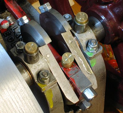
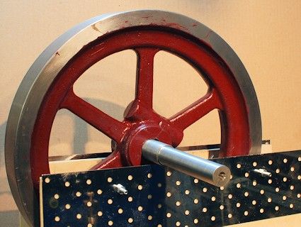
Balancing of the flywheels is completed by using the crude but effective set up. They now rotate right across the 12" of metal edge with only a gently push. The holes are driled in the top ede inner side as there was not sufficient material to drill where painted red. Sorry about the paint smudges I will clean then off one day !!!
 It will be interesting to see if the amount of vibration is reduced when next run.
Regards Charles |
| 12/12/2010 22:48:01 |
The other parts are only held on by the key being tapered but I am to use a parallel keyway and grub screw as an alternative. |
| 12/12/2010 22:45:45 |
Hi Keith
That is most helpfull from your experience and I consider that machining something bigger should be easier on tollerence than the smaller keyway.
I have today been making a new key as a better fit than the old one so I will see how that goes first and then have the option of making the key way bigger if it is not an improvement.
Regards Charles |
| 12/12/2010 21:29:58 |
I have been considering why my key ways are not holding the flywheels and I have found this web site ..
Looking at the table it seems that the keyways for the Model Economy engine could take 6x6mm keys rather than as the plans suggest 4x4mm keys.
Am I reading the table correctly as a 6x6mm key is substantially bigger than a 4x4mm and may be the reason why I am getting s working loose.
Any comments please even to say I am totally wrong and 4x4mm is correct.
regards Charles |
| 12/12/2010 12:13:57 |
When I have made the new crank in 2011 Then I will be able to set about trying to balance the fly wheels as you suggest. in the mean time may be I can add some weight as done with car wheels !!!
Regards Charles |
| 11/12/2010 20:20:05 |
The needle idea sound good.
I am pleased to say the re-vamped carb is now working very well but now have to work out a way to stop the vibration of the engine causing it to close. Probably I will work out a stop so that is fails to an open position and not closed position !!
Regards Charles |
| 11/12/2010 15:16:17 |
With all the modifications made to the engine the most necessary one was to the hit and miss action in that I have taken the pushing shaft back so that the push shaft does not exit the rotation shaft until the balls start to fly then as the engine speed up the shaft causes the hit and miss action to take place ... All very satisfying but not caught on video as I was operating all the items my self .. BUT bad engineering on my part means that a new crank is needed as mentioned before even the pinning has not held things solid so I may try welding the crank ad a temporary measure. The big eng bearing is also showing slop ... so a new one of those also required ... Still progress has been made and 2011 should see the engine running well ... Thanks for all who have made most useful comments on this forum ... Happy Christmas and good engineering in 2011.. Charles |
| 02/12/2010 11:17:42 |
Well I was in the right ball park ..
I have Googled and 14.7% is right ... well recalled !!!
Here is the stand I built on Tuesday before the "real" snow arrived !!!!
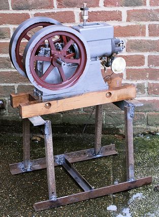 It is designed to bring the crank handle to about 24" from ground level. I may also fit it with wheels.
Regards Charles |
| 02/12/2010 10:33:31 |
According to all that I have read and been told the fuel entering a carb should be just below the exit point in the carb ( ie where the needle jet opening is.
So to achieve this the first way is to put a non return valve in the line so that the fuel that is sucked up stays there ready for the next entry into the cylinder.
An alternative is to have a float chamber adjacent to the carb with a needle to stop fuel entering when full
Another alternative is to use the chicken feed hopper idea where fuel only enters the feed section when previous fuel has been used and allows more fuel to enter
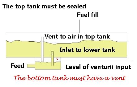 and lastly a small thin but long fuel tank placed at just below the level of the exit point to the carb.
What you want to avoid is for fuel to have to be sucked up into the carb all the time as the needle jet will need to be open further than necessary for the right amount of fuel to enter the carb and mix with air and this will lead to flooding of the engine.
I understand that the mix must be 14.2 to 14.9% fuel to air for ignition and this must be in vapour and not dropletts.
An external fuel tank sounds a good idea but at no time must the fuel in the tank be above the exit point of the carb else it will just flow out nor too far below other wise the mix will not be right as the carb has to do too much sucking up of fuel before vapourising.
I hope this has been fo some help you you .. Edited By Charles 2010 on 02/12/2010 10:42:39 |
| 29/11/2010 18:09:01 |
All being well I will be making up a base to bring the crank up to about 23" from ground level, then may be add 4" wheels which will bring it to about 24" which should be a reasonable height from the gound for starting and running.
It is being made from the steel angle and square section I have laying around so it will be put to good use ...
Still think about the fuel tank !!!
Regards Charles |
| 27/11/2010 21:52:57 |
This is an improved drawing showing the "bell mouth air entry" angle not important but create a smooth curve ...
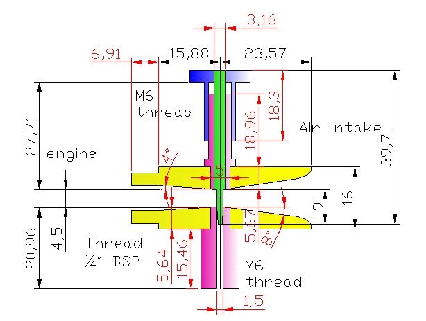 The lower unon is part of the the non return valve, and as such has a CROSS filed into the flat to allow fuel to flow past with a lower section that screws onto the M6 Thread with a small stainless steel ball bearing. Regards Chalres |
Magazine Locator
Want the latest issue of Model Engineer or Model Engineers' Workshop? Use our magazine locator links to find your nearest stockist!
Sign up to our Newsletter
Sign up to our newsletter and get a free digital issue.
You can unsubscribe at anytime. View our privacy policy at www.mortons.co.uk/privacy
Latest Forum Posts
- hemingway ball turner
04/07/2025 14:40:26 - *Oct 2023: FORUM MIGRATION TIMELINE*
05/10/2023 07:57:11 - Making ER11 collet chuck
05/10/2023 07:56:24 - What did you do today? 2023
05/10/2023 07:25:01 - Orrery
05/10/2023 06:00:41 - Wera hand-tools
05/10/2023 05:47:07 - New member
05/10/2023 04:40:11 - Problems with external pot on at1 vfd
05/10/2023 00:06:32 - Drain plug
04/10/2023 23:36:17 - digi phase converter for 10 machines.....
04/10/2023 23:13:48 - More Latest Posts...
- View All Topics
Support Our Partners


Shopping Partners
Subscription Offer

Latest "For Sale" Ads
- Reeves** - Rebuilt Royal Scot by Martin Evans
by John Broughton
£300.00 - BRITANNIA 5" GAUGE James Perrier
by Jon Seabright 1
£2,500.00 - Drill Grinder - for restoration
by Nigel Graham 2
£0.00 - WARCO WM18 MILLING MACHINE
by Alex Chudley
£1,200.00 - MYFORD SUPER 7 LATHE
by Alex Chudley
£2,000.00 - More "For Sale" Ads...
Latest "Wanted" Ads
- D1-3 backplate
by Michael Horley
Price Not Specified - fixed steady for a Colchester bantam mark1 800
by George Jervis
Price Not Specified - lbsc pansy
by JACK SIDEBOTHAM
Price Not Specified - Pratt Burnerd multifit chuck key.
by Tim Riome
Price Not Specified - BANDSAW BLADE WELDER
by HUGH
Price Not Specified - More "Wanted" Ads...
Get In Touch!
Do you want to contact the Model Engineer and Model Engineers' Workshop team?
You can contact us by phone, mail or email about the magazines including becoming a contributor, submitting reader's letters or making queries about articles. You can also get in touch about this website, advertising or other general issues.
Click THIS LINK for full contact details.
For subscription issues please see THIS LINK.
Digital Back Issues


Donate

 Register
 Log-in
Model Engineer Magazine
- Percival Marshall
- M.E. History
- LittleLEC
- M.E. Clock

ME Workshop
- An Adcock
- & Shipley
- Horizontal
- Mill

Subscribe Now
- Great savings
- Delivered to your door

Pre-order your copy!
- Delivered to your doorstep!
- Free UK delivery!