Forum sponsored by:

Stuart Twin Victoria (Princess Royal) Mill Engine
| Dr_GMJN | 05/04/2021 21:19:05 |
 1602 forum posts | Posted by JasonB on 05/04/2021 19:13:13:
As you will need to set the tool to desired radius plus half the bar diameter turning the area around the hole true ensured that the half diameter is actually half diameter not what half the bar is from the lathe axis. I think mine have a length approx equal to the bar dia turned true equalised about the hole Edited By JasonB on 05/04/2021 19:14:40 Don’t you turn the bore until it cleans up, measure it, and increment the tool outwards by half the difference to final diameter? I can see why a flat would make tool extension measurement more accurate, but not how turning cylindrical would help, unless it’s for absolute rather than relative measurement? |
| JasonB | 06/04/2021 07:46:25 |
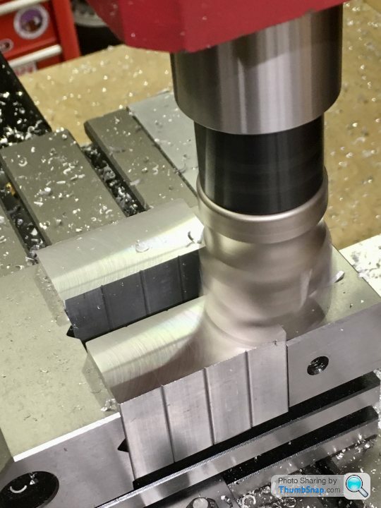
 25215 forum posts 3105 photos 1 articles | You can do it either way but having the section of bar true to the axis means it's there ready to make use of, also some of my bars are from quite rough hot rolled material so you would be measuring on an uneven surface which won't be very consistent. As for overlength bar I sometimes drive with the chuck and just support the tailstock end with the ctr so you can put more of the bar into the chuck if it's too long but it does save having to keep making bars when the next longer job comes along. |
| Dr_GMJN | 06/04/2021 19:47:17 |
1602 forum posts | Posted by JasonB on 06/04/2021 07:46:25:
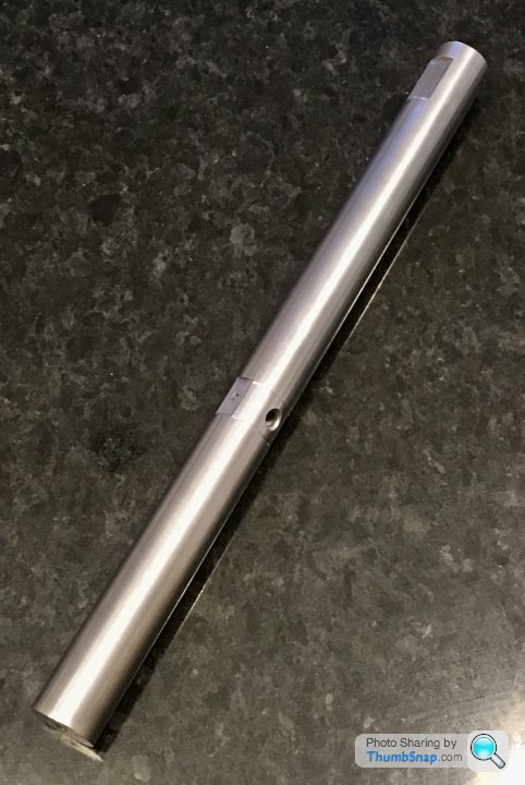
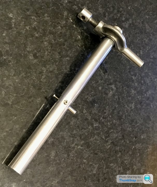
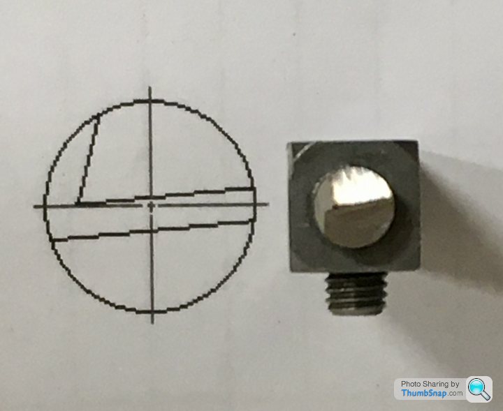
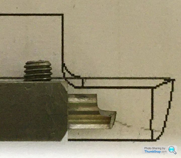
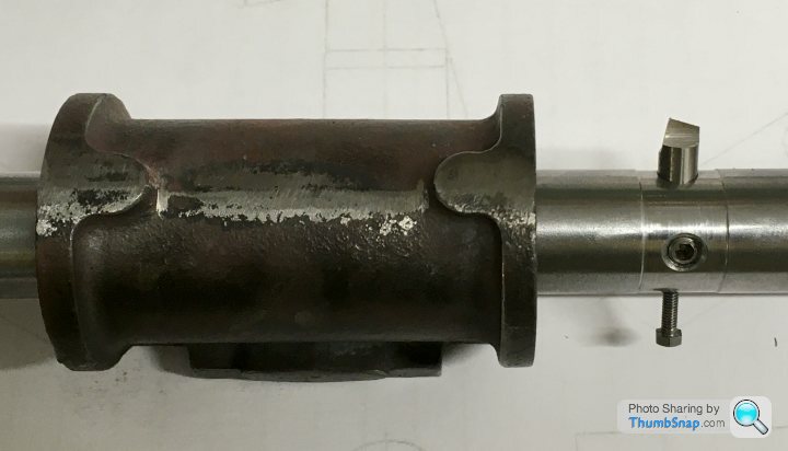
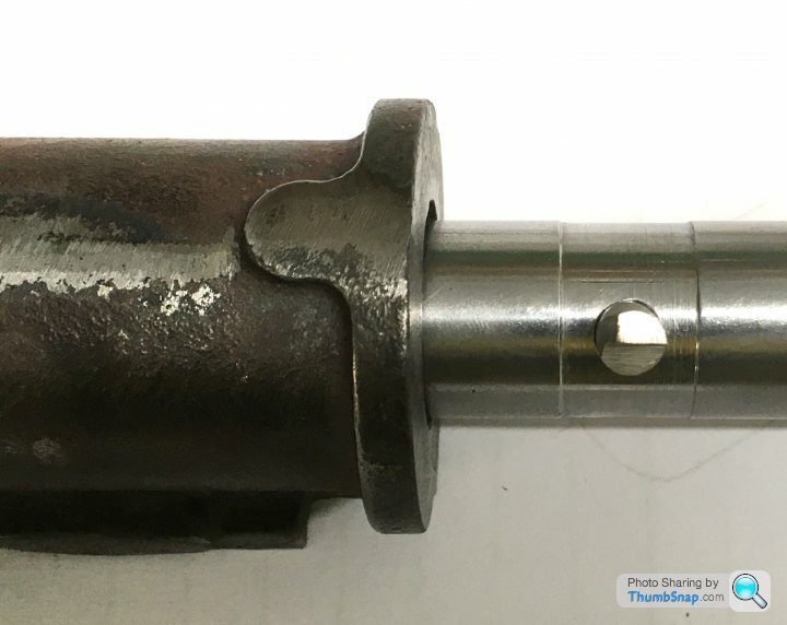
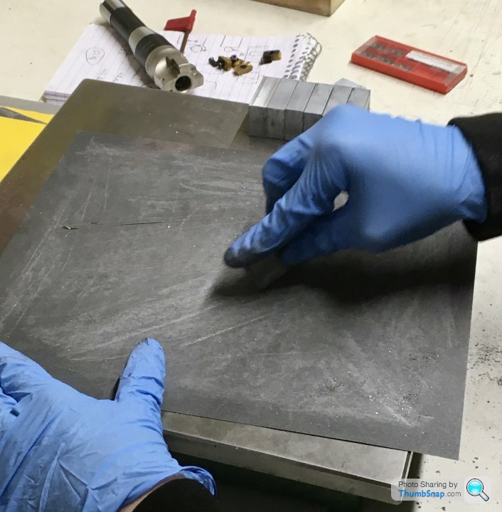
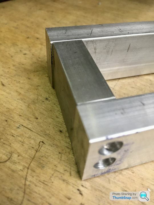
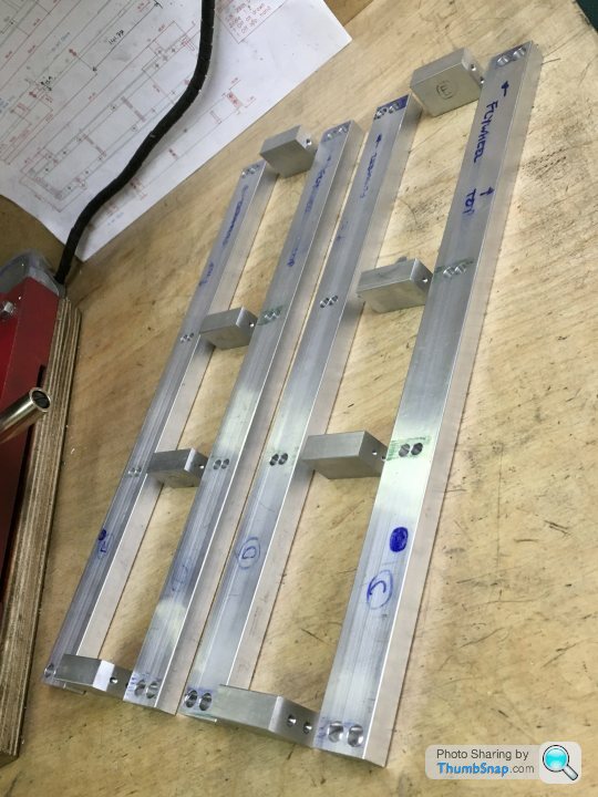
You can do it either way but having the section of bar true to the axis means it's there ready to make use of, also some of my bars are from quite rough hot rolled material so you would be measuring on an uneven surface which won't be very consistent. As for overlength bar I sometimes drive with the chuck and just support the tailstock end with the ctr so you can put more of the bar into the chuck if it's too long but it does save having to keep making bars when the next longer job comes along. Ok understood, thanks. So this is the first attempt. I did shorten it a bit - I can't see doing anything longer than the P.R. cylinders, and wanted to maximise stiffness. I've still got a couple of inches each side of the cylinder to play with: |
| Dr_GMJN | 11/04/2021 13:09:25 |
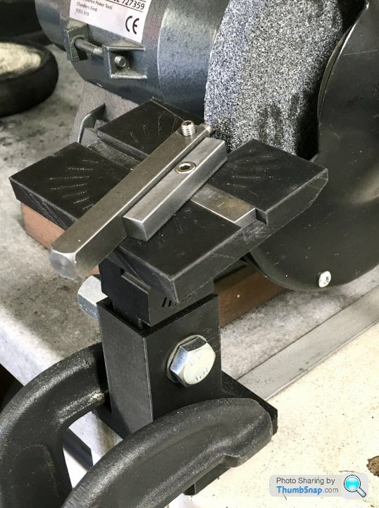
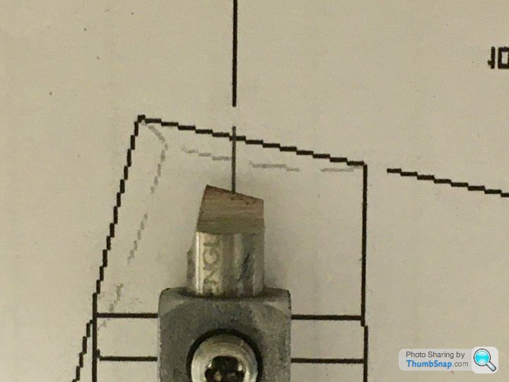
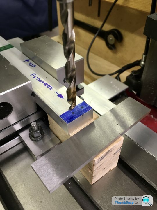
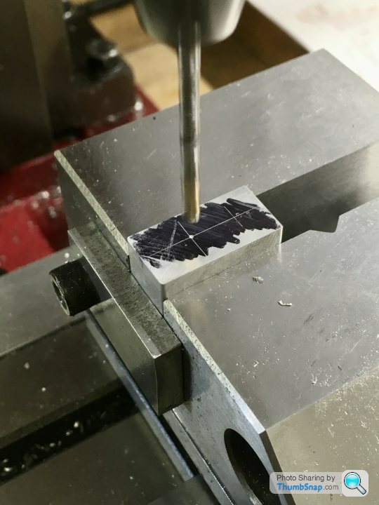
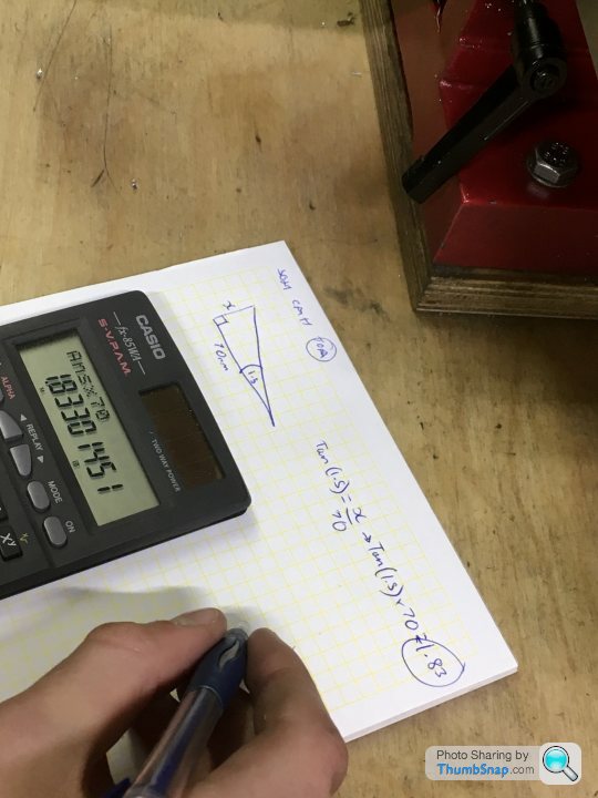
1602 forum posts | So I 3D printed a grinding jig, which I temporarily fitted in front of the bench grinder. I've graduated the angle markers at 10 degrees (they still need filling with white Milliput), and I'm hoping absolute accuracy isn't essential for this: Edited By Dr_GMJN on 11/04/2021 13:10:51 |
| JasonB | 11/04/2021 15:02:07 |
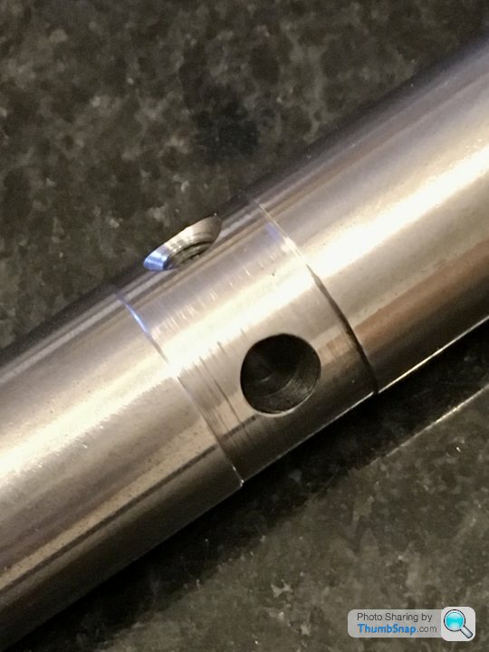
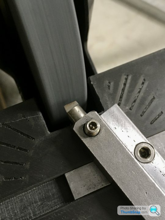
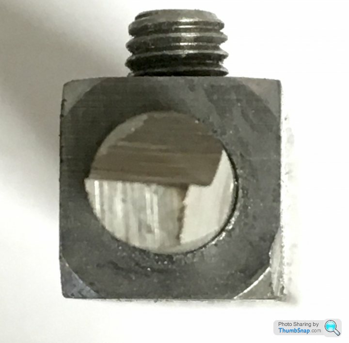
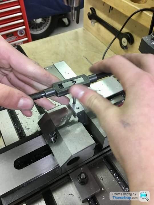
25215 forum posts 3105 photos 1 articles | Looks about right. Just make sure that the bottom of the tool arrowed in blue does not rub against the edge of the hole
Its the arrowed edge that does the cutting and that's the one you could give a run to with a diamond slip
Best to avoid using teh side of teh wheel if you can |
| Dr_GMJN | 11/04/2021 17:23:12 |
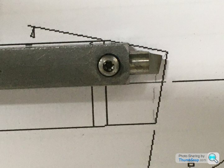
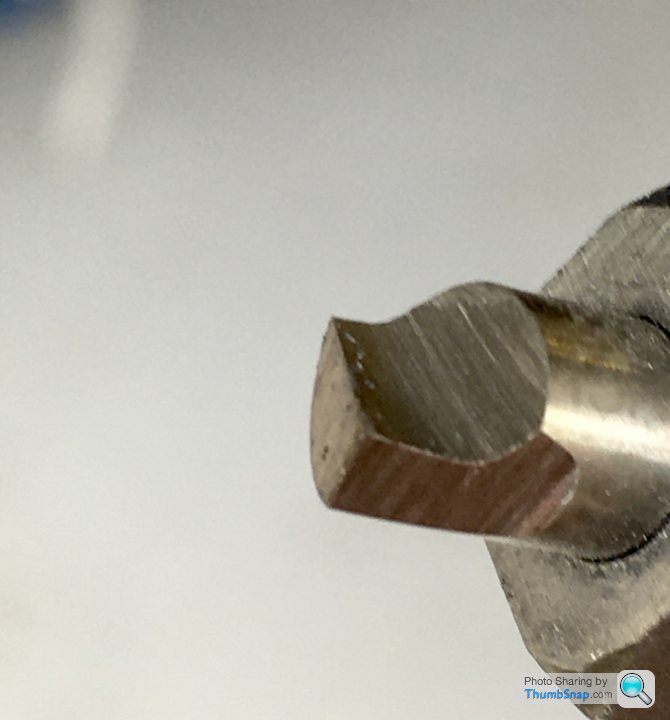
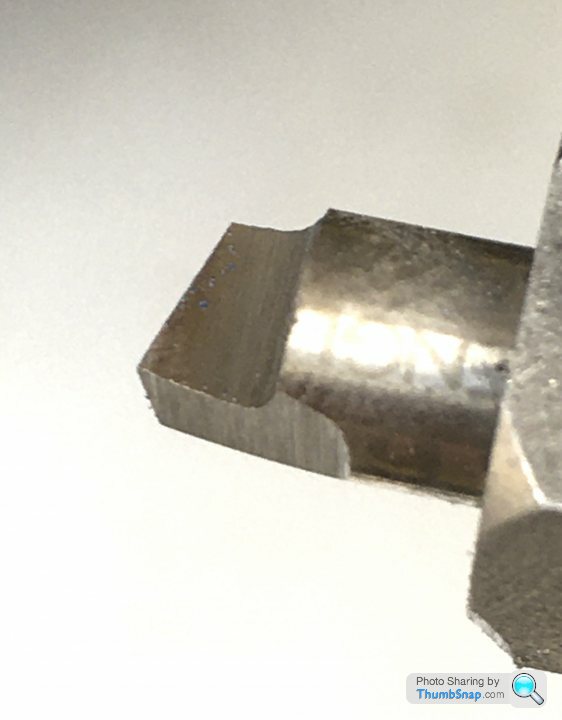
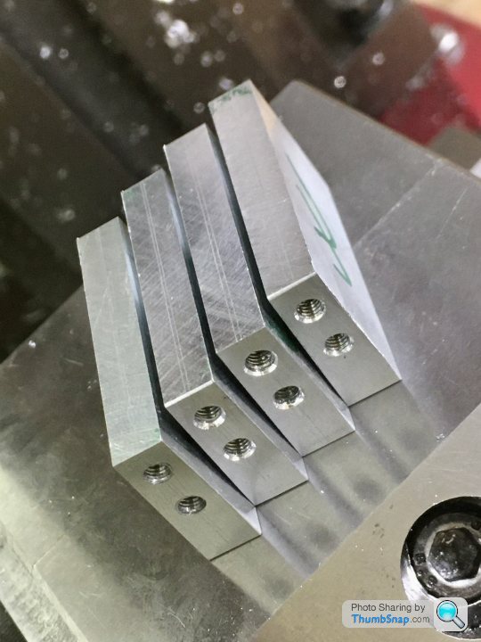
1602 forum posts | OK thanks Jason. So I'll make a couple more for good luck, touch the edge up with the diamond file, and also grind them to the correct length. On the last photo I posted, should the tool be rotated anti-clockwise slightly? I noticed the flat behind the cutting edge was angled down in the grinding drawing, but obviously you can orientate it how you want in the bar. Just got to do some car work this week, then I can finally make a start on this one. |
| JasonB | 11/04/2021 17:33:00 |
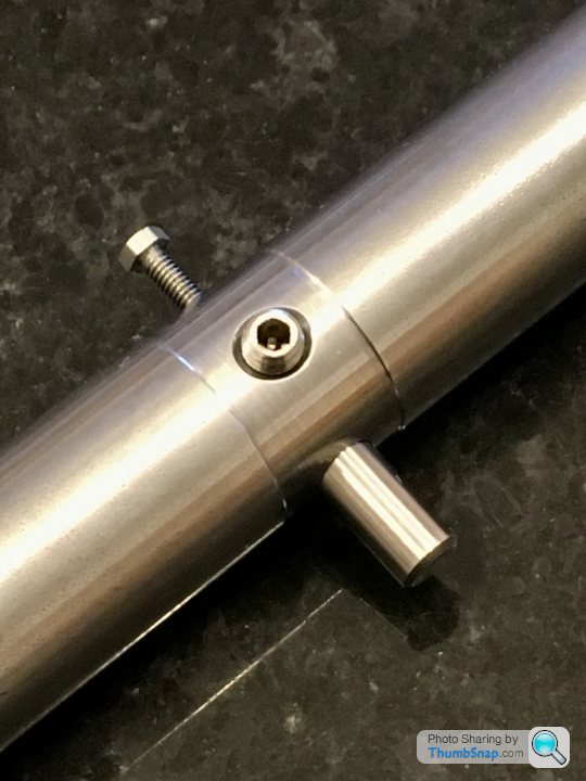
25215 forum posts 3105 photos 1 articles | Yes you want the top face sloping down slightly from the cutting edge as shown in green but make sure the red clearance angle is not lost as you rotate it, you want both to be about 5degrees
|
| Dr_GMJN | 11/04/2021 21:08:18 |
1602 forum posts | OK. when filing the edges, am I aiming for a sharp angle, with no edge or tip radius at all? Also, how long will the bit stay sharp? Should I re-file it after every cut, or perhaps before the final couple of cuts? Thanks. |
| JasonB | 12/04/2021 06:57:17 |
25215 forum posts 3105 photos 1 articles | I don't round mine. Yes once you are close give it a lick with the diamond so it's good and sharp for the last couple of cuts. |
| Dr_GMJN | 12/04/2021 20:00:24 |
1602 forum posts | Posted by JasonB on 12/04/2021 06:57:17:
I don't round mine. Yes once you are close give it a lick with the diamond so it's good and sharp for the last couple of cuts. Ok thanks. |
| Ramon Wilson | 12/04/2021 20:48:11 |
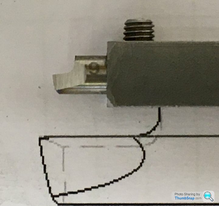
 1655 forum posts 617 photos | Hi Doc , been out of it for a few days (plastic distraction) so only just caught up with your progress. Nice work on the boring bar and you initial tool grinding. You might find a holder made from round bar more beneficial in creating angles but those you've got so far look just fine. I would use the sharp tip as per the last image for getting under the skin but for a really good finish 'off the tool' on the last ten thou or so I'd grind (not file) a nice radius on that corner. Keep the speed and feed well down for best results. Looking good - go for it Ramon |
| Dr_GMJN | 12/04/2021 22:03:25 |
1602 forum posts | Posted by Ramon Wilson on 12/04/2021 20:48:11:
Hi Doc , been out of it for a few days (plastic distraction) so only just caught up with your progress. Nice work on the boring bar and you initial tool grinding. You might find a holder made from round bar more beneficial in creating angles but those you've got so far look just fine. I would use the sharp tip as per the last image for getting under the skin but for a really good finish 'off the tool' on the last ten thou or so I'd grind (not file) a nice radius on that corner. Keep the speed and feed well down for best results. Looking good - go for it Ramon Thanks Ramon. I’ve taken a week off work for gardening and changing the rear brakes on the car. Unfortunately the easiest way to change inboard brake callipers is to remove the entire IRS. Got it removed today with the boy helping, next up is swapping the pots and re-fitting without getting squashed. After that’s done, it’ll be full steam ahead on the P.R., although I’m still battling with an Airfix Swordfish. Shame they decided to put a massive pocket under the upper wing, that results in some subtle but very difficult to remove sink marks. It’s already been in caustic soda once... Edited By Dr_GMJN on 12/04/2021 22:15:04 |
| Dr_GMJN | 09/05/2021 21:21:58 |
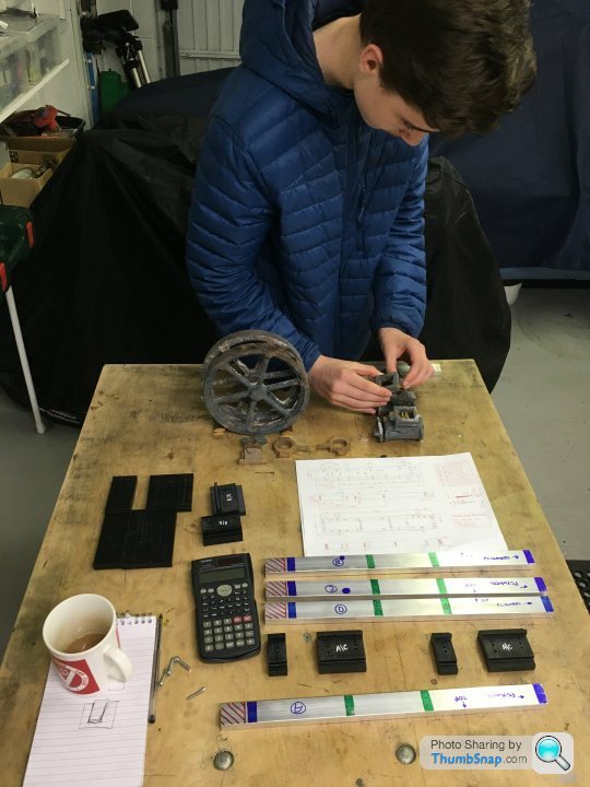
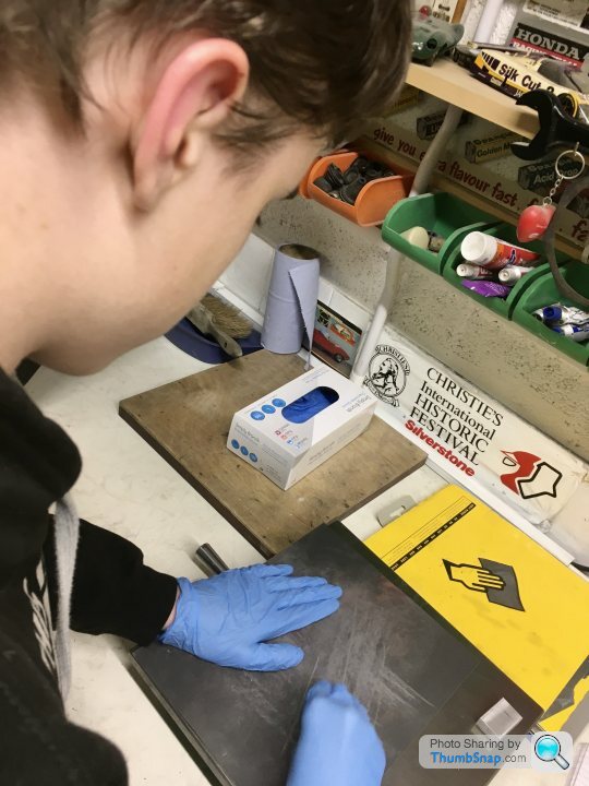
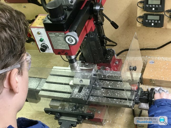
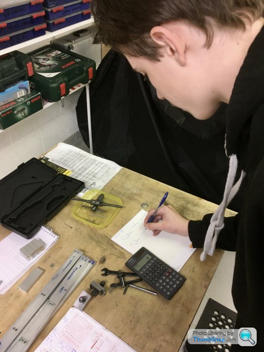
1602 forum posts | So it’s the one year anniversary of starting the 10V, so I made a start on this one. This time with some help from my son: |
| JasonB | 10/05/2021 06:55:20 |
25215 forum posts 3105 photos 1 articles | Good to see this one underway. |
| Dominic Bramley | 10/05/2021 08:53:45 |
| 60 forum posts 1 photos | +1 : I've been looking forward to seeing this build |
| Dr_GMJN | 10/05/2021 22:08:08 |
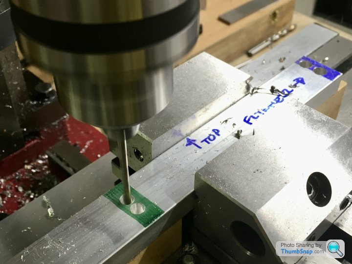
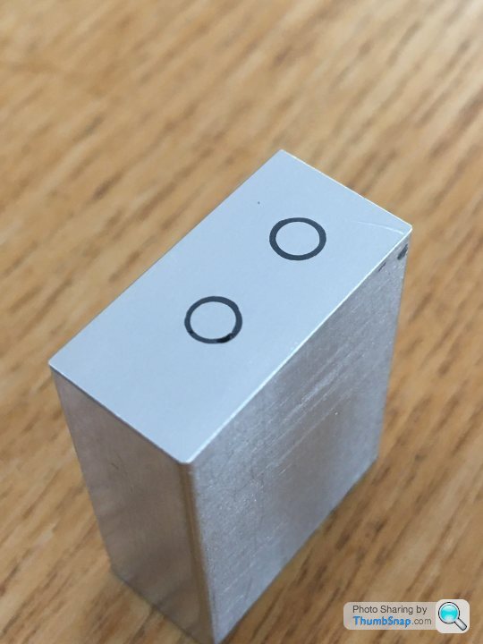
1602 forum posts | Thanks both. Got the holes drilled and counterbored tonight; they all match - so far. |
| Dr_GMJN | 12/05/2021 20:43:43 |
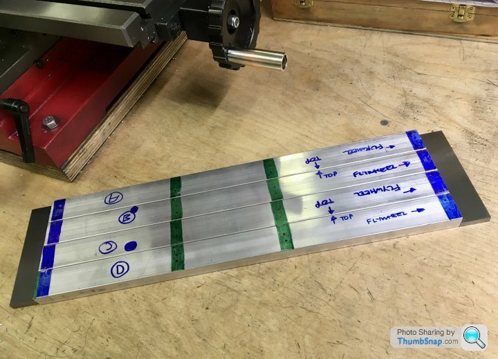
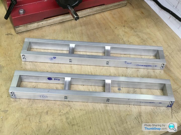
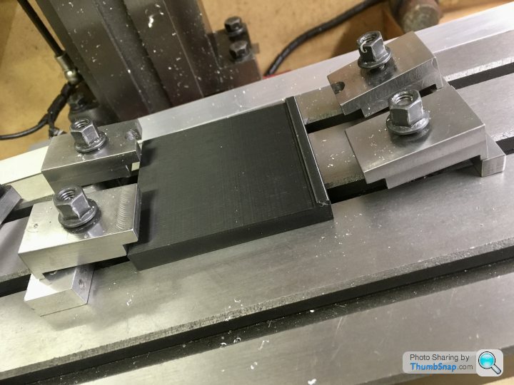
1602 forum posts | Decided to get on with the bed cross-pieces and ends. First job: saw 8x blocks a bit oversized, and de-burr: |
| Dr_GMJN | 13/05/2021 23:05:05 |
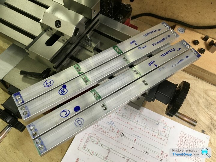
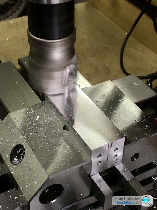
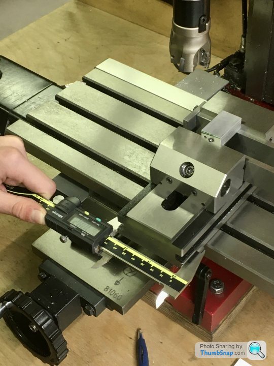
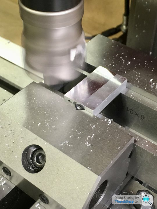
1602 forum posts | So this evening’s job was machining the middle bed spacers to thickness: |
| JasonB | 14/05/2021 07:04:52 |
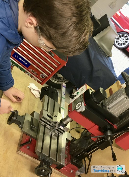
25215 forum posts 3105 photos 1 articles | You are both making good progress, just watch those hoodie strings around machines. |
| Dr_GMJN | 14/05/2021 07:23:02 |
1602 forum posts | Posted by JasonB on 14/05/2021 07:04:52:
You are both making good progress, just watch those hoodie strings around machines. Thanks Jason - very good point about the strings. I should have noticed that before now. |


Please login to post a reply.
Magazine Locator
Want the latest issue of Model Engineer or Model Engineers' Workshop? Use our magazine locator links to find your nearest stockist!
Sign up to our Newsletter
Sign up to our newsletter and get a free digital issue.
You can unsubscribe at anytime. View our privacy policy at www.mortons.co.uk/privacy
Latest Forum Posts
- hemingway ball turner
04/07/2025 14:40:26 - *Oct 2023: FORUM MIGRATION TIMELINE*
05/10/2023 07:57:11 - Making ER11 collet chuck
05/10/2023 07:56:24 - What did you do today? 2023
05/10/2023 07:25:01 - Orrery
05/10/2023 06:00:41 - Wera hand-tools
05/10/2023 05:47:07 - New member
05/10/2023 04:40:11 - Problems with external pot on at1 vfd
05/10/2023 00:06:32 - Drain plug
04/10/2023 23:36:17 - digi phase converter for 10 machines.....
04/10/2023 23:13:48 - More Latest Posts...
- View All Topics
Support Our Partners


Shopping Partners
Subscription Offer

Latest "For Sale" Ads
- Reeves** - Rebuilt Royal Scot by Martin Evans
by John Broughton
£300.00 - BRITANNIA 5" GAUGE James Perrier
by Jon Seabright 1
£2,500.00 - Drill Grinder - for restoration
by Nigel Graham 2
£0.00 - WARCO WM18 MILLING MACHINE
by Alex Chudley
£1,200.00 - MYFORD SUPER 7 LATHE
by Alex Chudley
£2,000.00 - More "For Sale" Ads...
Latest "Wanted" Ads
- D1-3 backplate
by Michael Horley
Price Not Specified - fixed steady for a Colchester bantam mark1 800
by George Jervis
Price Not Specified - lbsc pansy
by JACK SIDEBOTHAM
Price Not Specified - Pratt Burnerd multifit chuck key.
by Tim Riome
Price Not Specified - BANDSAW BLADE WELDER
by HUGH
Price Not Specified - More "Wanted" Ads...
Get In Touch!
Do you want to contact the Model Engineer and Model Engineers' Workshop team?
You can contact us by phone, mail or email about the magazines including becoming a contributor, submitting reader's letters or making queries about articles. You can also get in touch about this website, advertising or other general issues.
Click THIS LINK for full contact details.
For subscription issues please see THIS LINK.
Digital Back Issues


Donate

 Register
 Log-in
Model Engineer Magazine
- Percival Marshall
- M.E. History
- LittleLEC
- M.E. Clock

ME Workshop
- An Adcock
- & Shipley
- Horizontal
- Mill

Subscribe Now
- Great savings
- Delivered to your door

Pre-order your copy!
- Delivered to your doorstep!
- Free UK delivery!
All Forum Topics > Work In Progress and completed items > Stuart Twin Victoria (Princess Royal) Mill Engine