Forum sponsored by:

Colchester Student Mk1 Won't Start
| Phil Whitley | 05/03/2020 17:39:38 |
 1533 forum posts 147 photos | yes Richard, no probs, will do it tomorrow and post them up tomorrow night! Glad to see it is coming on, what luck to have a fully staffed and equipped machine shop at Uni, not many of those left now. Those broach kits are expensive, I actually bought my shaper for less than one of those costs! Phil |
| Richard Kirkman 1 | 05/03/2020 19:07:53 |
| 334 forum posts 799 photos | Thanks Phil, no rush with the pictures, just whenever you have the time. Just wasn't worth getting my own broach kit, the workshop guys said it was about 180 quid I think. Which isn't too bad, but not good for one time use The machine shop is honestly one of the main reasons I can't to Hull, no where else seems to have it. They've got a large selection of machines. Sets of 4 mills 4 lathes and 4 large pillar drills, all Chinese but look flash for the foreign students and stuff. Whereas the machinery that interests me is the older stuff that most students don't look at, they have the small Harrison m250 I think? And an m300 or something, it's probably 3 meters long, which for me is pretty fascinating, especially now I've used both machines. They've got a CNC lathe in there too. But the main event for me is the radial arm drill in there. Probably the smallest radial arm drill you can get, but still taller than me. Also some nice vertical metal cutting bandsaws, plus a power hacksaw. We're currently in workshop every Monday building robot that can pick up a can of coke and pour it. Needed to use some lead screws, but the workshop doesn't have any trapezoidal taps. They're about 80 quid per tap. Luckily I found one cheap on eBay for 9 quid, so I'll be able to make some stuff at home with it too. I'll put some pictures up when it's finished, just for fun. It's an interesting project as we're having to do it as a group from all the drawings I've made.
Thanks again!
|
| Phil Whitley | 06/03/2020 18:23:02 |
1533 forum posts 147 photos | Here you go Richard, make of them what you will, if you get stuck, give me a shout! Phil
Edited By Phil Whitley on 06/03/2020 18:25:12 |
| Richard Kirkman 1 | 06/03/2020 18:24:35 |
| 334 forum posts 799 photos | Thanks Phil! It'll be Easter before I end up needing them, but I'm sure my friend will understand
Thanks again! |
| Richard Kirkman 1 | 21/03/2020 12:05:40 |
| 334 forum posts 799 photos | Incoming progress, University has been cancelled (all lectures and exams moved online) thanks to the dreaded Corona Virus. So, I'm able to do University from home, which really means I'll be able to go in the garage! Just got back today, test fitted motor pulley onto new motor since machining. When the pulley cooled down to the ambient temp of the garage, it slipped on perfectly, and more importantly, it will still come off with a little pressure. I'll look at finishing the contactor and modifying the motor mounting plate next. Still making progress on getting the three phase fitted back in
|
| Phil Whitley | 21/03/2020 16:49:27 |
1533 forum posts 147 photos | Good news following bad news, My eldest college is closed, so she will be finishing her A levels from home! Now you can spend all your Uni debauchery time in the garage with the lathe! Good luck and keep us in the loop! Stay Healthy Phil |
| Richard Kirkman 1 | 21/03/2020 20:39:54 |
| 334 forum posts 799 photos |
So, today was spent tidying the garage. Somehow my dad manages to get it into a complete mess in a month, while not doing anything in there. Anyway, it's all tidy now, so I started looking at how to remove the plate that the motor attaches and hinges on. There seem to be two set screws holding the shaft that the plate rotates on in place, then there's a hole in the end with a thread which I presume a bolt is meant to go into to provide a way of pulling the shaft out as its only accessible from one side. The manual doesn't show any of this, and in the later manual it shows a different way of being secured. So the hole is half inch from what i can see, but a half inch threaded bolt does not fit. Probably just got the thread wrong, but any thoughts? My wiring friend wants to keep a low profile so it'll be a few weeks before we get the contactor finished. Plenty to work on meanwhile,
Pitch seems too course? Imperial threads aren't my forte |
| Phil Whitley | 22/03/2020 14:00:56 |
1533 forum posts 147 photos | That stud you are holding looks like Whitworth, try a BSF bolt, A lot of the fixings on mine are BSF. This is where you need boxes of assorted old nuts and bolts so you can find a fit, and then measure it with a pitch guage, measuring an external thread is a lot easier than an internal. 1/2" BSF is 16 TPI. Stay Healthy! Phil |
| Richard Kirkman 1 | 22/03/2020 14:38:41 |
| 334 forum posts 799 photos | Thanks Phil I've only got a metric pitch gauge currently, will look at getting the others eventually. Possibly very soon now i'm not having to spend my student loan on food! I don't have a box of old bolts and things, not something I've really had time to collect I'll have a go at getting it out from the inside once I've finished a bit more of my essay. Still got uni work to do, unfortunately!
|
| Stuart Bridger | 22/03/2020 16:12:56 |
| 566 forum posts 31 photos | The majority of threads on my 1963 Chipmaster are Unified, mostly UNC. |
| Phil Whitley | 22/03/2020 16:20:34 |
1533 forum posts 147 photos | Good point Stuart! So if it is UNF it will be 20TPI and UNC would be 13TPI, so if Richard can count the number of threads in an inch, he has it! Phil |
| Richard Kirkman 1 | 22/03/2020 20:10:42 |
| 334 forum posts 799 photos | I managed to completely avoid the thread. It seems the thread was meant to be used to pull the shaft out, but I did it another way. I put lots of penetrating oil down the grub screw holes, then I attached some vice grips to the underside of the shaft, slowly starting to wiggle it bar. It took about half an hour or so, but I managed to wiggle it out eventually Now I should be able to layout some marks for the new motor. I'll do that tomorrow Any tips for aligning the motor and laying the holes out perfectly? I was thinking, the old holes will be aligned properly, so if I make a centerline between each of those holes then use that line to lay everything out for, it should keep the pulley aligned? I'm just wanting to keep it square since then I can move the pulley wherever it needs to be on the shaft.
|
| Howard Lewis | 22/03/2020 20:20:35 |
| 7227 forum posts 21 photos | If you can lay a straight edge across the driven pulley, the motor should then moved to align so that the straight edge also lies across the pulley on the motor shaft. If all else fails, cut a bit of angle iron and clamp that to both pulleys while you drill the holes for the motor mounting bolts. HTH Howard |
| Richard Kirkman 1 | 22/03/2020 20:33:15 |
| 334 forum posts 799 photos | Posted by Howard Lewis on 22/03/2020 20:20:35:
If you can lay a straight edge across the driven pulley, the motor should then moved to align so that the straight edge also lies across the pulley on the motor shaft. If all else fails, cut a bit of angle iron and clamp that to both pulleys while you drill the holes for the motor mounting bolts. HTH Howard Thanks, Howard Problem with that is, I've taken the mounting plate out of the lathe already, and I'm quite tight on space when it's in there. I also don't have much space for marking the holes out while the motor is in place since the body lies over the holes as I cannot get a pen or marker in, nor a scribe as the casting is deeper than my scribes tip. I suppose I could make a tool I'll have a look at trying that tomorrow! Thanks! |
| Richard Kirkman 1 | 23/03/2020 21:18:09 |
| 334 forum posts 799 photos | Good progress was made today I blued up the motor plate, marked between the old holes, then plotted my new hole locations from that line. I marked an inch wide slot, drilled the ends out, then used a jigsaw with a metal cutting blade to make slots, then filed the slots to size. Motor fits nicely with room for movement. Once that was done, I took advantage of the motor plate being out as I cleaned loads of gunk out from the frame. Then I looked at the limit switches wiring. I had Issues as the wire wasn't long enough to reach, but I found some slack, twisted the wires and got it all sorted. So, the next task is to redo the gaskets and sort out the contactor. I need a little help figuring out the contactor since I'm not sure where the wires need to go
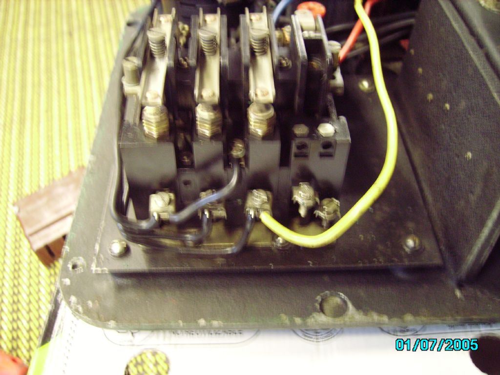
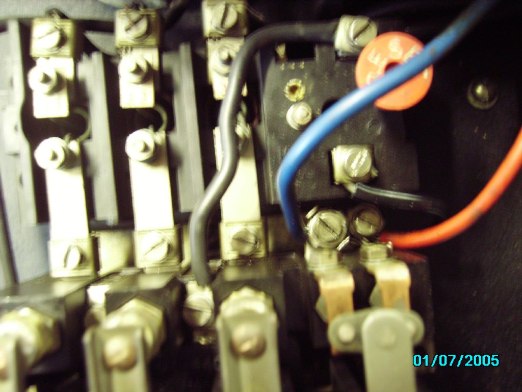
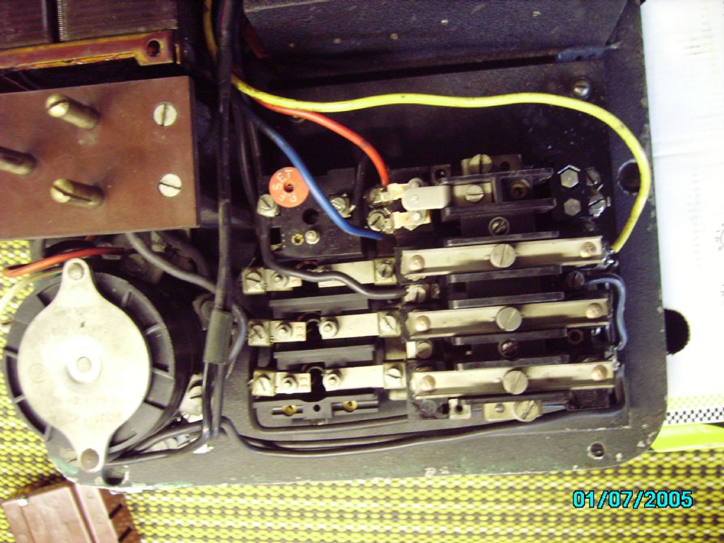
So, from Phils lathes wiring, I understand I need the three blue cables coming from the switch to go into the L1 L2 and L3 at the top of the contactor. The yellow needs to go into the top of the contactor, then the red and blue somewhere else? Which ones do they need to go in? Also, which ones do the cables to the motor go in. Do they go into the lowest 3 at the bottom, or the other 4 on the relay? Looks like we're on lockdown now, So I may as well get it all done! Thanks
Edited By Richard Kirkman 1 on 23/03/2020 21:18:53 |
| Phil Whitley | 24/03/2020 13:19:41 |
1533 forum posts 147 photos | Hi Richard, very neat work in the motor plate, I have done this job many times, and how easy it is is in direct proportion to how heavy the motor is, and how well you can get in to the job! It is NEVER easy! The three blue wires from the rotary switch go to L1 L2 and L3 on the top of the contactor. 13 NO (normally open) and 14 NO are the holding in contacts which operate the no volt release. the three wires to the motor connect to the A b and C connections on the overload. Did you get a wiring diagram with the contactor? if so, can you scan it and email or post up a copy and I can do a diagram for you. Phil. |
| Richard Kirkman 1 | 24/03/2020 13:31:18 |
| 334 forum posts 799 photos | Thanks, Phil, It really would have been a nightmare if I hadn't taken the motor plate out of the lathe! The jigsaw made it so much quicker, I would have been there a lot longer chain drilling and filing otherwise I'll fit the blue and black wires then I'll get some more pictures for you. It didn't come with a diagram but there was a diagram on the side of the contactor so I'll get a picture of that for you Then I'll start draining the lathe so I can work on the gaskets. I'll take lots of pictures so you'll know exactly what to do when you replace your bearings! (Not that it's particularly difficult) Thanks |
| Phil Whitley | 24/03/2020 14:18:26 |
1533 forum posts 147 photos | Have you linked the blue wire to the terminal above in the limit switch! See the diagram I did for you.
Phil
|
| Richard Kirkman 1 | 24/03/2020 14:24:36 |
| 334 forum posts 799 photos | The blue yellow and red are all connected to the limit switch in the same locations as your lathe from the pictures you sent at the bottom of page 2 on this thread
|
| Phil Whitley | 24/03/2020 14:42:04 |
1533 forum posts 147 photos | Yes, that is correct, but you also need a link wire from the blue wire terminal to the spare terminal on the switch, which is not visible in the pic. I have checked the wiring diagram, and it does show it. but it is not obvious on the pics. Look on the diagram in your manual. Phil Edited By Phil Whitley on 24/03/2020 14:44:39 |


Please login to post a reply.
Magazine Locator
Want the latest issue of Model Engineer or Model Engineers' Workshop? Use our magazine locator links to find your nearest stockist!
Sign up to our Newsletter
Sign up to our newsletter and get a free digital issue.
You can unsubscribe at anytime. View our privacy policy at www.mortons.co.uk/privacy
Latest Forum Posts
- hemingway ball turner
04/07/2025 14:40:26 - *Oct 2023: FORUM MIGRATION TIMELINE*
05/10/2023 07:57:11 - Making ER11 collet chuck
05/10/2023 07:56:24 - What did you do today? 2023
05/10/2023 07:25:01 - Orrery
05/10/2023 06:00:41 - Wera hand-tools
05/10/2023 05:47:07 - New member
05/10/2023 04:40:11 - Problems with external pot on at1 vfd
05/10/2023 00:06:32 - Drain plug
04/10/2023 23:36:17 - digi phase converter for 10 machines.....
04/10/2023 23:13:48 - More Latest Posts...
- View All Topics
Support Our Partners


Shopping Partners
Subscription Offer

Latest "For Sale" Ads
- Reeves** - Rebuilt Royal Scot by Martin Evans
by John Broughton
£300.00 - BRITANNIA 5" GAUGE James Perrier
by Jon Seabright 1
£2,500.00 - Drill Grinder - for restoration
by Nigel Graham 2
£0.00 - WARCO WM18 MILLING MACHINE
by Alex Chudley
£1,200.00 - MYFORD SUPER 7 LATHE
by Alex Chudley
£2,000.00 - More "For Sale" Ads...
Latest "Wanted" Ads
- D1-3 backplate
by Michael Horley
Price Not Specified - fixed steady for a Colchester bantam mark1 800
by George Jervis
Price Not Specified - lbsc pansy
by JACK SIDEBOTHAM
Price Not Specified - Pratt Burnerd multifit chuck key.
by Tim Riome
Price Not Specified - BANDSAW BLADE WELDER
by HUGH
Price Not Specified - More "Wanted" Ads...
Get In Touch!
Do you want to contact the Model Engineer and Model Engineers' Workshop team?
You can contact us by phone, mail or email about the magazines including becoming a contributor, submitting reader's letters or making queries about articles. You can also get in touch about this website, advertising or other general issues.
Click THIS LINK for full contact details.
For subscription issues please see THIS LINK.
Digital Back Issues


Donate

 Register
 Log-in
Model Engineer Magazine
- Percival Marshall
- M.E. History
- LittleLEC
- M.E. Clock

ME Workshop
- An Adcock
- & Shipley
- Horizontal
- Mill

Subscribe Now
- Great savings
- Delivered to your door

Pre-order your copy!
- Delivered to your doorstep!
- Free UK delivery!
All Forum Topics > Help and Assistance! (Offered or Wanted) > Colchester Student Mk1 Won't Start