Forum sponsored by:

Warco GH600
| Dan_B | 10/03/2020 10:33:41 | ||
| 24 forum posts 16 photos | Hi, I have read through this discussion and found it very helpful to read about your experiences with the GH600 as i'm am seriously considering placing an order. Could you please confirm if the machine is capable of screw cutting left hand threads? Thanks Dan | ||
| Jed Martens | 10/03/2020 15:43:32 | ||
 85 forum posts 54 photos | I've never tried it (still trying to get the hang of right hand threads), but you can reverse the lead-screw direction relative to the spindel - ie: have the cutter move left to right when you engage the the half-nut. Does that result in a left-hand thread? | ||
| Lee Kennedy | 10/03/2020 21:41:56 | ||
| 17 forum posts 5 photos | Thanks for this thread, interesting stuff. My GH600 was delivered early January but it’s still on the pallet due to my workload at the moment. i do plan on stripping the machine and cleaning up all rough edges. Also thanks to Jed who very kindly allowed me to visit him and see the GH600 first hand before I placed my order.
lee | ||
| Dan_B | 18/03/2020 09:11:50 | ||
| 24 forum posts 16 photos | Hi, Thanks for confirmation on the screw cutting. I have now ordered my GH600, really looking forward to it’s arrival. I am planning my tools and it would be really useful to know the spindle thread size, any current owners know of hand what it is? thanks
Dan | ||
| Howard Lewis | 18/03/2020 09:57:31 | ||
| 7227 forum posts 21 photos | Would be surprised if the spindle thread (Assuming a screw on chuck ) were anything other than Right Hand. A Left Hand thread would encourage the chuck to unscrew when cutting! Warco spec says that the Chuck mounting is Flange. So no Mandrel thread. Chucks are probably retained to flange by three or four studs and nuts. Posibly M8? GH600 owners can confirm these details Howard | ||
| Grindstone Cowboy | 18/03/2020 11:02:22 | ||
| 1160 forum posts 73 photos | I suspect Daniel was caught out by his auto-correct, and was meaning to say "any current owners know off-hand what it is?" regarding the spindle thread size. Unfortunately I have no idea, but someone might. | ||
| not done it yet | 18/03/2020 11:44:07 | ||
| 7517 forum posts 20 photos | I would not be placing an order unless I had studied the specification thoroughly beforehand. I’m not, but I did look and - as Howard posted - it clearly states:
I never use ‘auto-correct’.🙂 | ||
| Dan_B | 18/03/2020 12:56:21 | ||
| 24 forum posts 16 photos | Thanks for clarifying. My previous experience was with a Myford 7. I hadn't really given the chuck mounting much thought as the Warco machine is supplied with 3 and 4 jaw chucks. I had just started thinking today about my current collet setup and if i could adapt with a new back plate for the Warco. Regards Dan | ||
| Howard Lewis | 18/03/2020 13:04:39 | ||
| 7227 forum posts 21 photos | Hopefully, if your present collet set up is 2MT, (being ex Myford 7 Series ) you won't need a backplate. All that will be needed will be a 4 MT to 2 MT reducer. They are available. Chance are that a 4MT - 3MT sleeve will come with the lathe, but you need to look for a 4MT - 2MT. Take a look at: Arc Euro (They offer both Open Ended, and Tang versions ) Chronos , RDG or Warco themselves And there will probably be other UK suppliers. Howard | ||
| Dan_B | 18/03/2020 13:07:40 | ||
| 24 forum posts 16 photos | My current set was mounted on a Myford backplate so not quite that simple. I cant remember what size i choose now, need to get in the workshop and have a look. I'm sure i can sort something out though or I may decide to sell the collet set with the Myford. Dan | ||
| Jed Martens | 18/03/2020 13:39:04 | ||
85 forum posts 54 photos | As Howard says, the chucks bolt onto the flange of the spindle, there is no thread. There are holes for both 3 and 4 bolt patterns. For some reason the 4 jaw chuck was supplied with a back-plate, but the chuck will bolt directly to the flange, so I ditched the back-plate. I use ER32 collets, and purchased a collect chuck from ARC. Again, this bolts directly to the spindle flange. So I haven't had to use back-plates at all. The internal taper of the spindle is 4MT, but aside from a dead centre (supplied with the lathe) I haven't made use of this. Jed | ||
| not done it yet | 18/03/2020 13:39:23 | ||
| 7517 forum posts 20 photos | Sell only the myford back plate with the lathe? Make a new back plate to fit the ER collet chuck to your new lathe? If you were very lucky, the chuck might even bolt up directly to the flange.... but I would (always) make a plate to accurately fit the chuck spigot (and flange spigot, if it has one) and face it in situ to be sure of it running true. You are likely to benefit from having an ER system for the new lathe and selling, just to buy again, is not exactly sensible In my book - unless you intend to up-grade on quality. | ||
| Triumphboy | 01/04/2020 16:14:40 | ||
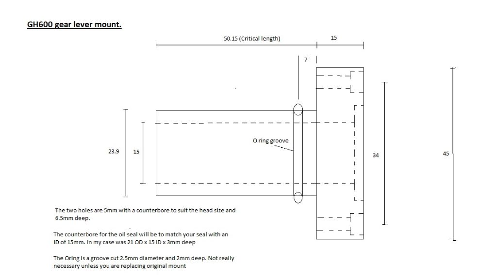
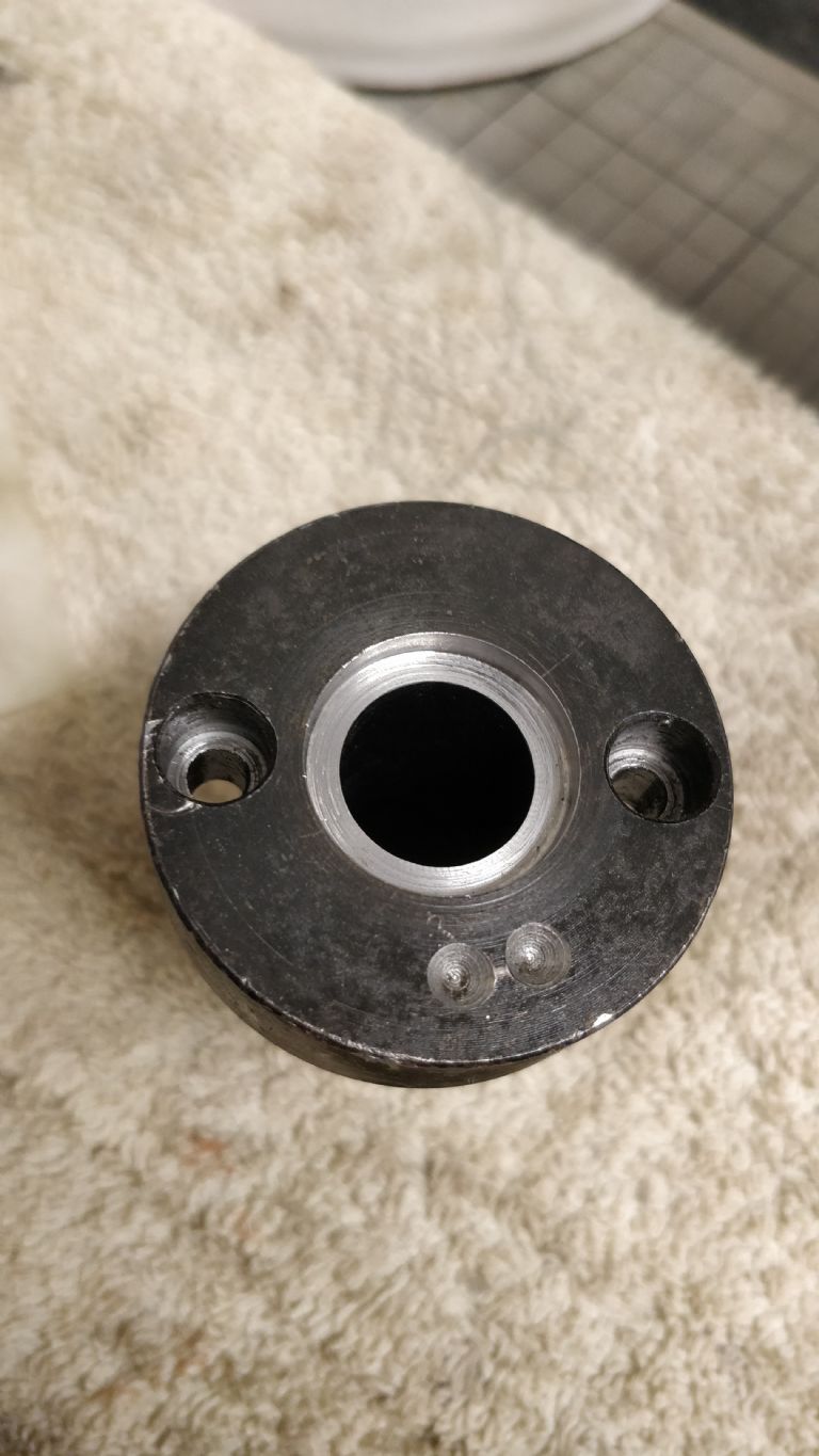
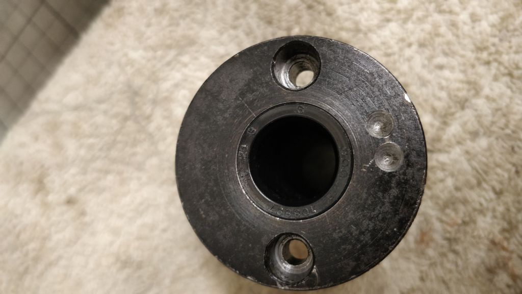
 23 forum posts 4 photos | GH600 Lathe Oil Leak Repair
After my previous rambles about oil leaks, I finally completed the detection, thought process and solution for this, the largest of the leaks. I have produced a PDF document explaining the process I used to sort out this oil leak. I tried to attach it here but I couldn't figure out if you could or couldn't add attachments. If anyone is interested, I can email it to you and if you decide you want to go ahead, I can post the replacement lever mount that needs fitting to allow you to modify your unit, as a loan unit while you machine yours. All of this took many hours and became a project that I / we shouldn't have to do but there you go! Hopefully, these steps will provide help to someone that identifies the same issue on their machine. The O ring prevents a bit of the leakage but most of the oil was coming out of the lever hence the oil seal. All the dimensions are in the PDF. Note:- The O ring is a 2.5mm cross section 19mm ID (Slightly stretched) and the front Oil seal is 21mm OD x 15mm ID x 3mm thick.
Best regards and good luck. Triumphboy. J Edited By Triumphboy on 01/04/2020 16:18:34 Edited By Triumphboy on 01/04/2020 16:32:09 | ||
| Triumphboy | 01/04/2020 16:16:17 | ||
23 forum posts 4 photos |
Edited By Triumphboy on 01/04/2020 16:31:02 | ||
| Triumphboy | 01/04/2020 16:41:11 | ||
23 forum posts 4 photos |
| ||
| Triumphboy | 01/04/2020 16:41:47 | ||
23 forum posts 4 photos |
| ||
| Triumphboy | 01/04/2020 16:42:10 | ||
23 forum posts 4 photos |
| ||
| IRT | 03/06/2020 22:26:30 | ||
| 151 forum posts 44 photos | Has anyone modified their GH600 to lock the cross-slide yet?
| ||
| Dan_B | 05/06/2020 17:04:29 | ||
| 24 forum posts 16 photos | I have been looking through Grizzly lathe manuals seeking better instructions than the Warco manual and came across a cross slide lock screw on a similar looking setup. It is the usual format of gib strip lock screw.
I have had my GH600 two months now and still have a few teething issues to get through as i haven't had much time to fiddle yet. One problem i have is with surface finish. So far i haven't managed to eliminate the rough finish shown here (its worse than it looks when you run your nail over it and feels like a fine thread):
I have made the following checks:
I'm using an insert tool with a fresh edge, it is a TPMR 110304. I have reset all of the gib strip, i would say that i have the top slide too tight, the cross slide perfect and maybe an issue with the saddle. I have set the gib strip at the rear of the saddle and snugged it up quite a bit from the factory setting. I tested with a DTI on the top of the saddle to see if there was any lift and measured 0.01mm. Should i attempt to tighten this gib further? If i move the DTI and test the saddle at the front i can measure 0.025mm of lift but don't see anyway to adjust this? Here is a diagram, it would be parts 45 and 46 that would need to be adjusted. Is this normal?
My other thought was spindle preload so with a DTI on the top of the register flange and a large drill for leverage I measured 0.01mm of lift. I could equally measure a further 0.01mm in the downwards direction from neutral so i'm not sure if it is deflection rather than bearing clearance. Again does this sound OK or is the movement excessive? I didn't expect any movement so close to the bearing. Any advice on what to try next or where I'm going wrong would be appreciated. Incidentally parting off has been a terrible experience so far and i suspect connected to the surface finish issue. Kind regards Dan | ||
| Martin Connelly | 05/06/2020 17:57:32 | ||
 2549 forum posts 235 photos | Feed rate seems very low. Using an insert you need to make it work and not rub. Try a feed of 0.125mm/rev. For small cuts the depth of cut should be similar to or below the radius of the insert but not too small. These inserts have 0.4mm radius so try 0.2mm DOC. Tools should be on centre height. RPM depends on the diameter of the stock. If the diameter of the stock is 10mm then try 1500 RPM if that is the fastest your lathe goes. Bigger diameter reduce RPM eg 20mm (double 10mm) half the RPM. There is a thread that is accessed from the home page under workshop/processes I think regarding speeds and feeds. Martin C Link added Edited By Martin Connelly on 05/06/2020 17:59:22 |


Please login to post a reply.
Magazine Locator
Want the latest issue of Model Engineer or Model Engineers' Workshop? Use our magazine locator links to find your nearest stockist!
Sign up to our Newsletter
Sign up to our newsletter and get a free digital issue.
You can unsubscribe at anytime. View our privacy policy at www.mortons.co.uk/privacy
Latest Forum Posts
- *Oct 2023: FORUM MIGRATION TIMELINE*
05/10/2023 07:57:11 - Making ER11 collet chuck
05/10/2023 07:56:24 - What did you do today? 2023
05/10/2023 07:25:01 - Orrery
05/10/2023 06:00:41 - Wera hand-tools
05/10/2023 05:47:07 - New member
05/10/2023 04:40:11 - Problems with external pot on at1 vfd
05/10/2023 00:06:32 - Drain plug
04/10/2023 23:36:17 - digi phase converter for 10 machines.....
04/10/2023 23:13:48 - Winter Storage Of Locomotives
04/10/2023 21:02:11 - More Latest Posts...
- View All Topics
Support Our Partners


Shopping Partners
Subscription Offer

Latest "For Sale" Ads
- Reeves** - Rebuilt Royal Scot by Martin Evans
by John Broughton
£300.00 - BRITANNIA 5" GAUGE James Perrier
by Jon Seabright 1
£2,500.00 - Drill Grinder - for restoration
by Nigel Graham 2
£0.00 - WARCO WM18 MILLING MACHINE
by Alex Chudley
£1,200.00 - MYFORD SUPER 7 LATHE
by Alex Chudley
£2,000.00 - More "For Sale" Ads...
Latest "Wanted" Ads
- D1-3 backplate
by Michael Horley
Price Not Specified - fixed steady for a Colchester bantam mark1 800
by George Jervis
Price Not Specified - lbsc pansy
by JACK SIDEBOTHAM
Price Not Specified - Pratt Burnerd multifit chuck key.
by Tim Riome
Price Not Specified - BANDSAW BLADE WELDER
by HUGH
Price Not Specified - More "Wanted" Ads...
Get In Touch!
Do you want to contact the Model Engineer and Model Engineers' Workshop team?
You can contact us by phone, mail or email about the magazines including becoming a contributor, submitting reader's letters or making queries about articles. You can also get in touch about this website, advertising or other general issues.
Click THIS LINK for full contact details.
For subscription issues please see THIS LINK.
Digital Back Issues


Donate

 Register
 Log-in
Model Engineer Magazine
- Percival Marshall
- M.E. History
- LittleLEC
- M.E. Clock

ME Workshop
- An Adcock
- & Shipley
- Horizontal
- Mill

Subscribe Now
- Great savings
- Delivered to your door

Pre-order your copy!
- Delivered to your doorstep!
- Free UK delivery!
All Forum Topics > Manual machine tools > Warco GH600