Forum sponsored by:

Stringer EW lathe
Looking for information - advice etc.
| V8Eng | 23/12/2012 20:42:28 |
| 1826 forum posts 1 photos |
All you EW fans. Here is an advert from 11th June 1953 issue of ME, hope it makes interesting reading.
|
| V8Eng | 24/12/2012 18:39:18 |
| 1826 forum posts 1 photos | Sorry about the missing image in my previous post, hopefully I got it right this time!
Edited By V8Eng on 24/12/2012 18:44:56 |
| Stub Mandrel | 31/12/2012 22:20:55 |
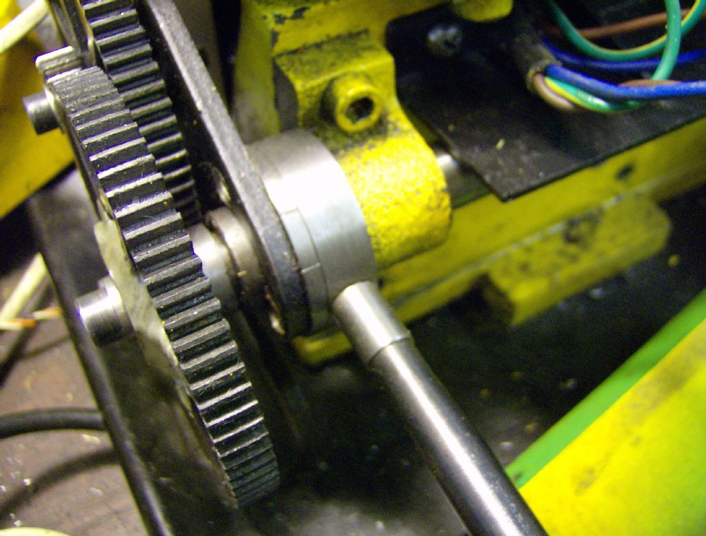
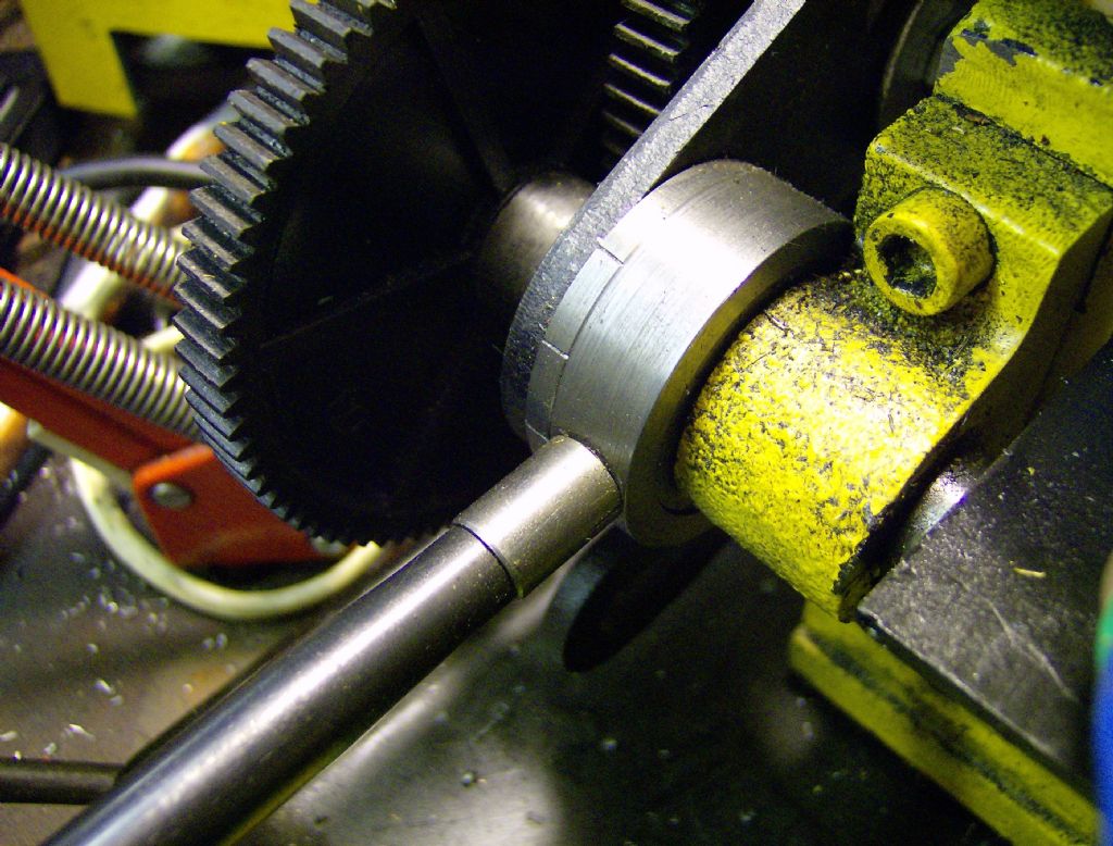
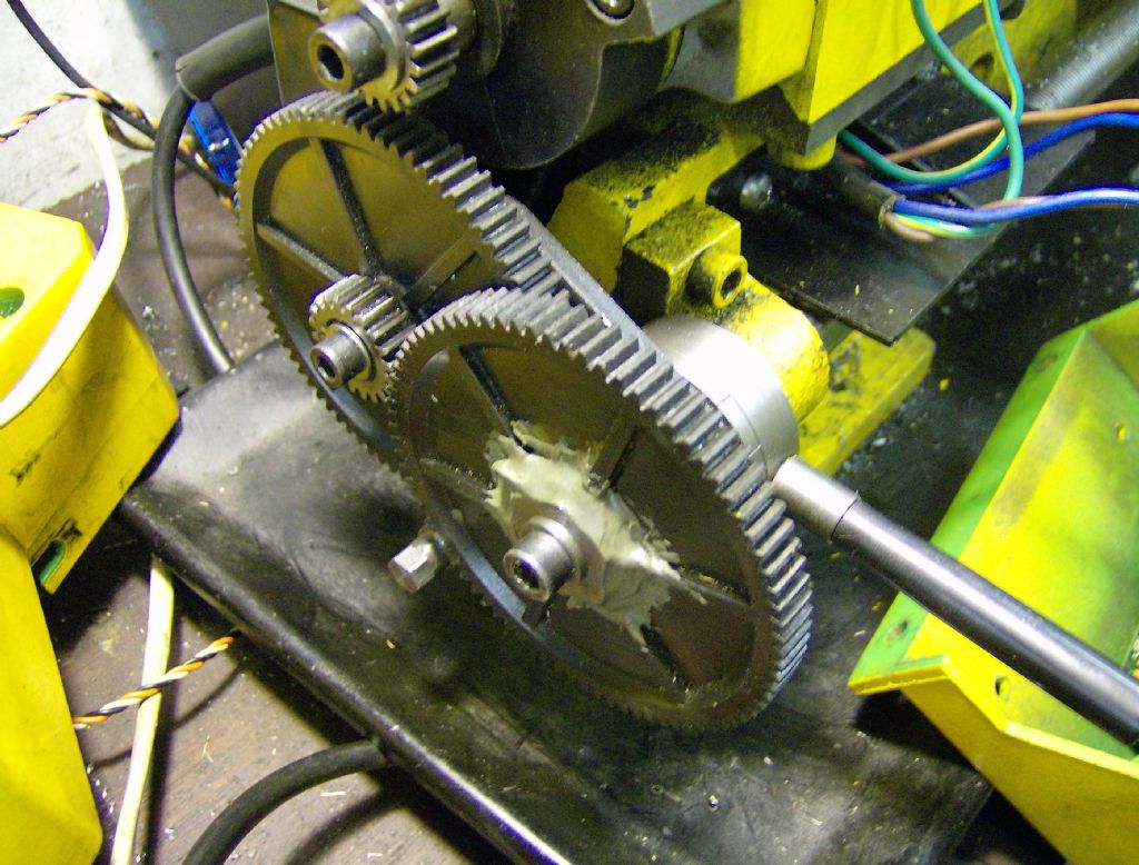
 4318 forum posts 291 photos 1 articles | As the Chilean red suffuses into my veins this New Year's eve I am tempted to contribute on a subject beyond my competence. What happened? the words have gone all lopsided? I made a leadscrew clutch for my mini lathe - irelevant? Perhaps? But I did it by a very simple expedient - the banjo in this case has an arctuate (good eh?) slot which permits it to be adjusted for different gears. I added a bellevile washer and an extended nut so that it can be set so the gear can be moved in or out of mesh and stay that way. I also added a simple arrangement so that a lever (which protrudes through a slot in the gearbox) can move the gears in and out of mesh, just by moving the banjo. A cunning (i.e. too complicated to describe in a state of partial; inebriation) arrangement means the lever can adopt one of three different positions to allow for different gear sizes. Result? A simple clutch that works for both fine feed and gear cutting BUT it does not keep the gear engagement like Gray's masterpieces as you can engage the gears at any relative position. That said it does make it very easy to securely engage or disengage the gear train without any spanner wangling and probably could apply to any banjo-style gearbox. Neil. |
| Stub Mandrel | 01/01/2013 19:19:35 |
4318 forum posts 291 photos 1 articles | To my surprise there are a few pics in my albums: The lver just pivots the banjo up and down on the end of the leadscrew bush. You may just make out two of three countersunk screws that hold the device to the banjo.
The lines on the left hand part show positions where the handle can be screwed in to an outer ring and engage with the inner 'hat' shaped part.
You can see the tiny extended nut that adjusts the grip poking out below the change wheels.
The body filler is just to stop a bush made from hex material rotating in the bore. A kindly chap sent me some surplus plastic chnge wheels when he converted to metal ones so I have a proper one their now. Neil |
| Stub Mandrel | 01/01/2013 22:04:28 |
4318 forum posts 291 photos 1 articles | At the very least it provides a way of stopping the leadscrew reliably without having to use a spanner or reach round the back to play with the tumbler reverse. It really is no different from putting the tumbler in neutral, but it is so much quicker and easier. It also speeds up changing the gear train a little. I keep meaning to make a super-fine feed banjo with another 80:20 gear pair, to get ~1 thou per revolution. Neil |
| Andyf | 01/01/2013 23:59:23 |
| 392 forum posts | I'm a bit late on parade here, and may be missing something, but am a little surprised by Alan's comment that "I`m all in favour of not cutting the lead screw to achieve the clutch design." A dog clutch on the leadscrew has been in use on the similarly sized Cowells lathe for 40 years or so, and my Perris (which became the Cowells) has the same arrangement. It uses the heads of small Allen screws (described in Mr Perris's build instructions as "specially prepared" and about 4BA, I think) engaged in slots in a sliding bobbin to transmit the drive, a task which they have been successfully accomplishing on my lathe for going on half a century. The first section of a two-part article by Tony Jeffree appears in MEW No. 198, describing fitting a dog clutch to his Cowells. It looks as though it might work on the EW too, if an additional plummer block is provided for the leadscrew. This is a long thread, and if I have missed some vital point, please just ignore this post. Andy |
| Andyf | 02/01/2013 13:17:42 |
| 392 forum posts | Yes, Alan, I see from your albums that, even if the bed casting were milled out to provide a seat for another leadscrew bearing block, there would be little room left between that block and the existing bearing at that end to accommodate not only the sliding bobbin for the clutch but also two collars to prevent axial movement of each part of the leadscrew. Andy PS Just to create a few more ripples in the pond, I see that the EW seems to have a solid leadscrew nut. So did my Perris, and moving the saddle any distance either by hand cranking or with the power feed was tedious because the pitch is 1mm (50 turns to shift the saddle two inches). The solid nut was bolted on under the front end of the saddle, so I replaced it with a little apron carrying a single half nut. No apron handwheel, but with the half nut disengaged the saddle can be pushed quite easily along the bed . I don't know why Cowells don't do the same; after all, they charge enough for their machines. |
| Andyf | 02/01/2013 15:23:05 |
| 392 forum posts | I quite understand your wish not to butcher a lathe which is in original consdition, Alan. I felt the same about my Perris until the headstock fractured, necessitating fairly major surgery. The half-nut was fitted using existing bolt holes, so drilling or suchlike, and I can always put the solid one back. But it was only added to reduce the twiddling on the 1mm pitch leadscrew; yours seems to be 8tpi, so movement will be three times quicker. Anyway, this thread is about EWs, not Perrises/Cowellses, so I'll shut up. Andy |
| Stub Mandrel | 10/01/2013 19:53:15 |
4318 forum posts 291 photos 1 articles | GI got up to go to work at five this morning! But I came back a bit early to be rewarded by the latest ME. In it is a picture of a version of Gray's screwcutting arrangement - modified so it can be disengaged by swivelling the banjo! Neil
|
| NJH | 11/01/2013 13:17:41 |
 2314 forum posts 139 photos | Alan Look on this site at the thread " Screwcuting Simplified" ( and gasp in amazement! ) regards
Norman |
| NJH | 11/01/2013 16:19:00 |
2314 forum posts 139 photos | Alan I was responding to your post of 10.35 this morning where you were inquiring about Gray's screwcutting modification. Yes the thread shows the version for the Myford S7 but he has also designed similar for other lathes.( I doubt that he will do so for the EW.) My gasps of admiration refer to the design and the quality of Gray's work which I'm sure you will appreciate when you get time to study that thread. Norman
Edited By NJH on 11/01/2013 16:20:23 |
| Stub Mandrel | 12/01/2013 15:39:06 |
4318 forum posts 291 photos 1 articles | Hi Alan, Sorry to be slow responding, Norman has pointed you in the right direction already. Neil |
| IanT | 24/01/2013 23:13:28 |
| 2147 forum posts 222 photos | I agree about the utility of being able to take the tailstock on and off easily Alan. Mine gets removed with great freequency and this is likely to happen even more as things progress. I have 'considered' this problem (but not got much further I'm afraid) and had decided that a larger dial and handle would be very useful (2"+) but that I would need to make it quickly removable - so some form of quick engage/disengage. I also find that I'm using the boring table more and more and I'm getting tired of changing between this and the normal topslide. So one of my high priority jobs will be to make a simple mounting to fit my economy QCTH to the boring table - as I don't often seem to need to taper turn. Of course this will require the larger leadscrew dial to enable putting on the cut (using the topslide at the moment generally) and will also bring forward a saddle stop I suspect. Still working on various things and one of them (boiler test pump) is progressing well. Photo is of EW Vertical slide mounted (via a simple adaptor plate) on the boring table. I'd just milled flats top and bottom on the ram yoke and I was about to cut the slot in the middle. Everything went well I'm pleased to report. The pump body is sat on the side of the boring table for reference.
Hope this finds everyone well. Regards,
IanT Edited By IanT on 24/01/2013 23:15:57 |
| Andyf | 25/01/2013 01:23:44 |
| 392 forum posts | Alan, if your leadscrew is fractional pitch like 8tpi, choosing the right gear ratio between the offset handle and the leadscrew would enable you to put 100 marks on the dial, each representing 1 thou, and one full turn of the dial reflecting 0.010" travel. Compared with 125 graduations, this would eliminate some mental arithmetic if you want to shift the saddle along by (say) 0.460". With the right ratio, four full dial turns plus another 60 thou. That's easier than than 3 x 0.125 = 0.375", which when subtracted from the desired 0.460" leaves 0.085, so 3 full dial turns plus another 0.085". Being a bit of a duffer at sums, I fitted a geared dial to my 12tpi leadscrew (a really awkward 0.8333" per turn) which has made life a lot easier, even though there's no idler and the dial contra-rotates. Andy |
| IanT | 25/01/2013 10:34:13 |
| 2147 forum posts 222 photos | I wonder whether such precision is really neccessary in practice Andy. A simple leadscrew dial with a diameter of 2" would provide a dial circumference of 6.28" - so I could divide it by 12.5 and still have 0.5"+ between major divisions (each division being 10 thou). The addittion of a saddle stop, possibly with the option to fit an adjustable micrometer head would probably be more than enough for most of my turning needs on the EW. Generally I think I'd prefer to have some idea of where I am - but leave the "precision" to something mechanical (especially when boring for instance). (Co-incidentally - a well-known online supplier sells a very nice little micrometer head for about £10 - I've just purchased one but not used it in anger yet). Is it so awkward to have 12 major 10' divisions and a 5' last division? It occurs to me to mention that for many years I tended to measure smaller distances in mm as I found fractional inch measurements much harder to manage (although a friend can add a long list of 'fractionals in his head - apparently converts it all to 64ths and then goes back). Personally, I used to always converted any smaller imperial measures into 'mm' for CAD drawings etc. However, I have now returned to Imperial and prefer to work in 'thous' (which is a decimal system). It is just as easy use as 'mm' and most of my equipment is quite old and they mostly have imperial dials. My tooling is a mix of metric & imperial tooling - but I have a simple printed list (courtesy Excel) of common metric & fractional sizes > thous that I use and I've quickly become used to working in this way. All my new CAD drawings will now be in decimal Imperial (Inches/Thous). May sound like a step back - but it seems to work well for me. I'm not trying to reignite this age old argumemnt by the way - just stating how my preferences have evolved. Regards, Ian T |
| Andyf | 25/01/2013 12:34:58 |
| 392 forum posts | I found it pretty essential when all I had for miling operations was a vertical slide, Ian. The dial on the topslide would cope perfectly well with most turning down or facing operations which require a degree of precision. But, as my lathe is a small one, its topslide is usually set at an angle so it doesn't foul the tailstock, and I have got into the habit of using the leadscrew dial. Andy |
| IanT | 26/01/2013 17:28:11 |
| 2147 forum posts 222 photos | I've always wondered how Mr Stringer meant his customers to mount the Vertical Slide quite honestly Andy. I am certain that the V/S is original EW equipment but with a single hole - I can only assume that it was meant to go on top of the cross slide - not the most stable mounting and mine won't quite fit (I think the toolpost pillar on mine is slightly bent). It makes much more sense to mount it on the boring table (also EW O/E) but it clearly won't mount as made. So a simple adaptor plate was made and seems to work very well. As you will see the tailstock has been removed simply for ease - it would be possible to work without it but I perfer to get it out of the way.
I do quite like the idea of a geared leadscrew handle - but my work-rate it too low to add any more 'projects' to my list - life is too short (and getting shorter I'm afraid) and I would very much like to finish some of my other projects! The odd steam engine for instance! Regards,
Ian T |
| Andyf | 27/01/2013 13:57:31 |
| 392 forum posts | Ian, I have a very similar vertical slide for my Perris lathe (still produced as the Cowells). Fixing is by a single stud into one of the Tee slots on the cross slide, a somewhat precarious arrangement. As to your dial, you mentiond that you could go up to 2" diameter. The one I made for my Iarger (but still small) lathe is about 2.05" diameter, and the 100 divisions are thus approximately 1/16" apart. Without stooping, they can be read easily using my varifocal specs. On a 2" dial, 125 marks would be about 1/20" apart, and should still be pretty readable. The fine downfeed on my Dore Westbury miller has 130 divisions on a 1.5" diameter dial, and those are getting a bit close together (and hard to see on the brass collar), though at least the dial is around neck height. Andy |
| IanT | 28/01/2013 10:45:06 |
| 2147 forum posts 222 photos | Michael, A quick ME Index check suggests that the Duplex articles you refer to might be part of their "In the Workshop" series. Volume 101 - Issues 2528, 2530 & 2532 may be the ones to look at I think. I'll see if I've got them this evening. Regards, Ian T |
| IanT | 29/01/2013 09:36:34 |
| 2147 forum posts 222 photos | I think i've found the relevant issue thanks Michael - No 2528 "In the Workshop" No 49 - A Saddle Traversing Gear & Fine Feed. The design basically uses an intermediate set of gears that are disengaded by means of a 'bobbin' activated by a lever. As some modification to the quadrant is required, Duplex suggested that it would probably be best to use a dedicated quadrant for the unit and swop between this and the standard one as required. Alan - if you would like to examine this design (for the ML7) I will scan it and send you a copy by PM. Regards,
IanT |


Please login to post a reply.
Magazine Locator
Want the latest issue of Model Engineer or Model Engineers' Workshop? Use our magazine locator links to find your nearest stockist!
Sign up to our Newsletter
Sign up to our newsletter and get a free digital issue.
You can unsubscribe at anytime. View our privacy policy at www.mortons.co.uk/privacy
Latest Forum Posts
- hemingway ball turner
04/07/2025 14:40:26 - *Oct 2023: FORUM MIGRATION TIMELINE*
05/10/2023 07:57:11 - Making ER11 collet chuck
05/10/2023 07:56:24 - What did you do today? 2023
05/10/2023 07:25:01 - Orrery
05/10/2023 06:00:41 - Wera hand-tools
05/10/2023 05:47:07 - New member
05/10/2023 04:40:11 - Problems with external pot on at1 vfd
05/10/2023 00:06:32 - Drain plug
04/10/2023 23:36:17 - digi phase converter for 10 machines.....
04/10/2023 23:13:48 - More Latest Posts...
- View All Topics
Support Our Partners


Shopping Partners
Subscription Offer

Latest "For Sale" Ads
- Reeves** - Rebuilt Royal Scot by Martin Evans
by John Broughton
£300.00 - BRITANNIA 5" GAUGE James Perrier
by Jon Seabright 1
£2,500.00 - Drill Grinder - for restoration
by Nigel Graham 2
£0.00 - WARCO WM18 MILLING MACHINE
by Alex Chudley
£1,200.00 - MYFORD SUPER 7 LATHE
by Alex Chudley
£2,000.00 - More "For Sale" Ads...
Latest "Wanted" Ads
- D1-3 backplate
by Michael Horley
Price Not Specified - fixed steady for a Colchester bantam mark1 800
by George Jervis
Price Not Specified - lbsc pansy
by JACK SIDEBOTHAM
Price Not Specified - Pratt Burnerd multifit chuck key.
by Tim Riome
Price Not Specified - BANDSAW BLADE WELDER
by HUGH
Price Not Specified - More "Wanted" Ads...
Get In Touch!
Do you want to contact the Model Engineer and Model Engineers' Workshop team?
You can contact us by phone, mail or email about the magazines including becoming a contributor, submitting reader's letters or making queries about articles. You can also get in touch about this website, advertising or other general issues.
Click THIS LINK for full contact details.
For subscription issues please see THIS LINK.
Digital Back Issues


Donate

 Register
 Log-in
Model Engineer Magazine
- Percival Marshall
- M.E. History
- LittleLEC
- M.E. Clock

ME Workshop
- An Adcock
- & Shipley
- Horizontal
- Mill

Subscribe Now
- Great savings
- Delivered to your door

Pre-order your copy!
- Delivered to your doorstep!
- Free UK delivery!
All Forum Topics > General Questions > Stringer EW lathe