Forum sponsored by:

Stuart Twin Victoria (Princess Royal) Mill Engine
| JasonB | 12/03/2021 19:32:07 |
 25215 forum posts 3105 photos 1 articles | They don't do the heavy one now which just has a rectangular section rim, yours is a "T" shape with the six bosses. The lugs want removing from both the outer faces anyway, so on one side you would just need to turn a crisper recess and then make a separate barring ring that could be JBWelded into place. If you do it right that will cover the screw heads and as it will be painted could be made from anything easy to cut or what about a 3D print?
I did something similar on this engine where the barring holes were central so made it up from 3 water jet cut parts. Worth looking through it all as it covers a fabricated beam engine.
|
| Dr_GMJN | 12/03/2021 20:01:07 |
 1602 forum posts | That fabricated flywheel looks great. I was wanting to try cutting the notches myself, possibly using a gear wheel because I don’t have a rotary table. I could get an aluminium or mild steel ring laser-cut, JB weld it into the machined recess, and paint the whole lot. Then machine the notches out of the aluminium? I wanted to leave the notches bright. |
| JasonB | 12/03/2021 20:04:03 |
25215 forum posts 3105 photos 1 articles | In that case do it in steel |
| Dr_GMJN | 12/03/2021 23:00:02 |
1602 forum posts | I suppose aluminium would look a bit bright. |
| Dominic Bramley | 13/03/2021 12:24:24 |
| 60 forum posts 1 photos | Following this thread with interest as I have the Twin Vic kit and plan to make the Princess Royal with it at some point. I had not appreciated that the modern flywheels would cause a problem with the barring rack and no doubt would have come-a-cropper when I got to that point. Doc - I have no idea as to how laser cutting services price their jobs - but if there is any significant economy in getting multiples cut - then I'd be happy to go halves with you on a pair when it comes to getting the ring cut. Cheers Dom |
| Dr_GMJN | 22/03/2021 13:18:29 |
1602 forum posts | Posted by Dominic Bramley on 13/03/2021 12:24:24:
Following this thread with interest as I have the Twin Vic kit and plan to make the Princess Royal with it at some point. I had not appreciated that the modern flywheels would cause a problem with the barring rack and no doubt would have come-a-cropper when I got to that point. Doc - I have no idea as to how laser cutting services price their jobs - but if there is any significant economy in getting multiples cut - then I'd be happy to go halves with you on a pair when it comes to getting the ring cut. Cheers Dom Dom, yes I’ll let you know. |
| Dr_GMJN | 22/03/2021 13:22:26 |
1602 forum posts | About the only thing I’m fit for today, after the sledgehammer side effects of the Covid jab, is reading, so I’m going through the P.R. article again. Re the flywheel, it says “Machine the face and the boss, line and line across..” What does that mean? Thanks. |
| Dr_GMJN | 27/03/2021 22:22:23 |
1602 forum posts | Still puzzling over the connecting rods. It says to machine the rods down to 0.3” between the lines that mark the extents of the radiused transitions. Then switch to a tool with a 5/32” true radius, to form the transition radius as the middle diameter is reduced. But if you’ve just reduced the diameter between the extents with a step, how will the radiussed tool get rid of the step? You appear to be trying to form an internal radius where you’ve just put a corner, ie you need to add material. |
| JasonB | 28/03/2021 07:00:41 |
25215 forum posts 3105 photos 1 articles | Posted by Dr_GMJN on 27/03/2021 22:22:23:
It says to machine the rods down to 0.3” between the lines that mark the extents of the radiused transitions. The "lines are where the radius meets the taper so you are first turning to where the radiu starts and the second tool will then traverse further to the extent of the radius.
I'll have a look at the other bit. J PS I was like that on Friday after having mine on Thursday with what felt like the Flu. Edited By JasonB on 28/03/2021 07:53:15 |
| JasonB | 28/03/2021 07:43:02 |
25215 forum posts 3105 photos 1 articles | Line & line across looks like he just means face the hub back to the same plane that the side of the rim cleaned up to |
| Dr_GMJN | 28/03/2021 12:29:00 |
1602 forum posts | Posted by JasonB on 28/03/2021 07:00:41:
Posted by Dr_GMJN on 27/03/2021 22:22:23:
It says to machine the rods down to 0.3” between the lines that mark the extents of the radiused transitions. The "lines are where the radius meets the taper so you are first turning to where the radiu starts and the second tool will then traverse further to the extent of the radius.
I'll have a look at the other bit. J PS I was like that on Friday after having mine on Thursday with what felt like the Flu. Edited By JasonB on 28/03/2021 07:53:15 Thanks Jason, that would make more sense, but it’s not what it says in the instructions. The dimensions in the drawing are to the edge of the radius on the rectangular bits, not the circular section rod. Those same dimensions are also in the text, where it says to initially machine down between them. If you follow the written instructions, I think the radius would crash into the first set of bolt holes for the strap. It also says to mark the extents of the initial thinning with a felt-tip, but then once machined, to use a rule to find the extents of the rad. In that case why would you need a rule? It’s the same dimensions (there are no others), and you’ve just made a machined step to them, so it’s obvious where it is? There’s some error somewhere because you can’t use the same dimensions for both operations and end up with a smooth transition. I think what he meant was to add on the tip radius to the distance from the ends (ie he shouldn’t have quoted the drawing values for that initial operation) and as you say machine initially to that. Then mark with a felt tip and extend as necessary. Why you’d need a felt tip for one job and a rule for the other is also confusing to me - surely you’d just mark the initial length, and the final length and work to those? For me, the instructions are almost too detailed in this case because they seem to suggest different marking techniques for the same simple job. May well have misunderstood something, and I want to make sure I’m not scrapping a part because of this.
|
| JasonB | 28/03/2021 18:22:19 |
25215 forum posts 3105 photos 1 articles | Yes there is something wrong with how it's written. I would put a sharpie mark where I have put the pink lines on that image as they are easy to see while you rough out without the need to keep stopping and take measurements or have to scribe a deep line across the finished face of the ends. This will knock all the corners off and get you down to a round section. Now that you have roughed out change tool and cut the tapers forming the fillets at the same time either measuring or setting a stop, usually a bit of both is needed as the curve of the tool will extend further along the deeper it gets into the work. |
| Dr_GMJN | 28/03/2021 19:26:38 |
1602 forum posts | Posted by JasonB on 28/03/2021 18:22:19:
Yes there is something wrong with how it's written. I would put a sharpie mark where I have put the pink lines on that image as they are easy to see while you rough out without the need to keep stopping and take measurements or have to scribe a deep line across the finished face of the ends. This will knock all the corners off and get you down to a round section. Now that you have roughed out change tool and cut the tapers forming the fillets at the same time either measuring or setting a stop, usually a bit of both is needed as the curve of the tool will extend further along the deeper it gets into the work. Yep, that all makes sense. When I’m grinding the radiussed tool (planning on doing it on the linisher), are you supposed to harden it afterwards? Maybe dunk in water after grinding or something? Is there a special file for sharpening tools, or is it a case of re-grinding when the cut isn’t as good? New to all this - Thanks. |
| JasonB | 28/03/2021 19:45:29 |
25215 forum posts 3105 photos 1 articles | If you are grinding an HSS blank then it can be used as is. If grinding from gauge plate/silver steel then it will need hardening. Tough up with a slip stone or more likely these days a small diamond lap if the edge goes off, this can be used on both materials |
| Dr_GMJN | 29/03/2021 09:09:39 |
1602 forum posts | Posted by JasonB on 28/03/2021 19:45:29:
If you are grinding an HSS blank then it can be used as is. If grinding from gauge plate/silver steel then it will need hardening. Tough up with a slip stone or more likely these days a small diamond lap if the edge goes off, this can be used on both materials Ok Thanks. |
| Dr_GMJN | 30/03/2021 22:27:27 |
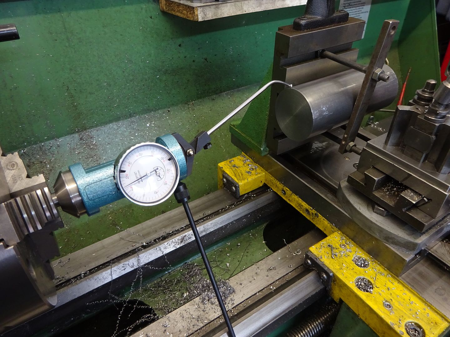
1602 forum posts | Posted by JasonB on 08/03/2021 13:29:38:
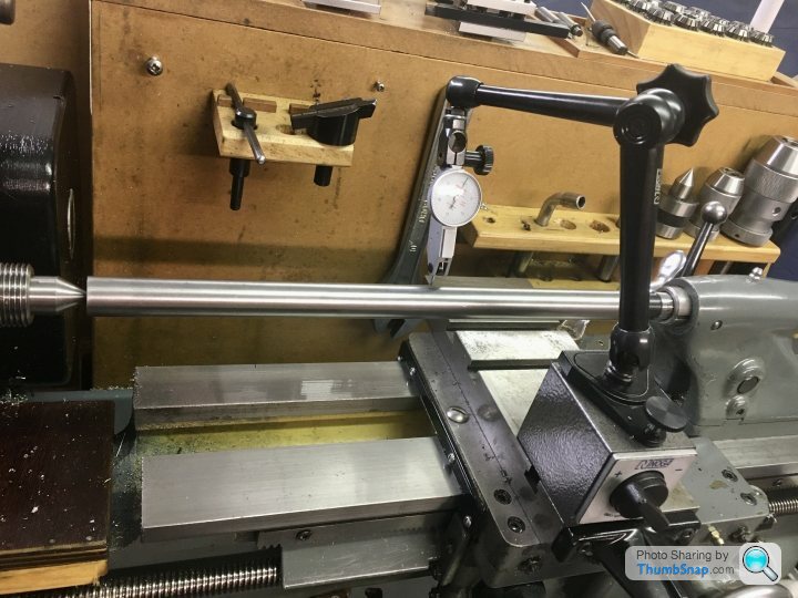
Clamp to cross slide with packing or to the Vertical slide of you have one. Flycut the end. Put DTI in lathe chuck and adjust bar's position until dti shows it's true and ctr drill with drill in spindle. I have used the wooden block method Ramon mentions in the past when I did not have a fixed steady for the Emco Strictly speaking the holes do not need to be spot on but it's handy for measuring tool projection though that can be got around by turning down a section around the toolbit hole to a known diameter Is a 1" bar going to be of use on your cylinders as it won't fit!. 3/4" would allow it to pass through the core (I think) and allow room for a few cuts & swarf
Edited By JasonB on 08/03/2021 13:31:20 I made a start on the boring bar, by drilling the centres. I used the vertical slide method, although it was quite tricky. I put the bar in the 3-jaw chuck, and then offered the vertical slide up, making sure the bar seated in one of the slots. Once everything was clamped up I checked the top surface and side with a dti, and it was quite a way off in terms of not being parallel with the bed. I couldn't really get it right to the dti, yet it slid in and out of the chuck quite freely. |
| Dr_GMJN | 04/04/2021 17:33:45 |
1602 forum posts | I’ve been looking at a couple of past threads on boring bars, and some seem to suggest a diagonal hole for the tool is better - presumably to increase stiffness. Before I cross-drill it (with an adjustment grub screw), is the diagonal method worth it? Is it a case of setting the bar at some angle in the vice and slot drilling to begin with? Thanks. |
| JasonB | 04/04/2021 18:30:16 |
25215 forum posts 3105 photos 1 articles | The angled designs tend to mount the tool at a specific angle so that a screw can be used to advance the tool by a set amount per turn. Never bothered myself and find the 90deg hole makes for easier tool grinding so all my homemade one sate 90deg, though the Micro bore head does have it's own scale so you know how much the tool is advanced but don't use that much. |
| Dr_GMJN | 05/04/2021 19:00:50 |
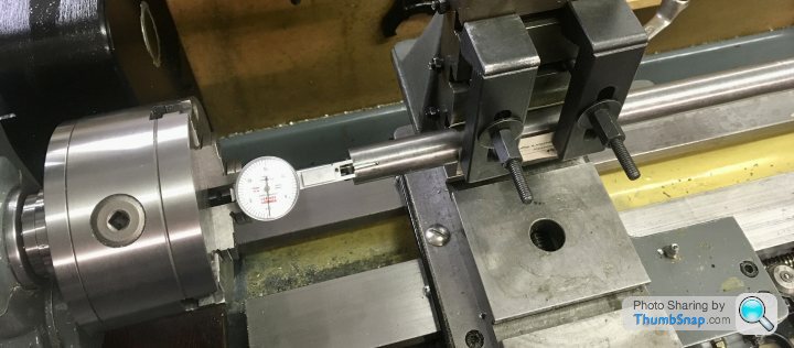
1602 forum posts | Posted by Ramon Wilson on 11/11/2020 08:40:15:
A simple pin set on centre line of the arc and another in the cylinder wall will locate the feet accurately enough while the JB sets, though I was underr the impression the mating area was going to be machined too. Yes another way this op can be done, but as Jason says it would be best to machine the lower surfaces after bonding - done with the cylinder held on a mandrel the dimension would be both identical over both parts and importantly parallel with the cylinder bore too You can make a simple 'tween centres boring bar of any size you want to suit the job. I have some made many years back from silver steel. They have a small flat on them where the cross hole for the 1/4 HSS cutter goes. By making the hole blind the flat area can be drilled and tapped for say a 6ba screw which helps move the cutter when very small movements are required. Remove screw, mic across flat and tool tip - simple maths gives the radius. There are other ways - inset adjustable carbide tips for instance but that above has served me well for a long time now - I much prefer to use 'between' centres for bores to eliminate taper. Soft solder will be sufficient!
Ramon This pic should help explain it better. The turned portion is to ensure the diameter is true to the axis of the centres. Radius required is dimension plus .462 across tool tip and flat
Edited By Ramon Wilson on 11/11/2020 08:52:42 I’m making the bar at the moment - what is the purpose of locally turning it true? I can see that it’ll give a co-axial cylinder where the tool is, but a I assumed you’d machine, measure and re-set the tool. I can’t figure out why you’d need a cylindrical portion of the bar? Also, I think I’ve cut the bar too long. Presumably it should be the minimum length for the job plus a bit - but how far each side should the ‘plus a bit’ be? Thanks. |
| JasonB | 05/04/2021 19:13:13 |
25215 forum posts 3105 photos 1 articles | As you will need to set the tool to desired radius plus half the bar diameter turning the area around the hole true ensured that the half diameter is actually half diameter not what half the bar is from the lathe axis. I think mine have a length approx equal to the bar dia turned true equalised about the hole Edited By JasonB on 05/04/2021 19:14:40 |


Please login to post a reply.
Magazine Locator
Want the latest issue of Model Engineer or Model Engineers' Workshop? Use our magazine locator links to find your nearest stockist!
Sign up to our Newsletter
Sign up to our newsletter and get a free digital issue.
You can unsubscribe at anytime. View our privacy policy at www.mortons.co.uk/privacy
Latest Forum Posts
- *Oct 2023: FORUM MIGRATION TIMELINE*
05/10/2023 07:57:11 - Making ER11 collet chuck
05/10/2023 07:56:24 - What did you do today? 2023
05/10/2023 07:25:01 - Orrery
05/10/2023 06:00:41 - Wera hand-tools
05/10/2023 05:47:07 - New member
05/10/2023 04:40:11 - Problems with external pot on at1 vfd
05/10/2023 00:06:32 - Drain plug
04/10/2023 23:36:17 - digi phase converter for 10 machines.....
04/10/2023 23:13:48 - Winter Storage Of Locomotives
04/10/2023 21:02:11 - More Latest Posts...
- View All Topics
Support Our Partners


Shopping Partners
Subscription Offer

Latest "For Sale" Ads
- Reeves** - Rebuilt Royal Scot by Martin Evans
by John Broughton
£300.00 - BRITANNIA 5" GAUGE James Perrier
by Jon Seabright 1
£2,500.00 - Drill Grinder - for restoration
by Nigel Graham 2
£0.00 - WARCO WM18 MILLING MACHINE
by Alex Chudley
£1,200.00 - MYFORD SUPER 7 LATHE
by Alex Chudley
£2,000.00 - More "For Sale" Ads...
Latest "Wanted" Ads
- D1-3 backplate
by Michael Horley
Price Not Specified - fixed steady for a Colchester bantam mark1 800
by George Jervis
Price Not Specified - lbsc pansy
by JACK SIDEBOTHAM
Price Not Specified - Pratt Burnerd multifit chuck key.
by Tim Riome
Price Not Specified - BANDSAW BLADE WELDER
by HUGH
Price Not Specified - More "Wanted" Ads...
Get In Touch!
Do you want to contact the Model Engineer and Model Engineers' Workshop team?
You can contact us by phone, mail or email about the magazines including becoming a contributor, submitting reader's letters or making queries about articles. You can also get in touch about this website, advertising or other general issues.
Click THIS LINK for full contact details.
For subscription issues please see THIS LINK.
Digital Back Issues


Donate

 Register
 Log-in
Model Engineer Magazine
- Percival Marshall
- M.E. History
- LittleLEC
- M.E. Clock

ME Workshop
- An Adcock
- & Shipley
- Horizontal
- Mill

Subscribe Now
- Great savings
- Delivered to your door

Pre-order your copy!
- Delivered to your doorstep!
- Free UK delivery!
All Forum Topics > Work In Progress and completed items > Stuart Twin Victoria (Princess Royal) Mill Engine