Forum sponsored by:

Stuart 10V Build Log - Complete Beginner...
| JasonB | 06/06/2020 07:03:58 |
 25215 forum posts 3105 photos 1 articles | That would be called a "spring pass" as it takes out any flex or spring in the tool without putting on any more cut.. You will find that the insert you are using is nor really sharp and would be better with a decent depth final cut so it will get pushed off more than a really sharp HSS tool or even a **GT insert, the interupted cut due to the slots in the side of your part won't help either. Depending on the job I will quite often do the last couple of passes with a HSS tool having taken the rest out with CCMT. in iron, bronze and brass I'm more likely to just use CCGT. |
| Dr_GMJN | 08/06/2020 16:05:50 |
 1602 forum posts | Thanks for that. I've come to a bit of a halt while I wait for some materials to make mandrels etc., and I'm going to add some power to my mill x-feed. I need some tooling too for the 10V - any advice on slitting saws for the conrod bearing and valve eccentric rod? Thanks. |
| Jon Cameron | 08/06/2020 16:44:31 |
| 368 forum posts 122 photos | Hi, The bearings could be cut with a hacksaw, then clamped in the mill vice to clean up the mating faces before soft soldering together for drilling and boring then again with a mandrel to turn the OD. I haven't the plans in front of me but if you are refering to the slot at the end of the conrod this can be done clamped in the milling vice and using a slot cutting milling bit to cut the slot. Drill the hole to bolt together first and gain correct distance, centre to centre then do the finish profiling. As you've found already it may be best to go slightly under size on the milling cutter so you can finish to correct dimensions. Slitting saws are another tool that will cut oversize and tend to wobble even on a very accurate mandrel, so you will possibly get more control and precision by hand. But there you have two options, the choice is yours. Regards Jon
|
| JasonB | 08/06/2020 17:37:35 |
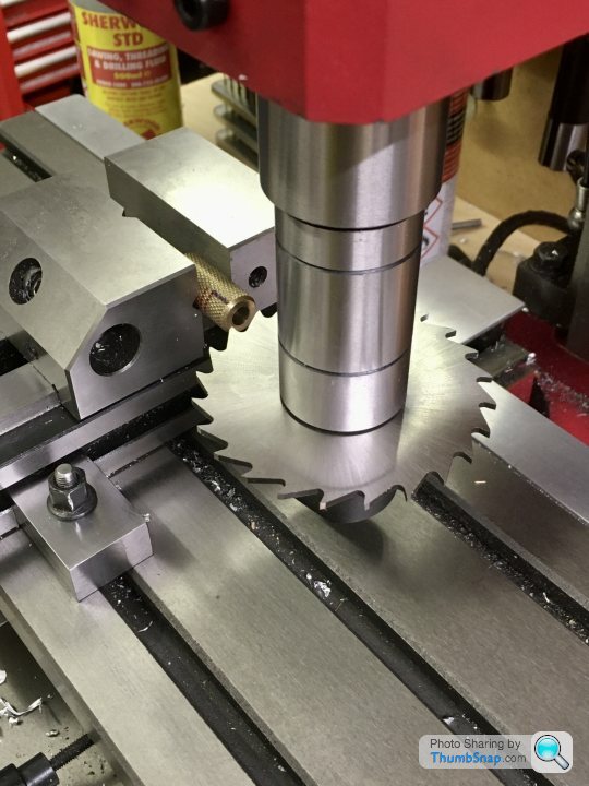
25215 forum posts 3105 photos 1 articles | I can't remember how much Stuarts allow for the cut but a saw about 1mm thick would be a reasonable middle of the road thickness - not too thin that it wanders excessively and not too thick that it loads the machine or removes too much metal. Don't get one with too many teeth as fine ones can clog and then start to wander something like 80mm dia and 30-35 teeth would be OK. This will do for both the big end and the half cut in the eccentric strap. I also like to give the sawn surfaces a skim with a flycutter if there is enough material to allow for it. |
| Dr_GMJN | 08/06/2020 22:33:33 |
1602 forum posts | Thanks both. I’m pretty sure a cutter will be able to make a better job of it than me with a hacksaw - never could saw square. Fly cutting the faces might be a tall order - they’re tiny. Maybe milling would be ok though? cheers. |
| Dr_GMJN | 14/06/2020 21:45:16 |
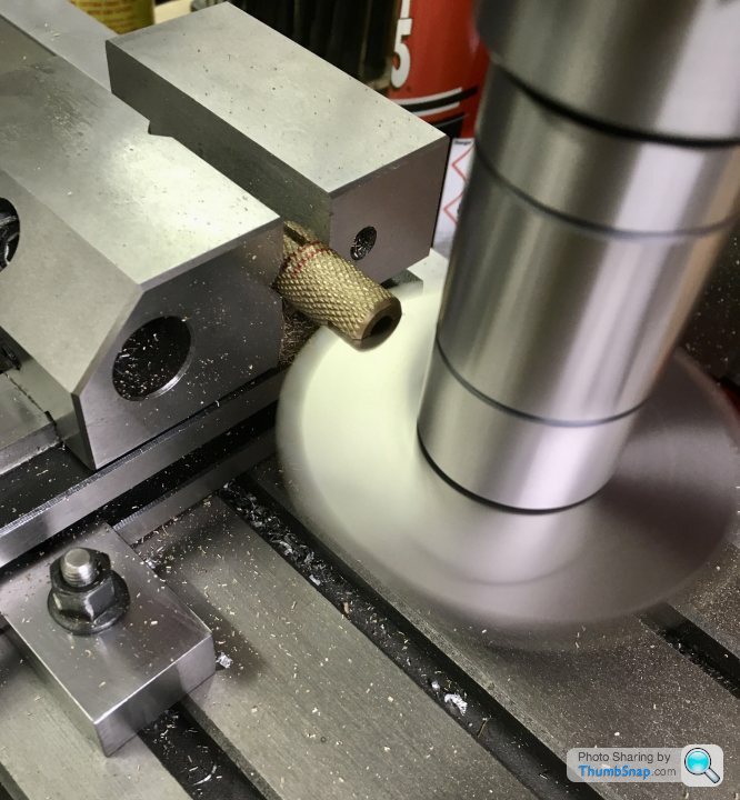
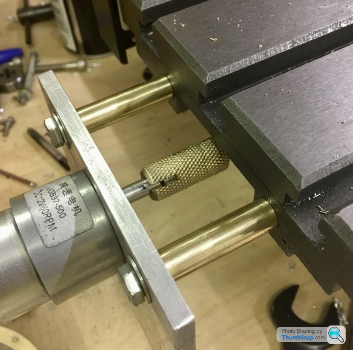
1602 forum posts | Got a bit distracted again last week, this time adding a motor to the x-feed screw. I found a ‘how to’ online, and half followed it - it's a much simplified version, but it'll do what I need it to. First job was to extend the lead screw and cross-drill it for a drive pin: Edited By Dr_GMJN on 14/06/2020 21:45:49 |
| Dr_GMJN | 14/06/2020 22:19:13 |
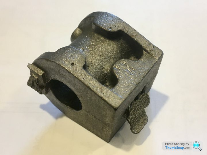
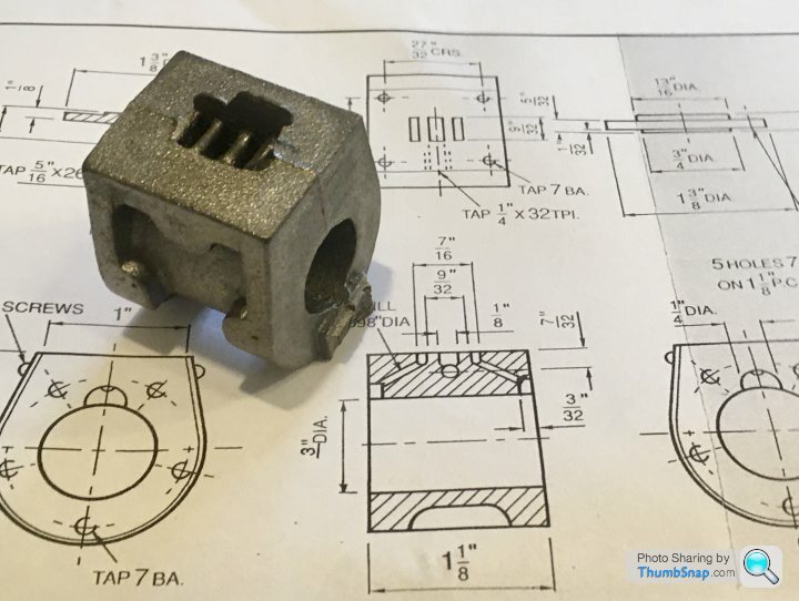
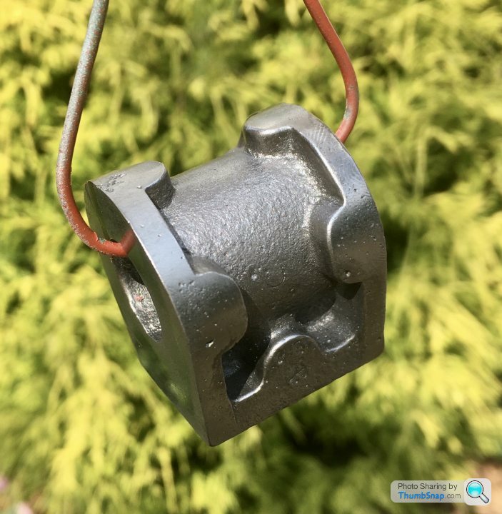
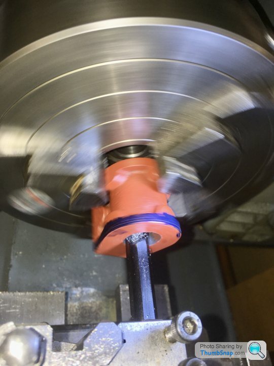
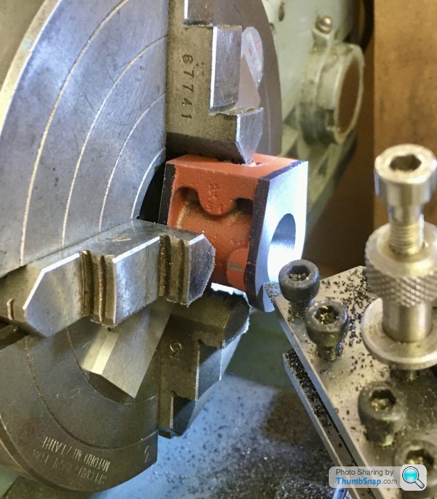
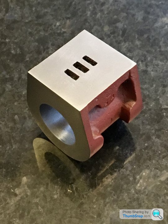
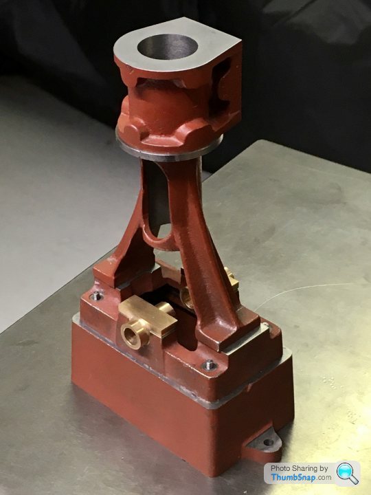
1602 forum posts | So on to one of the critical bits: the cylinder. The black casting is a bit rough: |
| Dr_GMJN | 14/06/2020 22:19:43 |
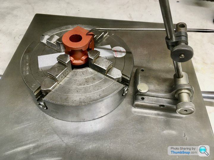
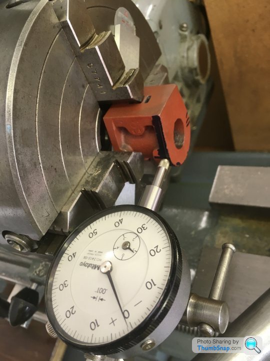
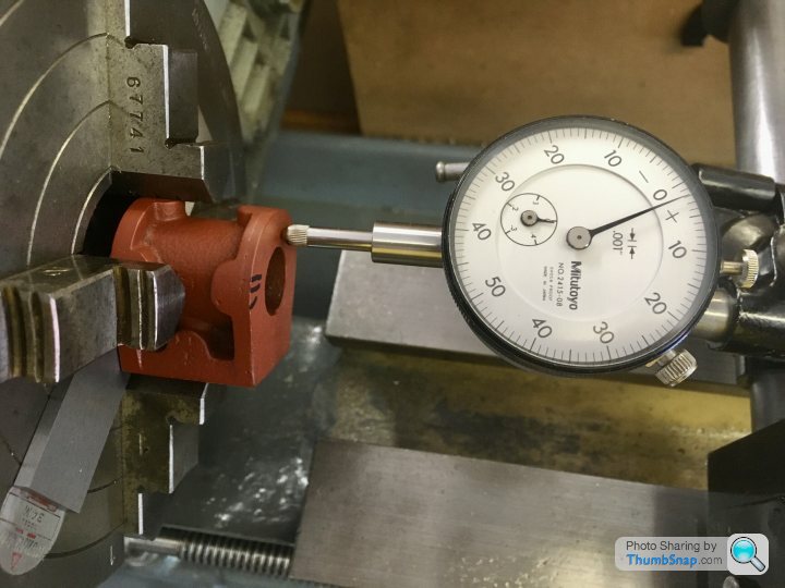
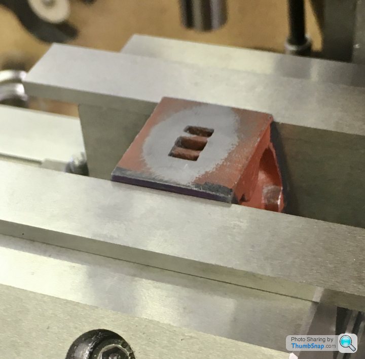
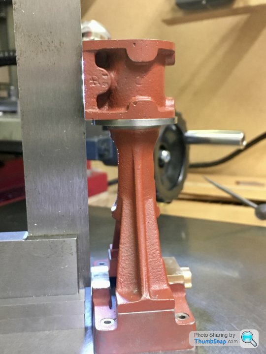
1602 forum posts | I thought about the next operation a lot, but it seemed like alignment by eye was as good as anything. I calculated the bore-face dimension using my bore size, and calculated how much to remove from the cast/filed face. I then scribed a line from the face using callipers. I put the cylinder in the vice and eyeballed the level using a parallel and slip gauge to form a datum plane. This was done both sides as a check, and it seemed to match: |
| Dr_GMJN | 14/06/2020 22:23:05 |
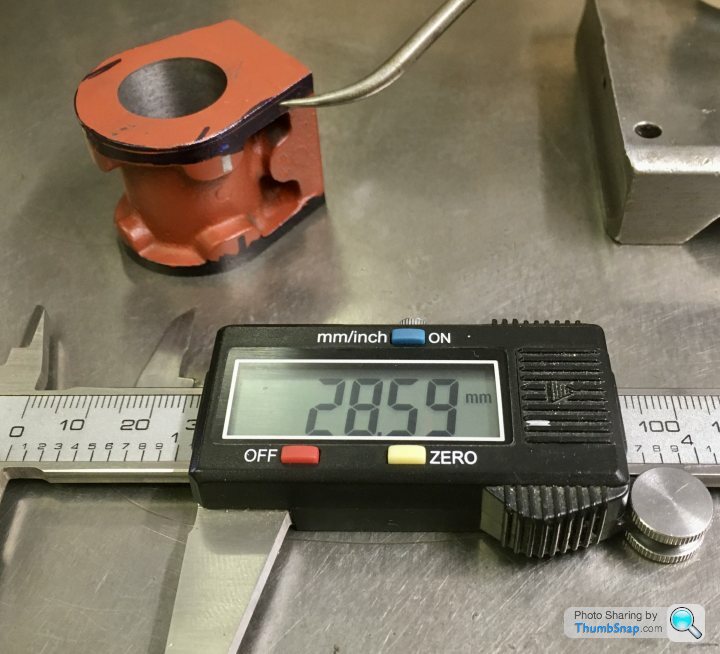
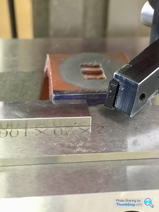
1602 forum posts | So to summarise what I've ended up with in terms of critical dimensions:
Bore: Drg: 19.05mm, Actual: 19.01mm, d= -0.04mm (-0,002" ) Bore Axis to Valve Face - Drg: 19.84mm, Actual: 19.565mm, d= -0.28mm (-0.011" ) Average Cylinder Depth - Drg: 28.575mm, Actual: 28.395, d= -0.18mm (-0.007" ) Max. Cylinder Depth Error (front/back): 0.17mm (0.007" ) Valve Port Face Width - Drg: 25.4mm, Actual: 25.4mm
Questions: 1) All things considered, are these figures good/bad/indifferent (bearing in mind there are no tolerances on the drawings)? 2) Do I need to correct anything? 3) I tried to machine to my marked-out lines on the casting, because I had no flat datums to touch on to, to use handwheels/DROs. What's the best procedure for this? I can only think to machine a datum, remove form the machine and measure, then re-fit to the machine and cut to depth using the read-outs (at least for parts that I can get access to measure). 4) Any comments on the methods I used, and how to avoid errors in future are, of course, welcome.
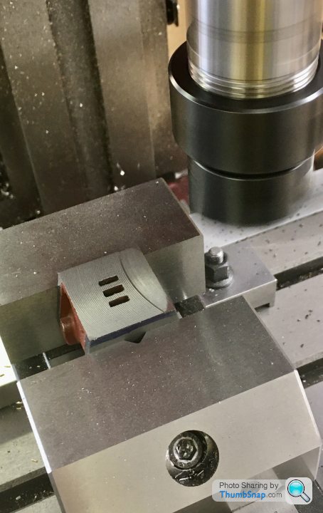
Next job: steam ports. Thanks! Edited By Dr_GMJN on 14/06/2020 22:51:16 |
| JasonB | 15/06/2020 13:28:53 |
25215 forum posts 3105 photos 1 articles | Posted by Dr_GMJN on 14/06/2020 22:23:05:
Bore: Drg: 19.05mm, Actual: 19.01mm, d= -0.04mm (-0,002" ) leaves a little for final hone/lap so will be fine, Expect your callipers are reading slightly under anyway Bore Axis to Valve Face - Drg: 19.84mm, Actual: 19.565mm, d= -0.28mm (-0.011" ) Not too critical can be compensated for by altering eccentric so it sits closer to bore axis by skimming a bit off if things bind on final assembly Average Cylinder Depth - Drg: 28.575mm, Actual: 28.395, d= -0.18mm (-0.007" ) Not critical, you could make spigot on top cover shorter bt same amount to compnsate but don't sweat over it Max. Cylinder Depth Error (front/back): 0.17mm (0.007" ) Would be nice to know where that crept in, possibly piston rod face not right back against 4-jaw face when machines, chuck jaws on the casting could have moved it slightly when tightened as would more than likely have contacted one flange before the other. Again should not affect running as you made sure bore and piston rod end where done at the same setting Valve Port Face Width - Drg: 25.4mm, Actual: 25.4mm Can't complain about that
Questions: 1) All things considered, are these figures good/bad/indifferent (bearing in mind there are no tolerances on the drawings)? See comments above 2) Do I need to correct anything? Ditto 3) I tried to machine to my marked-out lines on the casting, because I had no flat datums to touch on to, to use handwheels/DROs. What's the best procedure for this? I can only think to machine a datum, remove form the machine and measure, then re-fit to the machine and cut to depth using the read-outs (at least for parts that I can get access to measure). A line will always be a few thou thick and hard to split down the middle. Zeroing DRO after a cut and then taking out to measure what still needs to come off is OK, I do that. If your is resting on a surfac eyou could touch off on that and zero DRO then you know how far beyond that your finish cut needs to be. For cylinder length you could have put carrage against your new stop and touched the tool onto the 4-jaw's face, and then would back the topslide 1 11//8, noted reading and then faced until you got to that reading. 4) Any comments on the methods I used, and how to avoid errors in future are, of course, welcome.
Next job: steam ports. Thanks! Don't forget to poke some fuse wire down them to remove any remaining core sand Edited By Dr_GMJN on 14/06/2020 22:51:16
|
| Dr_GMJN | 15/06/2020 15:14:27 |
1602 forum posts | Thanks Jason, that's all good. I guess the non-parallel cylinder faces were a result of the jaws moving the workpiece. I'm pretty gutted about it, but I'll know to double check the seating next time. Question about lapping: Plain hardwood plug, tight running fit, #600 SiC and oil, run the cylinder along and back with the wood rotating? Same with the standard. But how do I lap the piston to the bore with the #1000 in terms of which bit to hold, and which bit to move, and how to align? Same with the crosshead and standard. How should the initial fit feel? Thanks. |
| JasonB | 15/06/2020 16:05:11 |
25215 forum posts 3105 photos 1 articles | That's it for the cylinder, lap in the lathe & run fairly slowly 100-200 rpm and just work it up and down the wooden lap. Piston, machine it but leave say 5thou over diameter and then mount onto the piston rod. Hold assembly by rod and get that running as true as you can and then take a couple of light skim cuts off the piston trying it into the cylinder after each until is will just enter. you can do the last bit by hand holding by the rod and work the piston into the bore with a tiny amount of 1000g and plenty of oil or it could be done on the lathe. I don't always lap the piston just leave it as the turned finish so upto you. Have a look at my Filer & Stowell thread a bit later and I'll show the cross head being lapped for that |
| Andrew Johnston | 15/06/2020 20:04:42 |
 7061 forum posts 719 photos | Out of idle curiosity I thought I'd measure the variation in width on my two recently squared up cylinders. Taking three points on each, one has a maximum variation of 0.1mm and the other is 0.05mm. Of course the variation doesn't matter. What is critical is that the bore is perpendicular to the face that controls piston alignment. What the other face, which is just a cover, does isn't important. Andrew |
| Chris Gunn | 15/06/2020 20:49:30 |
| 459 forum posts 28 photos | Hi, if you are worried about the end faces, you could always make a slightly tapered mandrel, and carefully polish the taper on, and taper it so the cylinder goes about 3/4 of the way on, put a bit of thin oil on it, then gently tap the cylinder block on tight while the mandrel is still in the chuck, and then take a skim off the end of the block, I guess only one end will be off, the end machined at the same time as the bore should be square. Whenever I make a Stuart engine, or any other for that matter, that is the way I always machine the second end. One the end is faced, remove the lot from the lathe and tap the mandrel out. Chris Gunn |
| Dr_GMJN | 15/06/2020 22:09:56 |
1602 forum posts | Thanks guys. I think regarding the cylinder I'll not try to correct it. It's a bit short anyway. If I mess up, I'll probably be way under size. If I had any excess at all, I'd probably do it using Chris's mandrel suggestion. There's a description of how to make a tapered mandrel on the Harold Hall website. Seems easy enough. I will know for next time though to do that by default. As I mentioned, there are different methods outlined online and in books, but I chose the one that seemed the most straightforward and paid the price. |
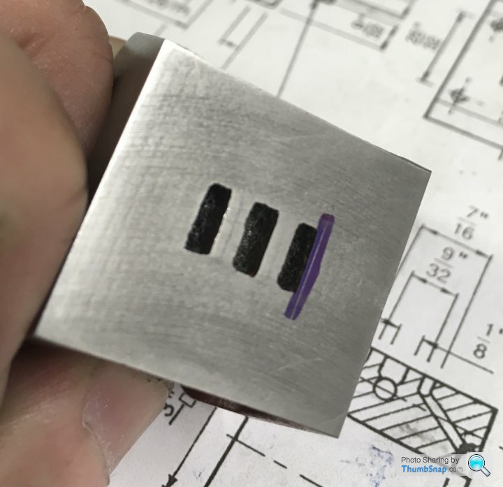
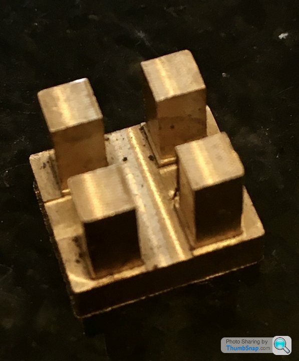
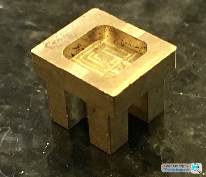
| Dr_GMJN | 15/06/2020 22:18:11 |
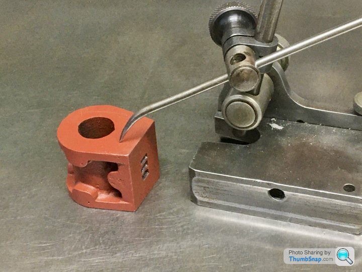
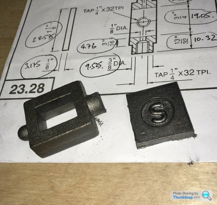
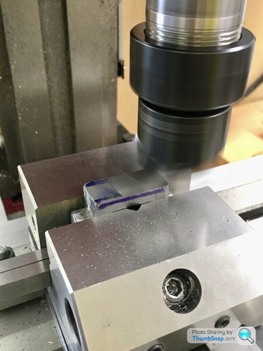
1602 forum posts | Had a spare hour and a half, so started on the valve chest, while the dimensions of the cylinder port face and lagging were still fresh in my mind: Edited By Dr_GMJN on 15/06/2020 22:20:03 |
| Dr_GMJN | 16/06/2020 09:09:12 |
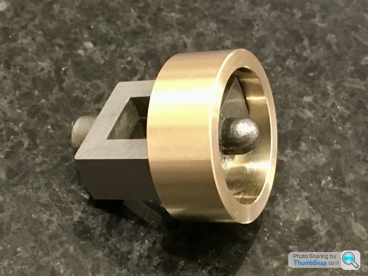
1602 forum posts | This is the valve slider as supplied in the kit: |
| JasonB | 16/06/2020 10:04:42 |
25215 forum posts 3105 photos 1 articles | Looks like someone has machined it for you, you can see the marks |
| Andrew Johnston | 16/06/2020 11:20:03 |
7061 forum posts 719 photos | A split bush is easier, and quicker, to make than a tapered arbor for holding work:
The split bush shown was used to face the gland to length, turn the boss to diameter and face the back of the flange. Width of the flange and height of the boss are parallel to better than 0.02mm. A split boss can also provide a high clamping force. Here's one being used to cut a 6DP gear in EN24:
Andrew |
| Dr_GMJN | 16/06/2020 11:46:15 |
1602 forum posts | Thanks Andrew, how do you make the bush? |


Please login to post a reply.
Magazine Locator
Want the latest issue of Model Engineer or Model Engineers' Workshop? Use our magazine locator links to find your nearest stockist!
Sign up to our Newsletter
Sign up to our newsletter and get a free digital issue.
You can unsubscribe at anytime. View our privacy policy at www.mortons.co.uk/privacy
Latest Forum Posts
- *Oct 2023: FORUM MIGRATION TIMELINE*
05/10/2023 07:57:11 - Making ER11 collet chuck
05/10/2023 07:56:24 - What did you do today? 2023
05/10/2023 07:25:01 - Orrery
05/10/2023 06:00:41 - Wera hand-tools
05/10/2023 05:47:07 - New member
05/10/2023 04:40:11 - Problems with external pot on at1 vfd
05/10/2023 00:06:32 - Drain plug
04/10/2023 23:36:17 - digi phase converter for 10 machines.....
04/10/2023 23:13:48 - Winter Storage Of Locomotives
04/10/2023 21:02:11 - More Latest Posts...
- View All Topics
Support Our Partners


Shopping Partners
Subscription Offer

Latest "For Sale" Ads
- Reeves** - Rebuilt Royal Scot by Martin Evans
by John Broughton
£300.00 - BRITANNIA 5" GAUGE James Perrier
by Jon Seabright 1
£2,500.00 - Drill Grinder - for restoration
by Nigel Graham 2
£0.00 - WARCO WM18 MILLING MACHINE
by Alex Chudley
£1,200.00 - MYFORD SUPER 7 LATHE
by Alex Chudley
£2,000.00 - More "For Sale" Ads...
Latest "Wanted" Ads
- D1-3 backplate
by Michael Horley
Price Not Specified - fixed steady for a Colchester bantam mark1 800
by George Jervis
Price Not Specified - lbsc pansy
by JACK SIDEBOTHAM
Price Not Specified - Pratt Burnerd multifit chuck key.
by Tim Riome
Price Not Specified - BANDSAW BLADE WELDER
by HUGH
Price Not Specified - More "Wanted" Ads...
Get In Touch!
Do you want to contact the Model Engineer and Model Engineers' Workshop team?
You can contact us by phone, mail or email about the magazines including becoming a contributor, submitting reader's letters or making queries about articles. You can also get in touch about this website, advertising or other general issues.
Click THIS LINK for full contact details.
For subscription issues please see THIS LINK.
Digital Back Issues


Donate

 Register
 Log-in
Model Engineer Magazine
- Percival Marshall
- M.E. History
- LittleLEC
- M.E. Clock

ME Workshop
- An Adcock
- & Shipley
- Horizontal
- Mill

Subscribe Now
- Great savings
- Delivered to your door

Pre-order your copy!
- Delivered to your doorstep!
- Free UK delivery!
All Forum Topics > Work In Progress and completed items > Stuart 10V Build Log - Complete Beginner...