Forum sponsored by:

Improved Experimental Pendulum
| duncan webster | 20/04/2023 22:50:23 |
| 5307 forum posts 83 photos | Posted by Michael Gilligan on 20/04/2023 22:40:02:
Posted by duncan webster on 20/04/2023 22:29:18:
[…] Agreed it won't twang if you're careful about impulsing, but Michael's post just said it won't twang. I must read other's posts more carefully re 2 strings! […] . You do me [or perhaps Joe] a dis-service, Duncan ! Michael said no such thing. MichaelG. I really must concentrate, it was Joe who said no twanging possible. Steel rules are different, the restoring force is due to bending in the rule. In a light string it is the tension that provides the restoring force. |
| Michael Gilligan | 20/04/2023 22:57:47 |
 23121 forum posts 1360 photos | Some homework for those who were not paying attention in class: **LINK** https://salfordacoustics.co.uk/sound-waves/waves-on-a-string MichaelG. . Edit: __ and if you want more: this is impressive: https://www.acs.psu.edu/drussell/Demos/Pluck-Fourier/Pluck-Fourier.html Edited By Michael Gilligan on 20/04/2023 23:18:40 |
| Joseph Noci 1 | 20/04/2023 23:01:52 |
| 1323 forum posts 1431 photos | Posted by duncan webster on 20/04/2023 22:29:18:
I just hung a 4 kg vice from 1.4 m of fabric tape (couldn't find any string) top hooked to my lifting beam. If plucked in the middle it vibrates. Not for very long, too much damping. Agreed it won't twang if you're careful about impulsing, but Michael's post just said it won't twang. I must read other's posts more carefully re 2 strings! Again you'd need to be careful with impulsing to make sure the bob didn't rock around the string/bob interface what is the mass of your bob SOD? 200g? 400g?? Duncan, hang that from your 1.4meter tape and try twang the tape... its all relative. A thin CF rod is a High Q device - as is a harp/guitar string which is under far more tension than a 400g weight would set it at, The Q of a guitar string under tension is also far greater than a single CF strand under very low tension. Its also rather difficult to twang a guitar string right at the end of the string - at the bridge/string contact or at the tuning peg and implusing the bob is nicely at the end of the string..
Edited By Joseph Noci 1 on 20/04/2023 23:09:05 |
| duncan webster | 20/04/2023 23:18:54 |
| 5307 forum posts 83 photos | My fabric tape is a lot heavier than the 10um filament suggested. If there is a mechanism which makes a rod vibrate, I can't see why a filament won't. I said before it's unlikely to matter, even SOD's little bob will dwarf the mass of the filament. Edited By duncan webster on 20/04/2023 23:44:23 |
| Joseph Noci 1 | 21/04/2023 07:08:07 |
| 1323 forum posts 1431 photos | Posted by Michael Gilligan on 20/04/2023 22:57:47:
Some homework for those who were not paying attention in class: **LINK** https://salfordacoustics.co.uk/sound-waves/waves-on-a-string MichaelG. . Edit: __ and if you want more: this is impressive: Edited By Michael Gilligan on 20/04/2023 23:18:40 At the risk of drifting , I would say that the boundary conditions for a plucked string are very different to the pendulum - the plucked string is well and truly fixed at both ends, and has an appreciable tension - a 0.01 diameter E string sits at around 56N tension on 'a' guitar- assume SOD's bob is 400g, the fibre endures 4N -at 1meter length, and the fibre is 10um, and the bob is nowhere near fixed, and the fibre considerably more damped....Good luck to Mr Fourier on this one. |
| Michael Gilligan | 21/04/2023 07:59:16 |
23121 forum posts 1360 photos | The video that’s embedded on the second page [Standing Waves] of my ‘homework’ link is worth watching It features a DiY shaker [clearly incapable of providing great tension in the string] and demonstrates modes of vibration very nicely. Nothing is as simple as it first appears. MichaelG. . For the convenience of those rushing through their homework: Edited By Michael Gilligan on 21/04/2023 08:20:21 |
| SillyOldDuffer | 21/04/2023 11:02:31 |
| 10668 forum posts 2415 photos | Posted by Joseph Noci 1 on 21/04/2023 07:08:07:
Posted by Michael Gilligan on 20/04/2023 22:57:47:...
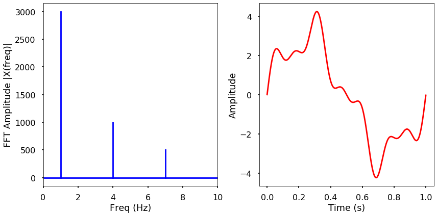
... assume SOD's bob is 400g, the fibre endures 4N -at 1meter length, and the fibre is 10um, and the bob is nowhere near fixed, and the fibre considerably more damped....Good luck to Mr Fourier on this one. The actual masses are: Brass Rod top (connecting to spring) = 9g I plead guilty to introducing the unscientific word 'twanging', by which I meant any unwanted oscillations in the pendulum assembly. They cover the bob swinging in ellipses and visual bending of the rod when the bob is impulsed strongly. Ideally the bob swings in straight lines of equal amplitude, and the period isn't affected by the rod flexing. Or anything else, such as the frame. Ideally precision pendulum clocks should made be as rigid as possible and bolted to a heavy wall. I believe Jean-Baptiste Joseph Fourier confirms my view that the pendulum has more than one mode of oscillation. (For anyone unfamiliar with Fourier, he derived the maths necessary to extract the original frequencies from a mixture of frequencies, plus their relative proportions. In this example, the red wave on the right it shown as it would be displayed by an oscilloscope. It's a mix of 3 frequencies, but what are they?
The blue chart on the left is the Fourier transform, displaying the signal as a frequency spectrum. It shows the 3 frequencies are 1Hz, 4Hz and 7Hz, that the 1Hz signal is 3x stronger than the 4Hz component, and the 7Hz component is half the amplitude of the 4Hz wave.) Applying FFT to my log files produces graphs like this example:
A perfect pendulum FFT should only show one frequency. Mine shows two main frequencies, one of which is half the true period*. It also shows 9 smaller components that appear to be related to each other. (Ignore the big zero spike - it's a a mathematical artefact.) An explanation of the small frequencies might be the pendulum picking up ground vibrations. I doubt it; more likely they are caused by mechanical imperfections in the build, or which there were several! I think the most likely explanation of the harmonically related pair is the rod vibrating. * Need to confess I suspect the frequency scale of my graph is out by a factor of two: probably 1.2Hz and 2.4Hz rather than 0.6Hz and 1.2Hz. But I'm confident the FFT analysis shows my pendulum vibrates in more than one mode, Q about 9600. Dave
Edited By SillyOldDuffer on 21/04/2023 11:06:06 |
| SillyOldDuffer | 22/04/2023 20:39:01 |
| 10668 forum posts 2415 photos | Thought I'd made significant progress today until I made the mistake of testing it! Wiring needs a tidy up but the slotted beam breaker works well.
Bad news is the electromagnet isn't powerful enough to self-start the pendulum, which is essential after the works are sealed inside the vacuum. Can't think of a simple answer and will have to sleep on it. Pesky details...
Dave
Edited By SillyOldDuffer on 22/04/2023 20:39:17 |
| duncan webster | 22/04/2023 23:06:26 |
| 5307 forum posts 83 photos | Engineers solution, tip it up to get it swinging. Won't appeal to the pendulistas. |
| blowlamp | 22/04/2023 23:09:42 |
 1885 forum posts 111 photos | Posted by SillyOldDuffer on 22/04/2023 20:39:01:
Thought I'd made significant progress today until I made the mistake of testing it! Wiring needs a tidy up but the slotted beam breaker works well.
Bad news is the electromagnet isn't powerful enough to self-start the pendulum, which is essential after the works are sealed inside the vacuum. Can't think of a simple answer and will have to sleep on it. Pesky details...
Dave
Edited By SillyOldDuffer on 22/04/2023 20:39:17 Pass a magnet near it? |
| Joseph Noci 1 | 23/04/2023 07:20:46 |
| 1323 forum posts 1431 photos | Posted by SillyOldDuffer on 22/04/2023 20:39:01:
Bad news is the electromagnet isn't powerful enough to self-start the pendulum, which is essential after the works are sealed inside the vacuum. Can't think of a simple answer and will have to sleep on it. Post a photo of the mechanical layout of E-Magnet and bob positions and give some indication of distance tween the two. Also some mechanical details of the E-Magnet - size, core size,No of turns, resistance, and your drive cct ( just the drive part, not the cpu etc... |
| John Haine | 23/04/2023 08:31:53 |
| 5563 forum posts 322 photos | Assuming it's strong enough to keep it swinging it will self start if you pulse the magnet close to the resonant frequency. I did this originally on my synchronome derived clock as the gravity roller rested half way down the pallet ramp when the pendulum was stationary. Even though the Q is about 12000 I found that impulsing at the period time just using a delay statement in the Arduino would get it up to an amplitude where it began to activate the opto sensor within a couple of minutes. Once it started to get opto pulses it jumped to its run mode. |
| Michael Gilligan | 23/04/2023 09:32:40 |
23121 forum posts 1360 photos | Posted by SillyOldDuffer on 22/04/2023 20:39:01:
[…] Bad news is the electromagnet isn't powerful enough to self-start the pendulum, […] . It’s probably that massive lump of Iron and the steel rod, upsetting the field ! MichaelG. |
| Martin Kyte | 23/04/2023 09:45:20 |
 3445 forum posts 62 photos | I can’t remember the layout of your impulsing coil but if it is directly below the pendulum and acting attractively then when the system is at rest there will be very little couple to start the swing. If you give an initial reverse pulse and repulse the bob there should be some initial disturbance as the system would be unstable. Once you have a small oscillation the normal direction impulsing should be more effective. |
| SillyOldDuffer | 23/04/2023 12:19:13 |
| 10668 forum posts 2415 photos | Posted by Joseph Noci 1 on 23/04/2023 07:20:46:
Posted by SillyOldDuffer on 22/04/2023 20:39:01:
Bad news is the electromagnet isn't powerful enough to self-start the pendulum, which is essential after the works are sealed inside the vacuum. Can't think of a simple answer and will have to sleep on it. Post a photo of the mechanical layout of E-Magnet and bob positions and give some indication of distance tween the two. Also some mechanical details of the E-Magnet - size, core size,No of turns, resistance, and your drive cct ( just the drive part, not the cpu etc... Well, this is a side mounted electromagnet intended to impulse a 95g steel bob on a 240mm rod suspended inside a vacuum chamber made from a 4" diameter PVC soil pipe (103mm):
The electromagnet and beam break tubes are held in a 3D-printed 'chariot'. The present design is scaled up from the earlier build, and puts the magnet about 15mm away from the stopped bob. This is a mistake, because it moves the magnet further away from the bob, which is also nearly 5x heavier than the original. The electromagnet is the coil and core removed from a small 5V relay common as muck in Arduino modules, type SRD05VDC. The coll draws 75mA and my driver circuit is basic using junk box components:
Results from a few experiments this morning:
Not too difficult to try, so I will. Fair amount of work had I milled the chariot from metal, but it's 3D printed from an easily changed CAD model. Be a delay - I'm out this afternoon. Dave |
| Bazyle | 23/04/2023 12:32:04 |
 6956 forum posts 229 photos | If the only forces on the pendulum were gravity and the force from your electromagnet it must start moving, even if it takes weeks to be visible. However you also have vibrations etc which should average out but then you have the force from the suspension spring. Can the non-movement be used to calculate anything useful about the force from this spring? If you had an induction coil near the metal of the bob (at rest) I assume it would produce an output relating to ambient interference eg from you walking past with a bunch of magnetised keys but also from tiny movements due to vibrations etc. Would this tell you anything useful, particularly would it show peaks relating to its period and other modes? |
| John Haine | 23/04/2023 13:19:26 |
| 5563 forum posts 322 photos | Posted by SillyOldDuffer on 23/04/2023 12:19:13:
Posted by Joseph Noci 1 on 23/04/2023 07:20:46:
Not too difficult to try, so I will. Fair amount of work had I milled the chariot from metal, but it's 3D printed from an easily changed CAD model. Be a delay - I'm out this afternoon. Dave I just looked back at the code (which I no longer use as it's easier just to nudge the bob) and it was impulsed 30 times at 2s intervals, so took a minute to get going with enough amplitude to operate the electronics. To put that in perspective the pendulum normally operates at 1 impulse per minute. So I don't think it should necessarily take a long time. |
| Joseph Noci 1 | 23/04/2023 15:07:09 |
| 1323 forum posts 1431 photos | How close to the E-magnet would the bob be in 'normal' operation before the bob turns around? |
| Bazyle | 23/04/2023 15:57:14 |
6956 forum posts 229 photos | You said the external magnet operation was too violent etc. How about making a sort of gravity arm that can nudge the pendulum but is lifted by the manual use of the external magnet, applied out of range of the bob. I notice your impulse is driven by a simple on/off line. Does the sudden application of the force cause the ringing you saw in your FFt. It is rather like being hit by a hammer rather than a gentle perhaps sinusoidal ramp up and down. |
| blowlamp | 23/04/2023 16:29:48 |
1885 forum posts 111 photos | "Blowlamp's idea works - a permanent magnet from an oven magnetron is just powerful enough to grab the bob from outside the case. Unfortunately the action on release is horribly violent; the bob smashes hard into the internal electromagnet."
Did you try applying the magnet from the opposite side, so the pendulum is drawn into light contact with the electromagnet before release? Some felt on the electromagnet might help to soften any contact with the bob. Where abouts in the swing is impulse applied - is it at one extremitiy, or close to bottom dead centre? Martin. |


Please login to post a reply.
Magazine Locator
Want the latest issue of Model Engineer or Model Engineers' Workshop? Use our magazine locator links to find your nearest stockist!
Sign up to our Newsletter
Sign up to our newsletter and get a free digital issue.
You can unsubscribe at anytime. View our privacy policy at www.mortons.co.uk/privacy
Latest Forum Posts
- *Oct 2023: FORUM MIGRATION TIMELINE*
05/10/2023 07:57:11 - Making ER11 collet chuck
05/10/2023 07:56:24 - What did you do today? 2023
05/10/2023 07:25:01 - Orrery
05/10/2023 06:00:41 - Wera hand-tools
05/10/2023 05:47:07 - New member
05/10/2023 04:40:11 - Problems with external pot on at1 vfd
05/10/2023 00:06:32 - Drain plug
04/10/2023 23:36:17 - digi phase converter for 10 machines.....
04/10/2023 23:13:48 - Winter Storage Of Locomotives
04/10/2023 21:02:11 - More Latest Posts...
- View All Topics
Support Our Partners


Shopping Partners
Subscription Offer

Latest "For Sale" Ads
- Reeves** - Rebuilt Royal Scot by Martin Evans
by John Broughton
£300.00 - BRITANNIA 5" GAUGE James Perrier
by Jon Seabright 1
£2,500.00 - Drill Grinder - for restoration
by Nigel Graham 2
£0.00 - WARCO WM18 MILLING MACHINE
by Alex Chudley
£1,200.00 - MYFORD SUPER 7 LATHE
by Alex Chudley
£2,000.00 - More "For Sale" Ads...
Latest "Wanted" Ads
- D1-3 backplate
by Michael Horley
Price Not Specified - fixed steady for a Colchester bantam mark1 800
by George Jervis
Price Not Specified - lbsc pansy
by JACK SIDEBOTHAM
Price Not Specified - Pratt Burnerd multifit chuck key.
by Tim Riome
Price Not Specified - BANDSAW BLADE WELDER
by HUGH
Price Not Specified - More "Wanted" Ads...
Get In Touch!
Do you want to contact the Model Engineer and Model Engineers' Workshop team?
You can contact us by phone, mail or email about the magazines including becoming a contributor, submitting reader's letters or making queries about articles. You can also get in touch about this website, advertising or other general issues.
Click THIS LINK for full contact details.
For subscription issues please see THIS LINK.
Digital Back Issues


Donate

 Register
 Log-in
Model Engineer Magazine
- Percival Marshall
- M.E. History
- LittleLEC
- M.E. Clock

ME Workshop
- An Adcock
- & Shipley
- Horizontal
- Mill

Subscribe Now
- Great savings
- Delivered to your door

Pre-order your copy!
- Delivered to your doorstep!
- Free UK delivery!
All Forum Topics > Clocks and Scientific Instruments > Improved Experimental Pendulum