Forum sponsored by:

Stuart 10V Build Log - Complete Beginner...
| Dr_GMJN | 03/06/2020 23:17:07 |
 1602 forum posts | One other question on the standard while I'm at it: I don't have a rotary table yet, but I'll need to drill the cylinder mounting holes. If I can get the center of the bore and zero my DROs on it, would it be accurate enough to use X&Y co-ordinates obtained from Autocad/Creo/Fusion/whatever I can remember how to use on the day, to get the holes on the correct PCD, and expect them to match the cylinder and upper and lower covers? |
| JasonB | 04/06/2020 07:09:34 |
 25215 forum posts 3105 photos 1 articles | If you have afully functioning DRO then just use the PCD function. If simple scales with just a readout then co-ordinates will be fine, if you have a Zeuz book that gives simple formula to get various PCDs and a 6hole can even be done in your head as it's just equilateral triangles. The Standard I would hold in the 4 jaw to turn the feet and use a long length of studding right through the spindle to retain it or better still make a plug for the bottom and use tailstock ctr, if just holding on a bolt then also drill the end and use tailstock support. Usual way to set the top running true was to drive a lump of wood into the end, file flush and then strike say four arcs in from the edge and eyeball the ctr from where they meet, you can then set the ctr to run true by gently tapping the part into position with the fixings nipped up. |
| Dr_GMJN | 04/06/2020 09:45:36 |
1602 forum posts | Posted by JasonB on 04/06/2020 07:09:34:
If you have afully functioning DRO then just use the PCD function. If simple scales with just a readout then co-ordinates will be fine, if you have a Zeuz book that gives simple formula to get various PCDs and a 6hole can even be done in your head as it's just equilateral triangles. The Standard I would hold in the 4 jaw to turn the feet and use a long length of studding right through the spindle to retain it or better still make a plug for the bottom and use tailstock ctr, if just holding on a bolt then also drill the end and use tailstock support. Usual way to set the top running true was to drive a lump of wood into the end, file flush and then strike say four arcs in from the edge and eyeball the ctr from where they meet, you can then set the ctr to run true by gently tapping the part into position with the fixings nipped up. Thanks Jason, It's 5 holes on the PCD. The DROs are from individual x, y & z scales I fitted a few weeks ago (the cheap ones). They read to 0.01mm. I have no idea about accuracy or repeatabiity though. I'd totally forgotten about the Zeus book - I got one at uni and never looked at it since. I think I'll use the formula in there, just so I didn't waste my money back in 1990. |
| Martin Connelly | 04/06/2020 11:26:03 |
 2549 forum posts 235 photos | The Zeus books are a bit of an anachronism nowadays. I have two, the older one has log tables, sin, cos and tan tables. The later one has tan tables and lists of numerical and CNC control codes. I still use them as a useful reference but some of their function has been superseded by modern technology. The drilling of holes on a PCD is an example. To get the coordinates of a hole on a PCD from an angle and the PCD they are the PCD x cos(angle) and PCD x sin(angle). With the availability of calculators with trig functions (we are talking here of stand alone calculators and those on computers and mobile phones) to calculate these X and Y coordinates the use of the Zeus books has reduced. Before calculators the machinist had to do the calculations using the tables for sin and cos to get these values then get the values for coordinates by multiplication using the log tables. We seem to have a system for rotary tables (PCD and angle) and a system for XY tables with DROs (X and Y coordinates). Older drawings are based on the former system. Newer ones drawn with cad can cater for both. As drawings created with CAD can be used to just put the dimensions from the centre of a PCD (or any other datum) straight onto the drawing. If you have access to CAD then often a quick drawing with dimensions calculated by the CAD program is quicker than doing a lot of calculations yourself. Martin C |
| JasonB | 04/06/2020 13:02:47 |
25215 forum posts 3105 photos 1 articles | Or if you don't want to spend half an hour trying to remember your CAD program there are plenty of simple calculators on line that will give the co-ordinates. |
| Dr_GMJN | 04/06/2020 13:40:50 |
1602 forum posts | I calculated them from the Zeus book, and confirmed them with Autocad. Only took 15 minutes and they both correlate. Thanks. |
| Dr_GMJN | 04/06/2020 22:26:39 |
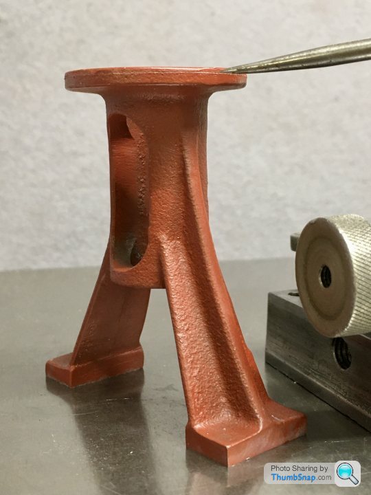
1602 forum posts | Moved on to the standard - I’ll do all the base drilling at the same time. Question about the machined bore for the slider - and for the main cylinder for that matter: I'm thinking to machine them to a 'close enough' dimension to the drawing, concentrating on surface finish rather than absolute accuracy, and then make the piston/slider to suit whatever bore diameter I end up with. I could machine small amounts off the piston/slider until I get a good fit - checking by repeatedly machining and test fitting in the bored parts. Is this OK or totally bad practice? I doubt I could machine the parts in isolation to a dimension and get them to fit, so I don't think I've got much choice. There are no tolerances on the drawings anyway, and even it there were, I doubt I could hit them! Thanks. |
| JasonB | 05/06/2020 06:53:38 |
25215 forum posts 3105 photos 1 articles | Aim for nominal size but a bit either way won't matter as the finish is more important then make the rest to suit. |
| TiddlerTad | 05/06/2020 10:29:08 |
| 55 forum posts 2 photos | Hi - I made a 10V last year and produced a series of YouTube videos. Some of my machining methods might not be the best, but it runs as sweet as a nut. I also added a reversing mechanism which definitely makes the engine more interesting. The link to my video series is here They might be of interest. Good luck with the build. Cheers. Andrew |
| Dr_GMJN | 05/06/2020 10:37:36 |
1602 forum posts | Posted by Andrew Whale 1 on 05/06/2020 10:29:08:
Hi - I made a 10V last year and produced a series of YouTube videos. Some of my machining methods might not be the best, but it runs as sweet as a nut. I also added a reversing mechanism which definitely makes the engine more interesting. The link to my video series is here They might be of interest. Good luck with the build. Cheers. Andrew Thanks Andrew! - It's Garth here: I've contacted you a couple of times when I was looking at the SX2P, and more recently when setting it up. I pretty much followed your lead on adding the DRO scales, making the vice clamps, and using the bolt method for machining the standard. Your videos were my "go-to" references when planning this build, and with the additional help of forum members here I'm making steady (but slow) progress. Cheers! |
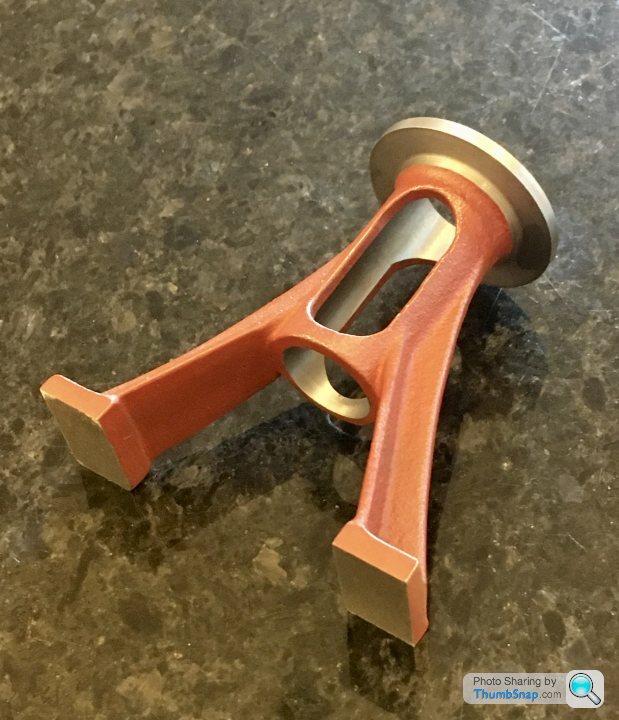
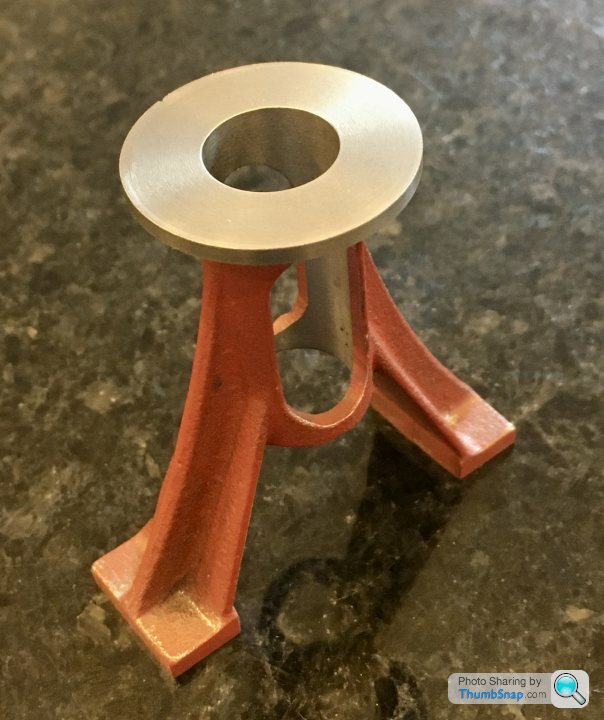
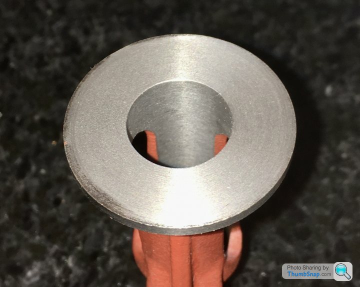
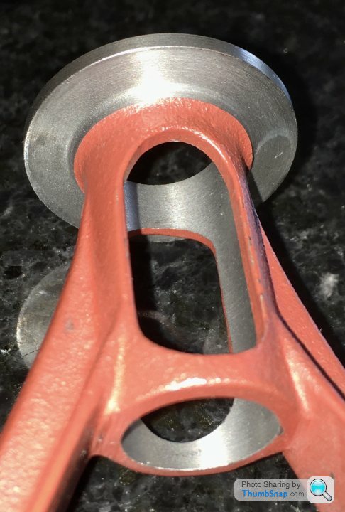
| Dr_GMJN | 05/06/2020 17:52:17 |
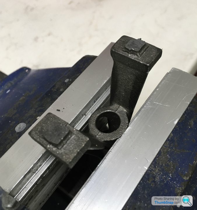
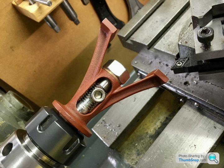
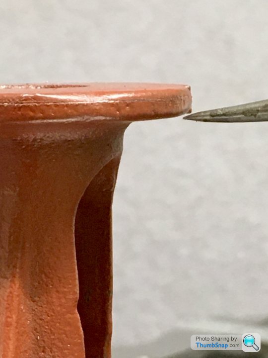
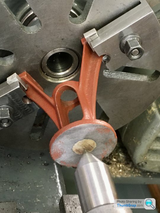
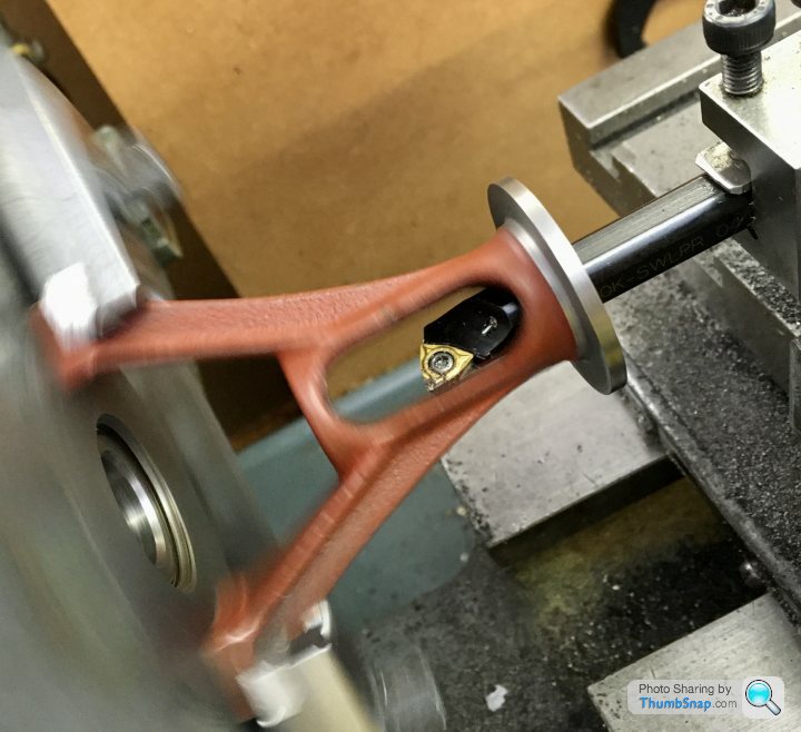
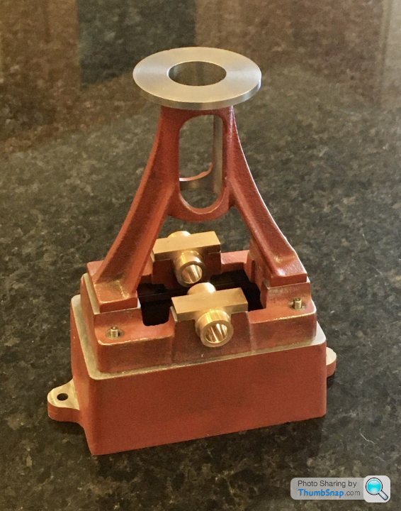
1602 forum posts | I took a bit more off the feet, and then prepared the casting for fitting to the faceplate by hammering a dowel plug Into the end (as suggested), and marking the centre using callipers. I modded my vice clamps and used them to secure. It was easy to align everything to a centre in the tailstock: Quick question: before machining the slider to suit the bore, do I need to do any other finishing of the bore? It's a nice finish as far as I'm concerned, but it will still have machining marks in it. Thanks all! |
| Mark Gould 1 | 05/06/2020 18:01:32 |
| 231 forum posts 131 photos | Loving your progress Garth, you seem to be doing everything right! Quick question though, how do you get all of your photos to be oriented correctly? I have the occasional one that turns out rotated when I upload it to my album. Sorry to hijack this lovely build thread with a question. Mark |
| JasonB | 05/06/2020 18:23:19 |
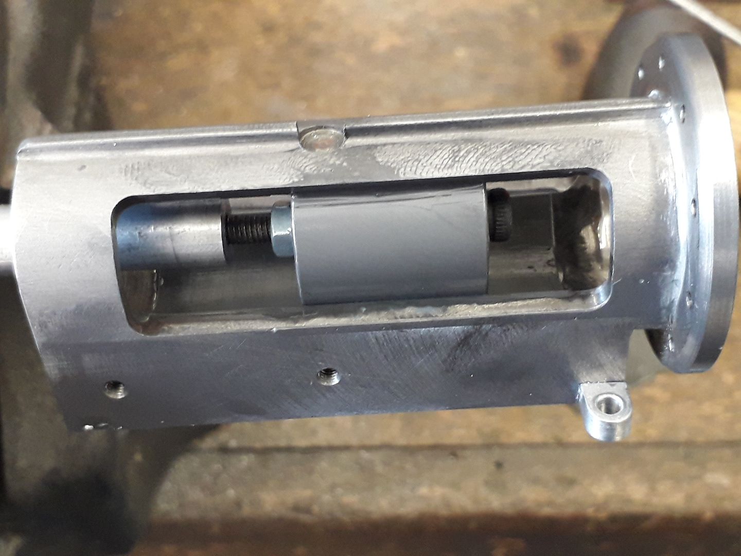
25215 forum posts 3105 photos 1 articles | It would not hurt to lap the trunk guide, this will give a smoother surface and also help remove any taper if present. Simple way would be to turn a piece of hardwood to a good fit in the trunk guild, charge it with some oil and 600g silicon carbide powder and work the standard up an down it with the lap slowly rotating. When it comes to the cross head that can also be lapped into the trunk guide with some 1000g for the best fit. These are cylinders being lapped, aluminium lap in this case
And the embryo cross head of my latest engine being lapped into the trunk guide
|
| Dr_GMJN | 05/06/2020 19:34:37 |
1602 forum posts | Posted by Mark Gould 1 on 05/06/2020 18:01:32:
Loving your progress Garth, you seem to be doing everything right! Quick question though, how do you get all of your photos to be oriented correctly? I have the occasional one that turns out rotated when I upload it to my album. Sorry to hijack this lovely build thread with a question. Mark Mark, no problem. I post an abbreviated build log on another (not engineering) model forum, and upload the images there. I copy and paste here. Never had an issue so far. Cheers! |
| Dr_GMJN | 05/06/2020 19:37:35 |
1602 forum posts | Posted by JasonB on 05/06/2020 18:23:19:
It would not hurt to lap the trunk guide, this will give a smoother surface and also help remove any taper if present. Simple way would be to turn a piece of hardwood to a good fit in the trunk guild, charge it with some oil and 600g silicon carbide powder and work the standard up an down it with the lap slowly rotating. When it comes to the cross head that can also be lapped into the trunk guide with some 1000g for the best fit. These are cylinders being lapped, aluminium lap in this case
And the embryo cross head of my latest engine being lapped into the trunk guide
Thanks Jason. Any rules of thumb for length of the lap eg 1.5x diameter or something? By lapping, how are we avoiding or even reducing taper? Just picking up more on smaller internal diameters? Thanks. |
| JasonB | 05/06/2020 20:05:27 |
25215 forum posts 3105 photos 1 articles | If making a simple wooden lap then it can be made as long as the trunk guide or even a bit more a sit's cheap enough. If metal then yes something like 1.5 x D would be a minimum. That trunk guide I showed above at 22mm dia was done with a length of copper water pipe about twice it's length. The theory is that the lap is parallel and does the cutting so it will remove high spots and/or the smaller diameter parts of the hole. very good thread on lapping over on MEM forum here though mostly about expanding laps. |
| Dr_GMJN | 05/06/2020 20:15:47 |
1602 forum posts | Ok, but if I’m turning the wood on the same lathe I’m machining the part, why would it be any more parallel than the part? |
| JasonB | 05/06/2020 20:17:20 |
25215 forum posts 3105 photos 1 articles | Bores have a habit of tapering even on lathes that will turn a parallel OD. |
| Dr_GMJN | 05/06/2020 22:53:07 |
1602 forum posts | Posted by JasonB on 05/06/2020 20:17:20:
Bores have a habit of tapering even on lathes that will turn a parallel OD. OK. I guess the real test starts when I have to machine one part to fit into another... I think I might get on with the cylinder, covers and valve box - get all the cast parts fitted together to give myself some more practice, then start on the moving parts. |
| Dr_GMJN | 05/06/2020 22:57:36 |
1602 forum posts | Posted by Dr_GMJN on 05/06/2020 22:53:07:
Posted by JasonB on 05/06/2020 20:17:20:
Bores have a habit of tapering even on lathes that will turn a parallel OD. OK. I guess the real test starts when I have to machine one part to fit into another... I think I might get on with the cylinder, covers and valve box - get all the cast parts fitted together to give myself some more practice, then start on the moving parts. I have noticed that once I've made a cut, going back over at the same depth setting cuts again, and again, and again. I guess it's gradually knocking off the peaks of the surface. I can't think it's much to do with thermal expansion at the speeds I'm using, or deflection at the depths I'm using. It's strange to see. Once a bore is machined to size, is a 'finishing cut' defined as another at the same depth setting (as per above), or is it a final very thin cut to the final size? Thanks. |


Please login to post a reply.
Magazine Locator
Want the latest issue of Model Engineer or Model Engineers' Workshop? Use our magazine locator links to find your nearest stockist!
Sign up to our Newsletter
Sign up to our newsletter and get a free digital issue.
You can unsubscribe at anytime. View our privacy policy at www.mortons.co.uk/privacy
Latest Forum Posts
- *Oct 2023: FORUM MIGRATION TIMELINE*
05/10/2023 07:57:11 - Making ER11 collet chuck
05/10/2023 07:56:24 - What did you do today? 2023
05/10/2023 07:25:01 - Orrery
05/10/2023 06:00:41 - Wera hand-tools
05/10/2023 05:47:07 - New member
05/10/2023 04:40:11 - Problems with external pot on at1 vfd
05/10/2023 00:06:32 - Drain plug
04/10/2023 23:36:17 - digi phase converter for 10 machines.....
04/10/2023 23:13:48 - Winter Storage Of Locomotives
04/10/2023 21:02:11 - More Latest Posts...
- View All Topics
Support Our Partners


Shopping Partners
Subscription Offer

Latest "For Sale" Ads
- Reeves** - Rebuilt Royal Scot by Martin Evans
by John Broughton
£300.00 - BRITANNIA 5" GAUGE James Perrier
by Jon Seabright 1
£2,500.00 - Drill Grinder - for restoration
by Nigel Graham 2
£0.00 - WARCO WM18 MILLING MACHINE
by Alex Chudley
£1,200.00 - MYFORD SUPER 7 LATHE
by Alex Chudley
£2,000.00 - More "For Sale" Ads...
Latest "Wanted" Ads
- D1-3 backplate
by Michael Horley
Price Not Specified - fixed steady for a Colchester bantam mark1 800
by George Jervis
Price Not Specified - lbsc pansy
by JACK SIDEBOTHAM
Price Not Specified - Pratt Burnerd multifit chuck key.
by Tim Riome
Price Not Specified - BANDSAW BLADE WELDER
by HUGH
Price Not Specified - More "Wanted" Ads...
Get In Touch!
Do you want to contact the Model Engineer and Model Engineers' Workshop team?
You can contact us by phone, mail or email about the magazines including becoming a contributor, submitting reader's letters or making queries about articles. You can also get in touch about this website, advertising or other general issues.
Click THIS LINK for full contact details.
For subscription issues please see THIS LINK.
Digital Back Issues


Donate

 Register
 Log-in
Model Engineer Magazine
- Percival Marshall
- M.E. History
- LittleLEC
- M.E. Clock

ME Workshop
- An Adcock
- & Shipley
- Horizontal
- Mill

Subscribe Now
- Great savings
- Delivered to your door

Pre-order your copy!
- Delivered to your doorstep!
- Free UK delivery!
All Forum Topics > Work In Progress and completed items > Stuart 10V Build Log - Complete Beginner...