Forum sponsored by:

Scale model Economy hit & miss engine builders wanted
I need to get my engine running
| Engine Builder | 23/10/2010 12:38:36 |
 267 forum posts | Theading the cylinder directly for the spark plug is not a problem in our engines. No need to worry about it. |
| Charles 2010 | 23/10/2010 13:22:20 |
 84 forum posts 54 photos | Thanks for all the comments ... I will just thread direct ... the tap should arive early next week !!!! |
| Charles 2010 | 26/10/2010 09:36:10 |
84 forum posts 54 photos | I decided that the safest way to hold the cylinder head for machining was to make up a suitable base to which the head could be bolted using the stud locations tapped M6.
This all works very well ... I have posted some photos of the piece .
|
| Andrew Johnston | 26/10/2010 11:09:29 |
 7061 forum posts 719 photos | Hi Charles, Thanks for posting the pictures. Looks like a nice solid arrangement. Regards, Andrew |
| Charles 2010 | 26/10/2010 11:59:12 |
84 forum posts 54 photos | And I now realise that it will be used to machine out the valve seatings etc .. They will be aligned in the 4 jaw chuck and all the finishing achieved for each eg size and angle and 6mm ream.
At the moment I am waiting for tools to arrive so that can continue ...! |
| John Olsen | 26/10/2010 20:41:17 |
| 1294 forum posts 108 photos 1 articles | That is very practical...it would be an awkward piece to hold any other way. regards John |
| Charles 2010 | 26/10/2010 21:17:01 |
84 forum posts 54 photos | Had I thought ahead more clearly such as I have done chatting away to a friend to night I would not have drilled the two valve guide hole from the top but marked them to be drilled from the inside. That would have relieved me of having to do very careful lining up to drill through correctly and I will not know that I have done so until I have the valves made and lapped in and proved concentricity. I have added to the photos my acetate drawings done on Autocad and printed out 1:1 that I used to pop mark the drilling positions - I used this as I could think of no other way of accurately drilling hole on a pitch circle with my limited engineering workshop.. |
| John Olsen | 26/10/2010 22:12:19 |
| 1294 forum posts 108 photos 1 articles | I've used the printed template idea myself, in my experience it can give excellent results. Probably not as good as coordinate milling, the use of a rotary table, and so on, but as good as most work needs. regards John |
| Charles 2010 | 29/10/2010 13:29:37 |
84 forum posts 54 photos | More photos have been posted ... The Cylinder head is nearly completed. |
| Charles 2010 | 01/11/2010 18:39:18 |
84 forum posts 54 photos | Can anyone tell me the mass required to start compression the springs as it appears the the 1mm springs may be a bit heavy duty ... especially as the inlet valve relies on a vaccum in the cylinder to open ..
Any comments please .. |
| JasonB | 01/11/2010 19:37:44 |
 25215 forum posts 3105 photos 1 articles | Does sound a bit thick, the inlet one on my Zero-six are about 15thou and the Famous I'm doing at the moment calls for a 10thou spring. You really just need enough strength to overcome any friction and make sure the valve closes.
Jason |
| Charles 2010 | 01/11/2010 22:42:44 |
84 forum posts 54 photos | I will use the springs that I have and if they prove to be to light then change them ... Thanks for you input ...
I have put new photos in the album
Charles |
| Charles 2010 | 05/11/2010 11:03:08 |
84 forum posts 54 photos | The governor ball have been attached to the wings. Photo in the album |
| Charles 2010 | 05/11/2010 18:42:39 |
84 forum posts 54 photos | Can anyone explain how the Speed lever ( part 48) on the model Economy Engine works as I have yet to fathom it it including what parts connect together ..
Regards Charles |
| Andrew Johnston | 05/11/2010 23:02:31 |
7061 forum posts 719 photos | First, the speed lever. And as a rider, I'm typing this after a couple of pints of beer, so don't blame me if it's nonsense! I think the speed lever (48), the speed screw (51) and speed spring (52) form a spring loaded stop against which the striker arm (44) operates. The nearer to the cylinder head the speed lever is, the harder the striker arm has to push against the spring in order to hold the exhaust valve open. To generate the higher forces the governer has to run faster. Does that make sense? Charles: Looking at your pictures, is your rocker arm an iron casting? Mine was a crappy light alloy casting that is too small to start with! I'm still deciding what to do about it. Regards, Andrew |
| Charles 2010 | 05/11/2010 23:17:55 |
84 forum posts 54 photos | Hi Andrew
No the rocker arm was a crappy brass casting which in due course will be changed by the supplied who admitted was not up to their usual standard ..I am still waiting for the replacement.. So if yours came from the same place I would ask for a replacement or consider making from solid as I did for the governor and that was an interesting bt of turning and milling.
I am using the existing rocker1 to be able to "get on" with the build ..
I too have had an evening out so Ii will re-read your comments in the morning and try to sort out the parts drawings to try to get a picture in my mind ..
As always thanks for the comments.
Charles Edited By Charles 2010 on 05/11/2010 23:24:35 |
| Charles 2010 | 09/11/2010 23:29:41 |
84 forum posts 54 photos | I am understanding the principle of the speed lever from your explanation but now I need to work out how the parts fit together. Maybe when I have made the part it will become much clearer ...
More photos added to site . |
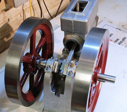
| Charles 2010 | 13/11/2010 17:44:46 |
84 forum posts 54 photos | more photos added ..
All the keyways cut and the flywheels set in position.
The engine has reasonable compression but I am wondering if the inlet valve spring is still too strong.
May be the exhaust sprng is not strong enough. All will be found out when I try to run the engine.
I still have the timing and ignition side of things to sort out as well as oil cups etc etc etc ... ... but hope to try to run it next Saturday 20 Nov for the first time.
 Regards Charles |
| ronnie barker | 14/11/2010 16:11:06 |
| 33 forum posts 8 photos | charles
you are making a lovely job of this engine but please dont fall into the trap and set your engine up to run correctly.
ive seen so many nicely built engines dont run as they should ie hit and miss, even the engine on L A services stand fires everytime , ive said to them about it with no reply.
keep up the good work
jonathan |
| Charles 2010 | 14/11/2010 18:43:49 |
84 forum posts 54 photos | What setting do you suggest Ronnie
I am a complete novice when it come to petrol engines ....
Anything you can help me with will be taken into consideration ...
I would like it to run as a hit and miss !!!!
So what are the secrets ???? |
Please login to post a reply.
Magazine Locator
Want the latest issue of Model Engineer or Model Engineers' Workshop? Use our magazine locator links to find your nearest stockist!
Sign up to our Newsletter
Sign up to our newsletter and get a free digital issue.
You can unsubscribe at anytime. View our privacy policy at www.mortons.co.uk/privacy
Latest Forum Posts
- hemingway ball turner
04/07/2025 14:40:26 - *Oct 2023: FORUM MIGRATION TIMELINE*
05/10/2023 07:57:11 - Making ER11 collet chuck
05/10/2023 07:56:24 - What did you do today? 2023
05/10/2023 07:25:01 - Orrery
05/10/2023 06:00:41 - Wera hand-tools
05/10/2023 05:47:07 - New member
05/10/2023 04:40:11 - Problems with external pot on at1 vfd
05/10/2023 00:06:32 - Drain plug
04/10/2023 23:36:17 - digi phase converter for 10 machines.....
04/10/2023 23:13:48 - More Latest Posts...
- View All Topics
Support Our Partners


Shopping Partners
Subscription Offer

Latest "For Sale" Ads
- Reeves** - Rebuilt Royal Scot by Martin Evans
by John Broughton
£300.00 - BRITANNIA 5" GAUGE James Perrier
by Jon Seabright 1
£2,500.00 - Drill Grinder - for restoration
by Nigel Graham 2
£0.00 - WARCO WM18 MILLING MACHINE
by Alex Chudley
£1,200.00 - MYFORD SUPER 7 LATHE
by Alex Chudley
£2,000.00 - More "For Sale" Ads...
Latest "Wanted" Ads
- D1-3 backplate
by Michael Horley
Price Not Specified - fixed steady for a Colchester bantam mark1 800
by George Jervis
Price Not Specified - lbsc pansy
by JACK SIDEBOTHAM
Price Not Specified - Pratt Burnerd multifit chuck key.
by Tim Riome
Price Not Specified - BANDSAW BLADE WELDER
by HUGH
Price Not Specified - More "Wanted" Ads...
Get In Touch!
Do you want to contact the Model Engineer and Model Engineers' Workshop team?
You can contact us by phone, mail or email about the magazines including becoming a contributor, submitting reader's letters or making queries about articles. You can also get in touch about this website, advertising or other general issues.
Click THIS LINK for full contact details.
For subscription issues please see THIS LINK.
Digital Back Issues


Donate

 Register
 Log-in
Model Engineer Magazine
- Percival Marshall
- M.E. History
- LittleLEC
- M.E. Clock

ME Workshop
- An Adcock
- & Shipley
- Horizontal
- Mill

Subscribe Now
- Great savings
- Delivered to your door

Pre-order your copy!
- Delivered to your doorstep!
- Free UK delivery!
All Forum Topics > I/C Engines > Scale model Economy hit & miss engine builders wanted