Forum sponsored by:

Home Made Rear Toolpost Issue
| Dr_GMJN | 07/03/2021 20:23:04 |
 1602 forum posts | Posted by Tony Pratt 1 on 07/03/2021 20:00:25:
A mild steel top plate will be fine, using cast iron on the original toolpost was bound to end in tears. Tony Doesn't bolting a top plate on, then having bolts through that to the tool, reduce stiffness? I could imagine the loads would be managed better if the top plate was acting directly in the top edge of the tool - less bending moment? Believe me I would love to be able to salvage this somehow, but if it's going to be another compromise/experiment....a Myford one is £50 new. If its a couple more hours with a slitting saw and a tap, then I'm up for it. Edited By Dr_GMJN on 07/03/2021 20:23:26 |
| old mart | 07/03/2021 20:32:24 |
| 4655 forum posts 304 photos | Most lathe saddles have a lock at the front which should be used when parting off. These locks usually clamp the saddle down to the bed. I added a rear lock to the Smart & Brown saddle for two reasons. The forces are upwards when using a rear parting tool. The bed of the lathe is very worn, and I added a rear lock to make sure the saddle was not lifted. There has to be some allowance for the saddle guides to have some clearance or the saddle would never reach the right end of the bed where there is no wear. |
| Dr_GMJN | 07/03/2021 20:34:44 |
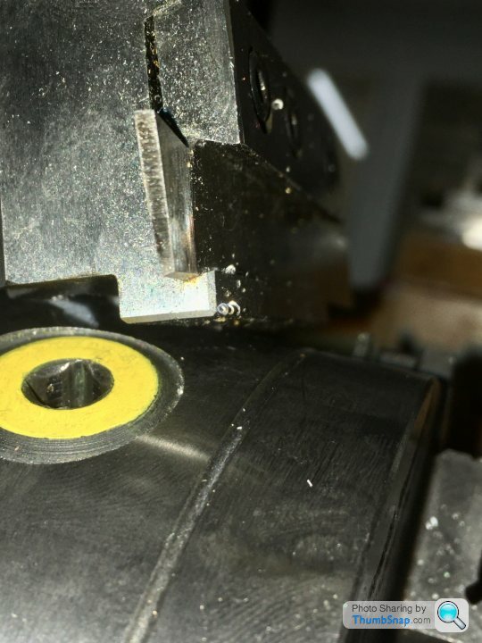
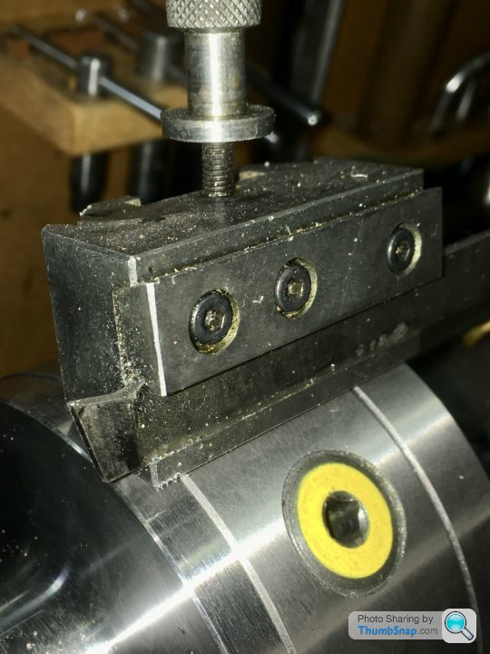
1602 forum posts | I've got this q/c blade holder that I don't think I've ever used. Could anything from this be salvaged to use on the cast iron thing? I noticed the lower groove is profiled, which is why I reject using the slot in the cast iron one - it's flat. I suppose I could angle a normal, small diameter, milling cutter to achieve the angle. The rest of the blade would be sitting against a flat face? |
| John Baron | 07/03/2021 20:37:55 |
 520 forum posts 194 photos | Posted by Dr_GMJN on 07/03/2021 18:06:11:
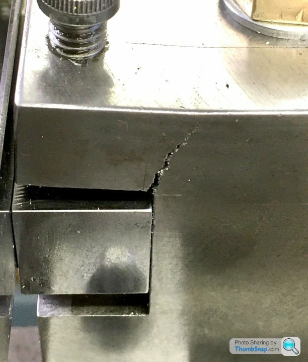
So I milled the key to clear the new bolt: Don't mess about ! Just break that lip off, mill a flat across the top and bolt a steel plate on there to replace the broken bit. That failure is about what you would expect from cast iron. Use a pair of M8 coarse threaded bolts. to fasten the new plate. Shouldn't take more than an hour !
Edited By John Baron on 07/03/2021 20:39:11 |
| Dr_GMJN | 07/03/2021 20:38:03 |
1602 forum posts | Posted by old mart on 07/03/2021 20:32:24:
Most lathe saddles have a lock at the front which should be used when parting off. These locks usually clamp the saddle down to the bed. I added a rear lock to the Smart & Brown saddle for two reasons. The forces are upwards when using a rear parting tool. The bed of the lathe is very worn, and I added a rear lock to make sure the saddle was not lifted. There has to be some allowance for the saddle guides to have some clearance or the saddle would never reach the right end of the bed where there is no wear.
My ML7 already has a rear saddle lock, that pulls the saddle down when engaged. I always use it when the saddle doesn't need moving during a cut. It's a bolt head, and I keep a ring spanner on it. I was going to get the Hemmingway kit for an indexable handle, but it's another job to do that's not making parts. Edited By Dr_GMJN on 07/03/2021 20:38:10 |
| Dr_GMJN | 07/03/2021 20:42:42 |
1602 forum posts | Posted by John Baron on 07/03/2021 20:37:55:
Posted by Dr_GMJN on 07/03/2021 18:06:11:
So I milled the key to clear the new bolt: Don't mess about ! Just break that lip off, mill a flat across the top and bolt a steel plate on there to replace the broken bit. That failure is about what you would expect from cast iron. Use a pair of M8 coarse threaded bolts. to fasten the new plate. Shouldn't take more than an hour !
Edited By John Baron on 07/03/2021 20:39:11
Won't that be a fairly flexible clamping method though? The bolts have to be offset for a reasonable distance in from the slot, so there's some prying load being applied when the lock bolts are tightened? Not saying it wont work, but if I'm going to salvage it, I'd rather have the maximum possible stiffness. That seems to be through the top edge being restrained, but I don't know how centre height is adjusted in that scenario. Thanks. |
| Maurice Taylor | 07/03/2021 20:58:05 |
| 275 forum posts 39 photos | Hi ,I adjust the center height on mine by fitting shims between toolpost and cross slide Maurice |
| John Baron | 07/03/2021 21:00:14 |
520 forum posts 194 photos | Hi Dr_GMJN, Just putting a steel plate on to replace the broken lip will not change the tool height or be any weaker than it would have been had it not failed. You could of course do a much better job which would require far more work for very little benefit ! What I've and I noticed other suggested the same would produce a quick and easy fix. Lets see piece of plate, five holes to drill four holes to tap. Two M8 two M6. Saw the top off, mill it clean, mark out for the five holes, drill. Tap the M6 holes, spot through the M8 ones. Drill 7 mm, thread the block M8. Fit the plate. Job done ! Opps forgot the hole for the long clamp screw.
Edited By John Baron on 07/03/2021 21:02:25 |
| Dr_GMJN | 07/03/2021 21:09:16 |
1602 forum posts | Ok thanks all. One way or another I'll retrieve it form the bin and give it one last go. Slot or top plate is the question. Top plate winning so far. I think I've got some plate that will do. |
| John Baron | 07/03/2021 21:25:41 |
520 forum posts 194 photos | Posted by Dr_GMJN on 07/03/2021 21:09:16:
Ok thanks all. One way or another I'll retrieve it form the bin and give it one last go. Slot or top plate is the question. Top plate winning so far. I think I've got some plate that will do. I think anything 3/8" inch or thicker will be quite satisfactory. Don't forget that the nut on top will also be adding to the security of the plate. For what its worth, and I'm sure you have seen the picture of mine, I use a cheap Chinese parting blade that is 2 mm thick, 12 mm wide and 200 mm long. It is perfectly rectangular in section. And is clamped by two screws with a third used to clamp the supporting piece. I don't have any packings or shims under the blade, the height of the whole tool block being used to set the blade centre height.
|
| Clive Brown 1 | 07/03/2021 21:46:07 |
| 1050 forum posts 56 photos | Posted by Dr_GMJN on 07/03/2021 20:17:08:
David, there is actually a slot machined in the other side: A suitable milling cutter is readily made from silver steel. Taper-turn the 14 deg. (IIRC) angle and mill two flutes. Nothing fancy. Here's the one I made years ago for my GHT rear toolpost. Cuts the angle a treat! |
| Dr_GMJN | 07/03/2021 21:54:06 |
1602 forum posts | Posted by Clive Brown 1 on 07/03/2021 21:46:07:
Posted by Dr_GMJN on 07/03/2021 20:17:08:
David, there is actually a slot machined in the other side: A suitable milling cutter is readily made from silver steel. Taper-turn the 14 deg. (IIRC) angle and mill two flutes. Nothing fancy. Here's the one I made years ago for my GHT rear toolpost. Cuts the angle a treat! Presumably heat treated - I did make a spot facing tool from silver steel last year which worked ok. So how do you adjust centre height with this type - pack the entire toolpost as suggested earlier, or is there a better method? |
| John Baron | 07/03/2021 22:04:35 |
520 forum posts 194 photos | Hi Dr_GMJN, Guys, You could make a holder for the blade that clamps into the slot in the tool block and use shims under it ! There is no way I would want to start shimming under the whole tool post.
|
| Dr_GMJN | 07/03/2021 22:21:02 |
1602 forum posts | The thing is...Years ago when I was given it - I drilled the Sandvik blade holder (god knows how), and bolted it to some steel, so I could use it in a quick-change holder. It's not the stiffest method, and there's always some spring between the end bolt and the end of the tool. Ideally I'd ditch the bolted connection altogether, and slide it into a slot directly milled in the cast iron.. That way, it's always held right to the end of the toolpost. Only problem is setting height. Edited By Dr_GMJN on 07/03/2021 22:21:10 |
| Dr_GMJN | 07/03/2021 22:25:40 |
1602 forum posts | Angled slot so that in-out movement gives a tip height change? Only good for one extension from the post though. |
| Howard Lewis | 08/03/2021 14:32:14 |
| 7227 forum posts 21 photos | My advice is to make the rear toolpost from Steel. (My one for the ML7 was 2 x 2 box section, with platforms welded into place. ) Cast iron is strong in compression, but as you now know, weak in tension. Remake your toolpost in steel and you should have no further problems. If you are worried about the Tee nut, you can make it longer, with the key only just deep enough to engage in the T slot, say 1/8". It only there to prevent the nut from rotating and if it is over an inch long, should do so without risking damage the Cross Slide. Similarly, the key on the bottom of the post can be shortened so that it does not clash with the key on the T nut. IN this way, the nut cannot rotate and the post is located along the full width of the post. OR Locate the post with a dowel, fitting the T slot closely, at each end of the post and have a long T nut in between. If you look in the album, at the underside of my toolpost base, you will see that it is located by a 1/4" dowel at each end, which bear on the rear face of the Cross Slide. Location of the post has never caused any problems in at least 17 years! If you want to ensure that the tool slot is square to the axis. Having machined the dowels holes, and fitted the dowels, and drilled the hole for the clamp bolt, Clamp the embryo post to the Cross Slide and flycut the front (Headstock ) face, before reversing and flycutting the rear face. The rear face can then be used as a datum to mill the slot for the parting tool, before drilling and tapping for the tool clamp screws.. Howard Edited By Howard Lewis on 08/03/2021 14:39:42 |
| Michael Gilligan | 08/03/2021 16:02:30 |
 23121 forum posts 1360 photos | With all the wise warnings about the properties of Cast Iron ... please do bear in mind what the ML7 tee-slots are made in. An inverted rear parting tool looks like a great idea [swarf drops out; and motor runs in the forward direction] but there is always that fragility to consider. MichaelG. [ gloom & doom merchant ] |
| Dr_GMJN | 08/03/2021 21:35:59 |
1602 forum posts | I found some M8 cap screws and a lump of steel plate about 15mm thick. Pretty much as suggested, I’ll chomp the top surface flat, and use 6x M8s (three adjacent to the now broken edge, three on the opposite side. I’ll d&t 4 M6s to hold the tool. I’ll keep my original Sandvik tool (because I got about 12 inserts with it), but make a steel clamping plate to spread the load of the securing bolts. If that doesn’t work I’ll part off using a hacksaw from then on. |
| Hopper | 08/03/2021 22:52:55 |
 7881 forum posts 397 photos | Posted by Dr_GMJN on 08/03/2021 21:35:59:
... If that doesn’t work I’ll part off using a hacksaw from then on. Actually Doc, for a lot of the model type stuff you are doing, you could do what I do and use a 5/16" x 1/16' HSS parting blade held in the front toolpost with normal forward spindle rotation direction. I use one of these on anything under about 3/4" diameter jobs and it works just fine. I only use the rear toolpost for lopping off sections of larger diameter bar etc. Edited By Hopper on 08/03/2021 22:53:31 |
| Hopper | 08/03/2021 23:00:44 |
7881 forum posts 397 photos | PS I found this type of 5/16 x 1/16 (or 8mm x 1.5mm) parting tool holder works better than the side mount types. Holds the blade more verttical and does not move. Its all I use for general parting of small jobs. Less faff than fitting the rear post.
|


Please login to post a reply.
Magazine Locator
Want the latest issue of Model Engineer or Model Engineers' Workshop? Use our magazine locator links to find your nearest stockist!
Sign up to our Newsletter
Sign up to our newsletter and get a free digital issue.
You can unsubscribe at anytime. View our privacy policy at www.mortons.co.uk/privacy
Latest Forum Posts
- hemingway ball turner
04/07/2025 14:40:26 - *Oct 2023: FORUM MIGRATION TIMELINE*
05/10/2023 07:57:11 - Making ER11 collet chuck
05/10/2023 07:56:24 - What did you do today? 2023
05/10/2023 07:25:01 - Orrery
05/10/2023 06:00:41 - Wera hand-tools
05/10/2023 05:47:07 - New member
05/10/2023 04:40:11 - Problems with external pot on at1 vfd
05/10/2023 00:06:32 - Drain plug
04/10/2023 23:36:17 - digi phase converter for 10 machines.....
04/10/2023 23:13:48 - More Latest Posts...
- View All Topics
Support Our Partners


Shopping Partners
Subscription Offer

Latest "For Sale" Ads
- Reeves** - Rebuilt Royal Scot by Martin Evans
by John Broughton
£300.00 - BRITANNIA 5" GAUGE James Perrier
by Jon Seabright 1
£2,500.00 - Drill Grinder - for restoration
by Nigel Graham 2
£0.00 - WARCO WM18 MILLING MACHINE
by Alex Chudley
£1,200.00 - MYFORD SUPER 7 LATHE
by Alex Chudley
£2,000.00 - More "For Sale" Ads...
Latest "Wanted" Ads
- D1-3 backplate
by Michael Horley
Price Not Specified - fixed steady for a Colchester bantam mark1 800
by George Jervis
Price Not Specified - lbsc pansy
by JACK SIDEBOTHAM
Price Not Specified - Pratt Burnerd multifit chuck key.
by Tim Riome
Price Not Specified - BANDSAW BLADE WELDER
by HUGH
Price Not Specified - More "Wanted" Ads...
Get In Touch!
Do you want to contact the Model Engineer and Model Engineers' Workshop team?
You can contact us by phone, mail or email about the magazines including becoming a contributor, submitting reader's letters or making queries about articles. You can also get in touch about this website, advertising or other general issues.
Click THIS LINK for full contact details.
For subscription issues please see THIS LINK.
Digital Back Issues


Donate

 Register
 Log-in
Model Engineer Magazine
- Percival Marshall
- M.E. History
- LittleLEC
- M.E. Clock

ME Workshop
- An Adcock
- & Shipley
- Horizontal
- Mill

Subscribe Now
- Great savings
- Delivered to your door

Pre-order your copy!
- Delivered to your doorstep!
- Free UK delivery!
All Forum Topics > Workshop Tools and Tooling > Home Made Rear Toolpost Issue