Forum sponsored by:

Further Adventures with the Sieg KX3 & KX1
A thread for new owners of these machines to post in.
| JasonB | 21/07/2019 17:09:19 |
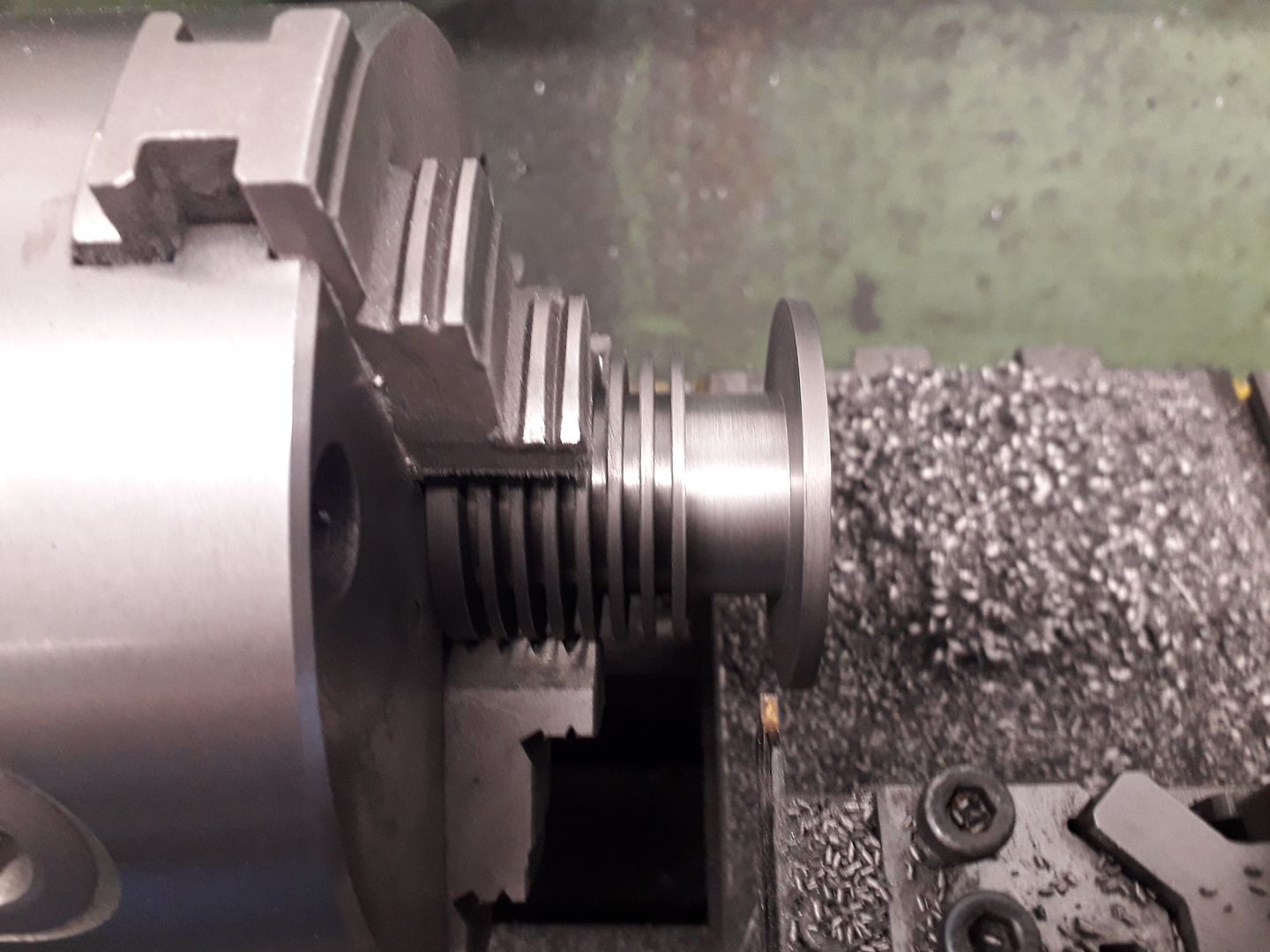
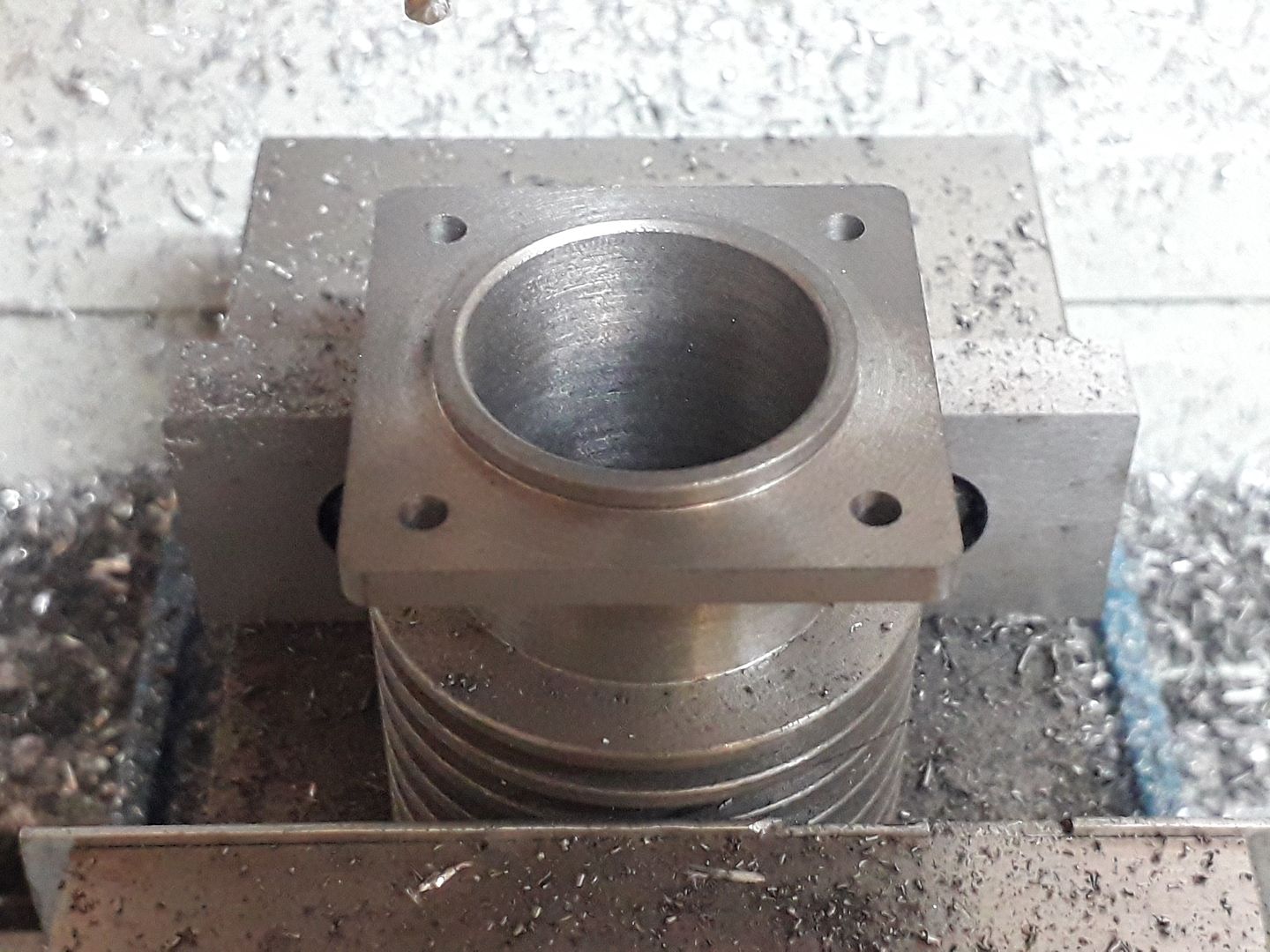
 25215 forum posts 3105 photos 1 articles | Nothing too exciting this weekend, just used the KX3 to profile and drill the cylinder flange for the Little Midget engine. If anyone wants to see the video then shout and I'll upload it. From this round flange
To this
J |
| Ron Laden | 21/07/2019 18:41:31 |
 2320 forum posts 452 photos | Posted by JasonB on 21/07/2019 17:09:19:
Nothing too exciting this weekend, just used the KX3 to profile and drill the cylinder flange for the Little Midget engine. If anyone wants to see the video then shout and I'll upload it. From this round flange
To this
J I would like to see the video if I may Jason |
| JasonB | 21/07/2019 19:29:02 |
25215 forum posts 3105 photos 1 articles | There's always one, here you go Ron Material Grey cast iron, 6mm 3-flute carbide cutter, 4000rpm, 300mm/min feed, 1mm OOC (0.6mm Finish cut). I just did a basic contour rather than a separate clearing cut first. |
| Ian Johnson 1 | 21/07/2019 20:01:33 |
| 381 forum posts 102 photos | There's always two! But I'm a bit slower than Ron! Nice video Jason |
| JasonB | 28/07/2019 10:42:44 |
25215 forum posts 3105 photos 1 articles | Another epic adventure for Ian & Ron. After a slight glitch with the latest Alibre update which was very promptly dealt with by their forum and support I was able to do the CAM for the cylinder head. The stock was roughed out on the lathe from some 50mm CI bar and two holes drilled and tapped where the valve holes will eventually be bored and used these to hold it to a block that could be held in the clamp. Video starts off with the adaptive clearing with 6mm 3-flute carbide, 4500rpm, 300mm/min feed. 5mm high cut x 1mm DOC. I set the CAM to cut in 5mm deep increments to use the edge of the tool and it then works back up in 1mm steps to cut to the final 0.5mm that is left for finishing. Bit of chatter from the tool when cutting conventionally but it's happier climb milling. tooling for the finish contour at the top of the valve guides as I wanted a sharp internal corner. Then onto the 3D contour using 6mm 4-flute R1 corner rounding carbide, 4750rpm, 400mm/min feed and 0.33mm stepdown, could have done finer on the more horizontal surfaces but happy to do a bit of file work to get that "cast look"
Pleased with the finish on the cast iron and I can recommend a CNC machine to all those who moan about cast iron being messy, I did not even get my hands dirty. It's about time that Neil stopped browsing through safety data sheets and got his KX1 up and running Edited By JasonB on 28/07/2019 10:48:28 |
| Ron Laden | 28/07/2019 16:32:15 |
2320 forum posts 452 photos | Nice job again Jason and yet another question, c,mon you know you would miss me if I didnt come along and have something to ask.. When programming do you have to enter every single movement of the tool, i.e. when it came off a cut and ran through a small circle and then moved back into cutting is all of that down to the programmer..? Ron
|
| JasonB | 28/07/2019 17:06:21 |
25215 forum posts 3105 photos 1 articles | Ron, that was one of the things that had put me off CNC in the past, all this talk of writing G-code and I also remember watching a couple of guys on the SMEE stand at an exhibition spend ages just trying to machine a simple flat surface that I could have done in a fraction of the time manually. However CAM has come to the rescue and will produce all the code for me. I do need to enter thing like type of tool and how fast I want it to run, DOC etc and one or two other things. It is then a question of deciding on the type of operation and just clicking on the overall shape for things like the contour or the holes for drilling and even then I can just click one and tick a box so it selects all holes of the same size. There are several other tweaks that can be used to suit the part in hand but it works out all the paths from the info entered. There is an extensive tool library with preset speeds and feed for various materials, so just select a tool and adjust the parameters to suit which can be saved There are six basic operations to form that part 1. 3D adaptive clearing. This roughing cut removes the bulk and leaves 0.5mm for later finishing 2. 2D contour . Finish cut around the tops of the two valve guides 3. 3D contour this refines the overall curved shape in shallow steps 4. Horizontal contour which finishes the flat horizontal areas of the flange and skims the top of the valve guides 5. 2D Vertical contour which finishes the vertical faces of the oval flanges each side 6. Drilling Probably took me 1/4hr to do the Cam but would be far less if I knew what I was doing then click a button and the machine spits out just less than 29,000 lines of G-code. Other facts you may be interested in is that the cutters travelled a total of 29.18m and removed 65.1% of the original block in 1min 14sec. Edited By JasonB on 28/07/2019 17:08:08 |
| Ron Laden | 28/07/2019 19:15:14 |
2320 forum posts 452 photos | Thanks Jason, impressive the way it works and also the information it gives at the end of the job. |
| Ian Skeldon 2 | 28/07/2019 19:36:19 |
| 543 forum posts 54 photos | Fantastic to watch Jason, thanks for sharing. If I had the knowledge to back it up then a cnc mill would certainly be on the cards, am I right in thinking it makes the rotary table almost obsolete? |
| John Haine | 28/07/2019 19:44:19 |
| 5563 forum posts 322 photos | Almost? Totally! |
| JasonB | 28/07/2019 19:55:56 |
25215 forum posts 3105 photos 1 articles | With a 3 axis machine like I have then the CNC will do just about all a Rotary Table can when it is in the horizontal position but I would still need it for things like cutting gears or drilling radial holes when in the vertical position so would not be getting rid of it If the machine had a 4th axis then the rotary table would gather some dust assuming it was not used as the basis for the 4th axis by fitting a stepper motor to it. Edited By JasonB on 28/07/2019 19:57:10 |
| Old School | 13/08/2019 10:24:48 |
| 426 forum posts 40 photos | I am finally starting to get the hang of Fusion 360 and my KX1
This is the first project it is an adaptor plate for a 2.5cc tether car engine to fit a Zimmerman disk induction system instead of the drum valve induction apparently faster the one at the top is the original one that has stripped threads the blue one a practice run and the one on right the last attempt. Just a little more work to do on it the the big holes have a 3mm countersunk screw it them with a head diameter of 4mm, just waiting for a spot drill to arrive to put the countersink in. |
| Old School | 13/08/2019 10:37:05 |
| 426 forum posts 40 photos | With this initial success I have moved on to making some pistons for 1.5cc Kapu tether car engines. The pistons are made from high silicon content aluminium, its nice to machine but wears the tools out quickly.
I make the piston blanks double ended so you can use the other end to hold it while machining. The gudgeon pin holes also go in at this stage.
All set up on the machine and milling under way.
The pistons all hollowed out maching time just over 4 minutes each at lot quicker than doing by hand on my milling machine and the are all the same. The final operation is to turn them to fit the to the refurbished liners. |
| Former Member | 13/08/2019 10:43:33 |
[This posting has been removed] | |
| JasonB | 13/08/2019 13:32:52 |
25215 forum posts 3105 photos 1 articles | Good to see another one of these machines putting out some work which looks to have turned out well. |
| Emgee | 13/08/2019 14:10:53 |
| 2610 forum posts 312 photos | Posted by Old School on 13/08/2019 10:37:05:
With this initial success I have moved on to making some pistons for 1.5cc Kapu tether car engines. The pistons are made from high silicon content aluminium, its nice to machine but wears the tools out quickly. The final operation is to turn them to fit the to the refurbished liners.
Search for some PCD inserts, some may cost £30 each inc post but they are available at £10 for 2 delivered from some sellers, those from China may not be the same quality as the more expensive but I find they are super inserts for high silicon and all tougher aluminium alloys and give super finish even when using fine finishing cuts. Emgee Edited By Emgee on 13/08/2019 14:12:28 |
| Old School | 13/08/2019 15:10:37 |
| 426 forum posts 40 photos | Thanks Emgee thanks what I use for the final turning to size, the cuts you can take are tiny you can see the tiny bits of metal coming off the piston in the cutting fluid. Its the £30 ones that I use not worth using cheap tools on a lot of time and expensive material.
Barrie 5 of the piston already have new homes in Sweden and Switzerland just got to fit them to the liners, the rest are for my son Aaron Next race is in Basel over the bank holiday weekend followed closely by one in Poland. Going to miss the nats this year. |
| Ian Johnson 1 | 13/08/2019 18:13:36 |
| 381 forum posts 102 photos | Posted by Old School on 13/08/2019 10:37:05:
The pistons all hollowed out maching time just over 4 minutes each at lot quicker than doing by hand on my milling machine and the are all the same. The final operation is to turn them to fit the to the refurbished liners. The KX1 did a really nice job machining the inside of the pistons. This is what CNC is all about! My KX1 has been idle for a while, it needs to do some work! Ian |
| JasonB | 17/08/2019 20:31:21 |
25215 forum posts 3105 photos 1 articles | next part for the Midget engine that could be done on the CNC were the rocker arms which were cut on the opposite ends of a bit of 1.5" x 0.25" flat steel bar. First a clearing cut all round with 6mm 3-flute cutter at full depth plus 1.1mm to give the later 1mm R corner mill clearance, this then rises up and roughs out the top contour in 0.5mm steps. Followed by a 4mm dia 4-flute 1mm R corner cutter working it's way down in 0.2mm steps on the flatter surfaces then 1mm as it gets to the vertical. Side shot of the work so far. Then a shot after it was sawn off the bar and held in machined jaws to bring down to 5mm thickness in the X3 Then back with the 4mm bit to contour the other side again held in the machined jaws Finished parts after a lick with a needle file. |
| JasonB | 21/08/2019 16:11:37 |
25215 forum posts 3105 photos 1 articles | While others prefer to discuss the shape of their heads I found a bit of time to run the CAM for some cams. In the past I would either have used CamCalc with multiple offsets of the mill at angular increments around the cam or used the inside out boring head method particularly on cams like this with a flank radius. Both of which take a while to setup and in the CamCalc case a long while to cut. This time with 0.4mm deep x 5.5mm high roughing passes and a slightly slower fed 0.2mm DOC finish pass on the silver steel the cam was done in 2.30mins with no need to do any blending with files after. I can't see me wanting to go back the the old ways of doing things.
Edited By JasonB on 21/08/2019 16:42:17 |


Please login to post a reply.
Magazine Locator
Want the latest issue of Model Engineer or Model Engineers' Workshop? Use our magazine locator links to find your nearest stockist!
Sign up to our Newsletter
Sign up to our newsletter and get a free digital issue.
You can unsubscribe at anytime. View our privacy policy at www.mortons.co.uk/privacy
Latest Forum Posts
- *Oct 2023: FORUM MIGRATION TIMELINE*
05/10/2023 07:57:11 - Making ER11 collet chuck
05/10/2023 07:56:24 - What did you do today? 2023
05/10/2023 07:25:01 - Orrery
05/10/2023 06:00:41 - Wera hand-tools
05/10/2023 05:47:07 - New member
05/10/2023 04:40:11 - Problems with external pot on at1 vfd
05/10/2023 00:06:32 - Drain plug
04/10/2023 23:36:17 - digi phase converter for 10 machines.....
04/10/2023 23:13:48 - Winter Storage Of Locomotives
04/10/2023 21:02:11 - More Latest Posts...
- View All Topics
Support Our Partners


Shopping Partners
Subscription Offer

Latest "For Sale" Ads
- Reeves** - Rebuilt Royal Scot by Martin Evans
by John Broughton
£300.00 - BRITANNIA 5" GAUGE James Perrier
by Jon Seabright 1
£2,500.00 - Drill Grinder - for restoration
by Nigel Graham 2
£0.00 - WARCO WM18 MILLING MACHINE
by Alex Chudley
£1,200.00 - MYFORD SUPER 7 LATHE
by Alex Chudley
£2,000.00 - More "For Sale" Ads...
Latest "Wanted" Ads
- D1-3 backplate
by Michael Horley
Price Not Specified - fixed steady for a Colchester bantam mark1 800
by George Jervis
Price Not Specified - lbsc pansy
by JACK SIDEBOTHAM
Price Not Specified - Pratt Burnerd multifit chuck key.
by Tim Riome
Price Not Specified - BANDSAW BLADE WELDER
by HUGH
Price Not Specified - More "Wanted" Ads...
Get In Touch!
Do you want to contact the Model Engineer and Model Engineers' Workshop team?
You can contact us by phone, mail or email about the magazines including becoming a contributor, submitting reader's letters or making queries about articles. You can also get in touch about this website, advertising or other general issues.
Click THIS LINK for full contact details.
For subscription issues please see THIS LINK.
Digital Back Issues


Donate

 Register
 Log-in
Model Engineer Magazine
- Percival Marshall
- M.E. History
- LittleLEC
- M.E. Clock

ME Workshop
- An Adcock
- & Shipley
- Horizontal
- Mill

Subscribe Now
- Great savings
- Delivered to your door

Pre-order your copy!
- Delivered to your doorstep!
- Free UK delivery!
All Forum Topics > CNC machines, Home builds, Conversions, ELS, automation, software, etc tools > Further Adventures with the Sieg KX3 & KX1