Forum sponsored by:

Stuart victoria
Piston stroke
| Arthur Goodwin | 07/02/2021 19:42:20 |
| 71 forum posts 45 photos | Hi all
WOW what a response. I dont know who to answer first. Apologies for late reply had a family crisis today which diverted me. Jason. I bought the kit and drawings together. Not from Stuarts but of a colleague who had purchased them years before from Stuarts and everything was sealed up in the original box. Re the main bearing I set it equal equal on the pad to accommodate the 1.5 inch centres, Have got the book for building but was very aware of dimesion mismatch and always adhered to main drawing which coincidently doesnt have a number. just a statement that says it supercedes al pre 1993 drawings Tug have took on board all your observations and will work thro them tomo. Phoning stuarts tomo so will give you an update then.
Thanks to all
Arthur
|
| Former Member | 07/02/2021 19:54:17 |
| 1085 forum posts | [This posting has been removed] |
| Arthur Goodwin | 08/02/2021 11:45:26 |
| 71 forum posts 45 photos | Hello Spoke to Stuarts this morning and they confirmed I should have had the errata sheet in with my kit and the con rod crnters ate correct at 6 and 5/32. Also the piston rod lenght at 3 and 1/32 from x head center to back of piston. The one good thing to come out of it was he iffered to replace the con rod material and also waived the p&p. Thanks to all for your input. My next post hopefully will be a working engine. Regards Arthur |
| Arthur Goodwin | 08/02/2021 12:03:43 |
| 71 forum posts 45 photos | Hello Spoke to Stuarts this morning and they confirmed I should have had the errata sheet in with my kit and the con rod crnters ate correct at 6 and 5/32. Also the piston rod lenght at 3 and 1/32 from x head center to back of piston. The one good thing to come out of it was he iffered to replace the con rod material and also waived the p&p. Thanks to all for your input. My next post hopefully will be a working engine. Regards Arthur |
| JasonB | 08/02/2021 13:32:33 |
 25215 forum posts 3105 photos 1 articles | Thanks for the update Arthur and keep us posted on progress. As for me getting hold of some castings to measure and draw up all I will say for now is watch this |
| Former Member | 08/02/2021 13:37:58 |
| 1085 forum posts | [This posting has been removed] |
| Ramon Wilson | 08/02/2021 13:40:34 |
 1655 forum posts 617 photos | Glad to hear you're on your way to sorting things out Arthur - and yes, do keep us informed of progress. Jason - you must have a silver tongue if you mean what I think you mean All's well that ends well - keep on smiling everyone - bit too much snow for my liking here at the moment.
Regards - Tug |
| Andy_C | 08/02/2021 13:48:43 |
| 66 forum posts 13 photos | Arthur, don’t miss the dimension changes on the sole plate which are consistent with those of con rod and piston rod. |
| JasonB | 08/02/2021 14:39:06 |
25215 forum posts 3105 photos 1 articles | I think Ramon and myself feel the soleplate can stay as is but the new conrod should be made to a dimension taken from the work that has been done so far. As I said earlier measure from centre of the guide bars to centre of the crankshaft and make this the length of the conrod for THIS ENGINE. I might suggest cutting a bit of stiff card and making suitable holes in it as a test conrod to double check things are lining up OK before you cut into the replacement metal, crosshead should move 1" either side of guide bar ctr when crank is at TDC and BDC Ramon, you are not thinking quite right but it will be a bit more than just a loan |
| Former Member | 08/02/2021 14:39:49 |
| 1085 forum posts | [This posting has been removed] |
| Nigel McBurney 1 | 08/02/2021 14:48:33 |
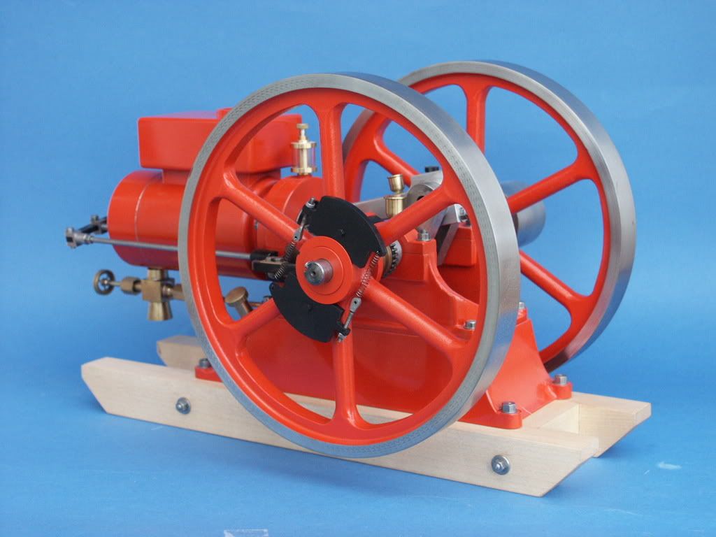
 1101 forum posts 3 photos | Looking at the Stuart flywheel on this engine and some others in their range,I cannot see any reason why at the outer end of each spoke there is an odd shapped lump where the spoke meets the rim,never seen anything like this in full size practice,any ideas as to why. |
| JasonB | 08/02/2021 15:17:27 |
25215 forum posts 3105 photos 1 articles | I think they have only got the one pattern now and the odd shapes are for when you bolt two together for the twin victoria. Even then the bumps are best removed from the outer edges and left where they tough in the middle. Unlike me most other people don't remove the odd bits when using the single flywheel and leave then on the finished engine, it's not hard to turn off most of them while turning the flywheel and then a bit of Dremel work will take care of the rest Two Stuart flywheels with the offending lumps removed
Edited By JasonB on 08/02/2021 15:21:20 |
| Former Member | 08/02/2021 15:25:49 |
| 1085 forum posts | [This posting has been removed] |
| JasonB | 08/02/2021 15:42:26 |
25215 forum posts 3105 photos 1 articles | It may just have been from an older casting Bill, I know when I built my beam back in the early 80s that it did not have the bumps cast in. |
| Former Member | 08/02/2021 15:50:14 |
| 1085 forum posts | [This posting has been removed] |
| Howard Lewis | 08/02/2021 16:05:10 |
| 7227 forum posts 21 photos | Ignoring, for the moment, the various Design Changes to components, and working from basics.. ASSUMING that the cylinder centreline is the same height from the bedplate as the Crankshaft centreline, the piston stroke will be twice the throw of the crankshaft ( [Crankpin center to Crankshaft centre] x 2 ) To allow the engine to rotate, the distance between the standards for the Slide Bars must be greater than the Stroke. This difference will be twice the design clearance between Crosshead and Slide Bar standards. The Con Rod Centres should be Crank Pin Centre to Gudgeon Pin centre, with the Cross Head clear of the Slide bar Standards by the designed Crosshead to Standard clearance, at Inner and Outer Dead Centres. The Piston Rod length should be such that at Inner or Outer Dead Centre, the Centre of the Gudgeon Pin bore just provides the clearance at each end of the cylinder. Some designs might attempt to cater for the difference in effective Piston area, on each side, by allowing more clearance on the Piston Head side than on the Rod side. The rights and wrongs of this approach should not enter into this discussion, unless the basic design dimensions suggests that this is the case here. Far easier, (but theoretically wrong, perhaps ), to aim for equal clearance at both ends. Having taken some dimensions, it should be possible to find the dimensions for Con Rod Centres, and Piston Rod length, for THAT particular engine, which may differ from the dimension shown on a drawing, especially if the drawings are at different Design Change levels. HTH Howard |
| Ramon Wilson | 08/02/2021 17:25:27 |
1655 forum posts 617 photos |
Posted by Howard Lewis on 08/02/2021 16:05:10:
Ignoring, for the moment, the various Design Changes to components, and working from basics...... .... Having taken some dimensions, it should be possible to find the dimensions for Con Rod Centres, and Piston Rod length, for THAT particular engine, which may differ from the dimension shown on a drawing, especially if the drawings are at different Design Change levels. Well I never Howard - who would have thought it could be so fundamentally straight forward Sorry Howard - could stop myself Best regards - Ramon (Tug) |
| Howard Lewis | 09/02/2021 18:06:16 |
| 7227 forum posts 21 photos | Well Tug, There has been a lot of toing and froing about the dimensions on drawings, which seem to take little account of what mixture of parts are actually in THIS particular engine. The lack of errata for the drawings (ie documenting Design Changes ) is NO help, and may well account for the problems. I have seen a LOT of Design Changes and keeping all the parts compatible can be quite daunting. I have come across some right hybrids; Bolts with A/F heads and Whitworth threads was one, liable to result in damage to one or other of the mating parts. An engine that failed despite everything being correct to drawing; until it was pointed out that two parts of an assembly have moved relative to each other!. Hence my suggestion to start measuring to find out what dimensions the parts should be. The problem really seems to be to arrive at a set of components that actually allow THIS particular engine to function. If all else fails, go back to first principles. Fine tuning can vastly improve function Howard |
| Former Member | 09/02/2021 18:20:59 |
| 1085 forum posts | [This posting has been removed] |
| JasonB | 09/02/2021 18:32:43 |
25215 forum posts 3105 photos 1 articles | Howard. I think Ramon's comment was based on the fact we have been saying to make the piston rod and conrod length to suit what has been built for the last 3 pages of this thread. The discussion of drawing is to try and see where the error may have come from in the first place so that others can avoid the same problem.. Even with the correction sheets I have found errors that they don't seem to cover, anyone able to make this to the sizes shown?
Edited By JasonB on 09/02/2021 18:38:01 |

Please login to post a reply.
Magazine Locator
Want the latest issue of Model Engineer or Model Engineers' Workshop? Use our magazine locator links to find your nearest stockist!
Sign up to our Newsletter
Sign up to our newsletter and get a free digital issue.
You can unsubscribe at anytime. View our privacy policy at www.mortons.co.uk/privacy
Latest Forum Posts
- hemingway ball turner
04/07/2025 14:40:26 - *Oct 2023: FORUM MIGRATION TIMELINE*
05/10/2023 07:57:11 - Making ER11 collet chuck
05/10/2023 07:56:24 - What did you do today? 2023
05/10/2023 07:25:01 - Orrery
05/10/2023 06:00:41 - Wera hand-tools
05/10/2023 05:47:07 - New member
05/10/2023 04:40:11 - Problems with external pot on at1 vfd
05/10/2023 00:06:32 - Drain plug
04/10/2023 23:36:17 - digi phase converter for 10 machines.....
04/10/2023 23:13:48 - More Latest Posts...
- View All Topics
Support Our Partners


Shopping Partners
Subscription Offer

Latest "For Sale" Ads
- Reeves** - Rebuilt Royal Scot by Martin Evans
by John Broughton
£300.00 - BRITANNIA 5" GAUGE James Perrier
by Jon Seabright 1
£2,500.00 - Drill Grinder - for restoration
by Nigel Graham 2
£0.00 - WARCO WM18 MILLING MACHINE
by Alex Chudley
£1,200.00 - MYFORD SUPER 7 LATHE
by Alex Chudley
£2,000.00 - More "For Sale" Ads...
Latest "Wanted" Ads
- D1-3 backplate
by Michael Horley
Price Not Specified - fixed steady for a Colchester bantam mark1 800
by George Jervis
Price Not Specified - lbsc pansy
by JACK SIDEBOTHAM
Price Not Specified - Pratt Burnerd multifit chuck key.
by Tim Riome
Price Not Specified - BANDSAW BLADE WELDER
by HUGH
Price Not Specified - More "Wanted" Ads...
Get In Touch!
Do you want to contact the Model Engineer and Model Engineers' Workshop team?
You can contact us by phone, mail or email about the magazines including becoming a contributor, submitting reader's letters or making queries about articles. You can also get in touch about this website, advertising or other general issues.
Click THIS LINK for full contact details.
For subscription issues please see THIS LINK.
Digital Back Issues


Donate

 Register
 Log-in
Model Engineer Magazine
- Percival Marshall
- M.E. History
- LittleLEC
- M.E. Clock

ME Workshop
- An Adcock
- & Shipley
- Horizontal
- Mill

Subscribe Now
- Great savings
- Delivered to your door

Pre-order your copy!
- Delivered to your doorstep!
- Free UK delivery!
All Forum Topics > General Questions > Stuart victoria