Forum sponsored by:

Steam Engine Number One
A Build Log (hopefully)
| Iain Downs | 05/02/2019 07:36:57 |
| 976 forum posts 805 photos | Dennis, Jason. Thanks for the advice on the ER32. It would seem that my foray into engineering merely reveals an increasing vista of ignorance - soothed only by the knowledge and advice on this forum. And thanks for the advice on drilling, Jason. Very obvious once you're told! I have a 15mm blacksmith's drill on order. The only thing that surprised me is the size of the starter drill. I would have thought that a 6mm would be quite slow and to get through the solid metal. What sort of speed should I run this at? I tend to be cautious on speeds (fear and ignorance).
Iain |
| JasonB | 05/02/2019 07:53:59 |
 25215 forum posts 3105 photos 1 articles | I'd probably be at 8-900 rpm for the 6mm. Drop to say 600rpm for the 10mm and around 300 for your 15mm. Should not be a problem getting into the metal with a 6mm provided it is sharp. |
| Iain Downs | 16/02/2019 17:07:40 |
| 976 forum posts 805 photos | So after a few weeks of distraction (and to be honest, the shed being far too cold to face), I've finally 'finished' the crankshaft.
All that's left is to pin the crank and the cut out the awkward bit of the shaft.
Drilling the pin holes (to 3.9mm)
Then reaming
The metal for the pins was source from a specialist retailer - B&Q! I have no idea what sort of steel it is.
However, before using them I performed extensive malleability. That is I hit the rods with a hammer and made short the dented and spread. Precision engineering at it's finest. Which was carried through in the delicate insertion and fixing of said pins.
The 'anvil' was a small piece of inch plate sourced from a scrapyard. I wasn't terribly good at this bouncing around somewhat. Which (I'm claiming0 is why some of the pins bent and stuck and I had to push the other half in from the other side. Curiously, I found that despite being assembled on a surface plate with some care and being glued good and proper the journals are not (any more?) totally in line (about 0.25mm out from one end to the other). I'm rather hoping that the shafts are in line! Next cut out the middle bit
I used the mill to take the bulk of the left over material ( one or two mm) and then finished with a file. Tada! A Crankshaft.
Iain |
| Iain Downs | 16/02/2019 17:20:41 |
| 976 forum posts 805 photos | And not content with finishing the crank, I immediately started up on the cylinder. I mounted it on the lathe in a four jaw and centred it on the markings I'd set in a previous job.
I must say that seeing that enormous chunk of iron on what is a fairly small lathe was a bit daunting. I'm slightly worried about it handling a 50mm bore through the length without shifting. For today, however, the task was to cut out the flange at one end of the block. This I could do with a centre adding some support, though the sheer size required me to cut a wierd shaped tool so that I could physically get to the material in the right place (and still provide access to the centre and tailstock.
There's a depressing thought here about how much cast iron dust I will be making in the next phases. More than half the volume. Do you think I can sell it back to the supplier? I'm afraid I'm going to have to ignore Jason's (most excellent) advice on drill speeds. If I were to run this at 800 rpm, the lathe would walk out the door - probably over my dead body! I can get it up to a bit under 300 rpm before the vibration gets too much. the work above was done at around 200 rpm with fine cuts (0.25mm) and a very gentle feed. Any more than that risked stalling and a jam and release set it of ricking back and fore in a most disturbing way. For the benefit of anyone as innocent as I, the cut is very much an interrupted cut on quite a large diameter (for a tiny lathe), so each rotation there is s significant change of load as it goes from not cutting to cutting. Poor lathe. Still we've survived. Next is to drill out to as big as I can go (14mm I think) and then gently bore out another 36 mm - gently!. Iain
|
| Iain Downs | 21/02/2019 17:37:46 |
| 976 forum posts 805 photos | OK a bit more done. Following my Sage (Jason), I've drilled a bit with 6mm then 10mm then more with 6mm and so on until through. Then a push through with a Blacksmiths drill.
On thing which I saw here is that the drills seemed to swing up and away as it entered deeper into the hole. This particularly with 6mm as the 10mm filled the space. I don't know if this is just the torque pulling it out of centre or if the tailstock is contributing to this. I have measure the tailstock as about 0.25mm higher than the headstock on a test bar and with a 2MT just this week found that the bar points upwards from the tailstock by about 0.1mm in 100 mm. Having a good sort out of the tailstock is on my todo list (bolstered by a purchase at Doncaster 2 years ago of a lapping plate I've not used!). But it's going to need a bit of girding of loin cloths to get the courage to start it! Next was to bore out. FIrst with a smallish carbide boring bar and then with the hss indexable boring bard seen in earlier posts.
and here's my boring bar. My first attempt at a tool bit wasn't very good and it needed careful alignment so as not to scrape in the early stages.
But, dear God, this is going to take a long time! The raised part is more or less where the cylinder bore should be. Number one skill for model engineers? Manual dexterity? no. technical drawing skills? No. Mathematical insight? No. Patience?
Iain |
| Iain Downs | 24/02/2019 18:47:38 |
| 976 forum posts 805 photos | After spending a goodly amount of time watching my hard earned pennies turning into cast iron dust, I've finally got the bore through the cylinder.
As best I can tell I've managed to bore this to exactly 50.00 mm. I'm measuring the bore with (Aldi) digital calipers and I'm confident neither in their accuracy nor in my ability to use them with this precision. Still.... One thing I realised after i'd started the whole process off was that the bore was wider than the gap left by the 4 jaw chuck. Accordingly the last 3 or 4 mm were not bored all the way through. This isn't a crisis as I need to take a bit off the end anyway. At least I hope it's not a crisis. The next step is to turn it round, reduce to the right length and cut the other end flange. As I have only a 5mm ridge to grip onto (with an 85mm long chunk of metal) I felt that I should secure this better. The idea is to have a disk which I can clamp through the central bore. Not having anything particularly appropriate, I took a 50mm square aluminium bar cut a bit off the end (my chop saw does not like me now) and trimmed it. I can remove and trim off the what's left once the challenging intermittent cuts on the outside are complete. I hope.
Note, regular readers, that I managed to insert the collect correctly in the holder this time! And here it is sort of complete.
I was going to carry on, but my lathe appeared to develop asthma. It wheezed and grunted and refused to get up to speed. I could stop the spindle with moderate finger pressure. Since, I've left it to cool down (though it's not been working hard) and went back an hour later and it seems OK. I may well be begging for help on this in the forum, but I'll make that a separate post.
Iain |
| Iain Downs | 09/03/2019 16:20:36 |
| 976 forum posts 805 photos | We left the last post with our intrepid hero concerned that he might have broken his lathe. He had. It would seem that the interrupted cut was too interrupted (or the hero too brutal?) and the sacrificial motor pulley had duly thrown itself on the alter of sacrifice. I did give some thought to printing a new one, but given that (in theory) the pulley was designed to break the internal key and not the motor, I wasn't sure that it would have quite the same shear characteristics. So out came the chequebook (metaphorically) and £6.50 worse off I got a replacement (I got two actually - one way of making sure things break is not to have a replacement). With that I set to and finished of the lathing part of the cylinder. As the cylinder was now held less securely in the chuck (just the 5mm of the flange) I wanted to make sure that it was held in place hence a rod through the headstock pulling it against the chuck. As you see below.
Once I'd got the outside trimmed down I could finish of the end proper with out the bolt.
So the 'finished' product...
The cylinder is about 0.25mm too short. This is due to something that happened just before the finishing cut when the cross-head seemed to jump forward for no apparent reason. Clearly this was something I did, but I really don't know what. Perhaps I nudged the dial with an elbow. A bit annoyed at that as I was creeping up on the exact length (to the various limits of my ability and measuring devices). However, it's not going to stop it working. Now all I need to is remove 2/3rds of the remaining metal on the mill. Shouldn't take too long on my CMD10.... Iain |
| Paul Kemp | 09/03/2019 23:58:10 |
| 798 forum posts 27 photos | I love this thread for a number of reasons; it's something different, not too serious, not seeking the last tenth of a thou, using machines to their 'full' capacity....... Great, well done, keep it up. Paul. |
| Iain Downs | 10/03/2019 16:18:11 |
| 976 forum posts 805 photos | Hmm. Describes me to a T. Not too serious, terribly inaccurate and overambitious with projects... But many thanks indeed, Paul. Iain |
| Iain Downs | 11/03/2019 16:08:52 |
| 976 forum posts 805 photos | The benefit of unemployment is that it gives me a bit more of a chance to create cast iron dust and I duly managed this today. One hopes to keep working on the Steam Engine, but the wife wants me in a job. Sigh... About my first book on engineering was one the Mr Hall's books. This one on milling. In it the first thing he says is that the main challenge in milling is working out how to hold the workpiece. I'd agree with that, and it took quite some puzzling to work out how to hold the partial cylinder accurately with the thick piece uppermost. One of the things I realised is that it didn't much matter if I got the exact thickest part uppermost provided that I could get a wide enough cut for the valve face. So this is what I came up with.
The ally bar is to raise it a bit (for assembly, then removed). The two Stevenson's blocks are clamped to cylinder ends which are (I hope) normal to the bore. Finally, the rotation is checked with the T square - you can just see the scribed line if you put your good glasses on! Next to mount it on the mill
The reason for raising the piece is mainly so that i can get the indicator at (more or less) centre height. Finally, the drudgery of slicing of the top at 1mm doc at a time. With a 3 flute carbide mill that goes quite nicely albeit slowly.
So next up is to square off the sides. I', trying to work if I should cut the valve ports on the top now, whilst It's in place or if I should wait until I've thinned down the outside. I'm also seriously wondering how I'm going to mount it on my 4 inch rotary table. On the rather small worktable. I was hoping to (somehow) use my Christmas present tailstock, but that really won'f fit. I suppose the good news is that I really am just throwing the outside away so there's no particular need for high accuracy. Iain |
| Gas_mantle. | 19/03/2019 20:38:00 |
 359 forum posts 269 photos | Hi Iain, I've just seen your thread and it looks like you are making great progress, I was recommended to read about your build as I want to build something of a similar size as a horizontal engine. I haven't read through the thread in it's entirety yet but it looks to be an interesting one to follow. My hope is to try to cut a large cylinder about 60mm bore from a 85mm cast iron square bar, I wasn't sure it it was practical on a hobby machine but it looks like my lathe and mill are similar a similar size to yours. I look forward to an update on your progress. |
| Iain Downs | 19/03/2019 21:04:29 |
| 976 forum posts 805 photos | So continues my drive to discard the large part of a perfectly good cast iron cylinder. In the previous post I'd machined the top of the valve port. Next was the sides. I did this in steps of about 10mm with a 1mm DOC.
And the finished block (for now, probably needs a bit of tidying once the rest of the bar is removed.
Next: How on EARTH am I going to mount this vast chunk of metal on a rotary table on my tiny mill?
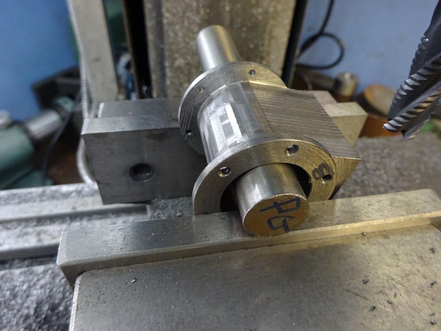
That's the general idea. A chuck is impractical for a number of reasons. One of which is that by the time I have a decent sized chuck on there and mount the cylinder, the cylinder would be off the edge of the table! Another is that I did not think that the 5mm flange would provide enough grip. Boy was I right about that! (more on that later). In the end I decided to use an MT2 blank, a clyindrical spacer and a clamp on the top. This gives and idea
The MT2 blank (drilled and tapped to M10 is held in by a 10mm bolt, the cylinder fits snugly on the spacer cylinder and another M10 bolt clamps the top of the cylinder - as below. As seems usual, I'd underestimated the spring in the boring bar and ended up cutting the inside a bit too much making it rattle somewhat. However, a 0.15 shim (feeler gauge) slipped around the blank fixed that nicely!
You can see why a normal chuck just wouldn't work! Also in view is my Heath Robinson mill end stop. A couple of clamps bolted down and nice little vertical rod on the Y axis to act as a stop. I said above that the other reason that I couldn't mount it on a chuck is the lack of grip. There is a LOT of vibration when removing the outside of the cylinder. The Z creeps up, the handles fall off and the X can shift too (so I need one hand to hold the X axis, one to hold the z axis and one to turn the wheel - hang on....!) What's more challenging is that it's actually shifting the rotary table on the mill table, even after adding stops and clamps to it. In fact that's where I gave up today. I have to work out how to hold it in place more rigidly. Or I could revert to taking very small cuts but this is already taking forever! A mill and a rotary table will NEVER replace a lathe...
Iain |
| Iain Downs | 19/03/2019 21:19:34 |
| 976 forum posts 805 photos | HI Gas Mantle. I'm delighted if this thread is interesting to you! The only thought I had was to ask you about the cylinder design. With a 50mm bore, 5mm wall thickness and a 10mm flange (which is what I have) plus the valve face I needed a 100mm bar to get it all in.
Iain |
| Gas_mantle. | 19/03/2019 21:31:11 |
359 forum posts 269 photos | Hi Iain, I have most of the materials and the flywheel casting so I'm committed to starting it soon but haven't yet finalised how I'm going to cut the cylinder and so haven't yet bought the stock for it. Last year I made a little entablature engine using the technique Jason explained for the cylinder earlier in this thread. I thought I could just about squeeze a 60mm bore from an 85mm square with care but I may need to look again at the maths. The bore I'm aiming for is approx 60mm and about 80mm stroke but if it ends up at 55mm then that isn't a problem. Peter
|
| JasonB | 20/03/2019 07:13:38 |
25215 forum posts 3105 photos 1 articles | Iain, I would try and add some support to the other end of the cylinder such as an angle plate or even a bit of angle iron would do and should fit if the leg of the "L" faces towards the rotary table. You could also rough out a lot of the waste with the cylinder between two angle plates/irons just turning a few degrees at a time and then back onto the R/T for the final rounding cuts which would be a lot more solid. The two 45degree roughing cuts on this cylinder were done like that but you could do say every 10degrees or so just rotating by eye.
The two angles effectively become the jaws of a vice and if you rest your two flanges on some packing that will set a constant height.
Also think about getting a roughing cutter and rather than feeding down 1mm at a time use more of the side once you are to depth something like this. The rougher will reduce the load on the machine and you will be using more of the cutting edge rather than just blunt the bottom 1mm. |
| Gas_mantle. | 24/03/2019 18:39:48 |
359 forum posts 269 photos | Hi Iain, I've been thinking what you said about cutting a large cylinder from solid, this engine on ebay is similar to what I was hoping to achieve from square stock
Edited By Gas_mantle. on 24/03/2019 18:41:02 Edited By Gas_mantle. on 24/03/2019 18:46:00 Edited By Gas_mantle. on 24/03/2019 18:50:29 |
| Iain Downs | 03/04/2019 19:19:50 |
| 976 forum posts 805 photos | Hi, Gas_Mantle. I'm afraid I couldn't work out how the vents channels worked from the picture in that page. I suggest that you need to find (or make) a drawing of what you want to do and ask for advice. I suggest you start a new post which may attract more responses than if it's just embedded in this thread! Good luck!
Iain |
| Iain Downs | 03/04/2019 19:48:51 |
| 976 forum posts 805 photos | There've been a few sessions in the workshop since my last post, but I've not had a chance to post them up. I found I'd gone a bit too far to follow some of Jason's advice. I already had a cylinder of sorts so roughing out at 45 degrees didn't seem like it was worthwhile. However, the idea of taking a deeper cut to use more of the mill struck me as eminently sensible.
Despite this being sensible, it proved a little too much for the poor mill - to be more accurate my 3D printer! IN an earlier episode, the motor drive gear had give up the ghost and I'd replaced it with a 3D printed one, which has supported my endeavours tidily through the past few months. However, this was too much for it.
Poor thing. I did attempt to superglue it back together, but this lasted but moments. As the shattering of the gear resulted in the key (conductive) ricocheting round the box which contained the motor controller (electric!) I decided that prudence was the order of the day and reached out to ARC for spares. Why not print another one you ask? Well I didn't but it was not a good print. I think my printer needs some maintenance - I find them temperamental things. Usual excellent service from ARC and a couple of days later I had the cogs, but other things got in the way and I only returned to the task today. Because I had to leave some metal for drain taps, I'd decided to carve out the cylinder 8mm short of the end flanges and then separately carve out the remaining 8mm (apart from the tap mounts) with a snub ended mill. I'm told that one should try and avoid sharp edges! My first snub nose use...
And finally, the finished product!
To finish this off, I need to mill out the valve ports, lap the valve face and drill the end cap mounting holes. I might leave that for a while and get started on the big connecting rod assembly. Which means back to the drawing board as I need to finish of some changes. In a spirit of masochism (for a Yorkshireman), I weighted the part. A tad over 1Kg. which means I've flushed away 90% of the cast iron I paid for! That hurts...
Iain .
|
| Iain Downs | 10/05/2019 12:31:58 |
| 976 forum posts 805 photos | To those of my devoted followers who have been wondering what I've been doing for the lat month, the answer is, 'not a lot'. Not of taking perfectly good metal away from a part. Most of that is professional domestic, however, I have been a bit stuck on the cross head guide for my engine. If you recall I had not realised that such was necessary so hadn't considered it. Geoff walker and Jason B help me to understand about the tubey type of guide and of course I think I'd already seen the squarer, slidey type of guide (most used in horizontals). This seemed complicated so I got on with making the bits I did understand (more or less!). Now, however, I'm at the point of making the con rod assembly so it's become important. The thing that I'm trying to work out is which is the easiest to fabricate with the least precision required. The slidey type guide I think would be easiest in a horizontal, but with an open column engine (I think it's called) I would struggle to find somewhere to put it and it spoils my artistic idea of tapering the columns. It's a lot of pieces (or a lot of machining), but I guess it could be done. The tubey type thing actually looks more doable, though there's an uncomfortable amount of accurate concentric lathing to do. It is also probably more aesthetic given the type of engine. With a stroke of 60mm I have a throw of 30mm. The big end rod is designed at 120mm (2 * stroke). According to my excel calculations (checked roughly in my CAD package), that means that the maximum excursion at the bottom of where the tube needs to be is about 16 mm (at a bit over 65 degrees from TDC). Add half the diameter of the con rod (13mm dia) and the internal bore of the tubey thing needs to be 32+13 = 45mm.
So I'd need a tubey thing with an internal bore of 45 - 50mm. One of the reasons for going into this dull detail is that Mr Ballamy suggested that a tubey thing (page one of this epic) with an external diameter of 25mm and an internal of 18mm would be a good start. I expect this was just a wild arsed guess, but I tend to treat his wild arsed guesses with a bit more seriousness than my careful plans, so wanted a sanity check. Ray Hasbrouk's Engine number one has been one of my inspirations and that has a tubey thing made from 2 inch iron pipe which sounds close to my calculations. I don't know where to get 2 inch pipe (in 6 inch lengths!) and have an aversion to buying 50mm round bar and taking away 90% of it. So I throw myself on the mercy of the expertise. Is buying a bit of rod and exercising my best boring bar the best way or should I try and rethink the design - perhaps even go for a slidey thing. For what it's worth, this is the outline of the engine design as it stands at the moment, without adding crosshead support.
Any advice provided today will allow me to buy parts in Doncaster tomorrow. No pressure
Oh - and one attempt at the big end bearing went badly wrong as I tried to mill it to width. Something slipped and one side ended up 5mm lower than the other - and too low. So I've re-ordered a bit of cast and reduced it with the lathe which has worked better. I'm hoping to get close to finishing that today. As usual, my thanks in advance.
Iain
|
| JasonB | 10/05/2019 14:46:20 |
25215 forum posts 3105 photos 1 articles | yes my 1" guide wa sa bit small given the size of your engine. I have just looked at my Todman which is 76mm stroke, 140mm conrod and has 41.25mm between the guides. based on that you should be able to get something around the 38-40mm internal diameter. Did a rough sketch of your engine frame, scaled my conrod and crank down to your sizes and sketched out a quick trunk guide (tube thing) with a 40mm bore, 4mm wall. If you stick with a parallel 13mm rod you will need the small 1mm x 2mm chamfer for clearance but if you belly the rod as shown then you could omit the chamfer. Or keep the chamfer and reduce bore to 38mm. Cross head will just pop out the bottom of the guide but that will save wearing any ridges. Edited By JasonB on 10/05/2019 14:47:40 |


 .
.Please login to post a reply.
Magazine Locator
Want the latest issue of Model Engineer or Model Engineers' Workshop? Use our magazine locator links to find your nearest stockist!
Sign up to our Newsletter
Sign up to our newsletter and get a free digital issue.
You can unsubscribe at anytime. View our privacy policy at www.mortons.co.uk/privacy
Latest Forum Posts
- hemingway ball turner
04/07/2025 14:40:26 - *Oct 2023: FORUM MIGRATION TIMELINE*
05/10/2023 07:57:11 - Making ER11 collet chuck
05/10/2023 07:56:24 - What did you do today? 2023
05/10/2023 07:25:01 - Orrery
05/10/2023 06:00:41 - Wera hand-tools
05/10/2023 05:47:07 - New member
05/10/2023 04:40:11 - Problems with external pot on at1 vfd
05/10/2023 00:06:32 - Drain plug
04/10/2023 23:36:17 - digi phase converter for 10 machines.....
04/10/2023 23:13:48 - More Latest Posts...
- View All Topics
Support Our Partners


Shopping Partners
Subscription Offer

Latest "For Sale" Ads
- Reeves** - Rebuilt Royal Scot by Martin Evans
by John Broughton
£300.00 - BRITANNIA 5" GAUGE James Perrier
by Jon Seabright 1
£2,500.00 - Drill Grinder - for restoration
by Nigel Graham 2
£0.00 - WARCO WM18 MILLING MACHINE
by Alex Chudley
£1,200.00 - MYFORD SUPER 7 LATHE
by Alex Chudley
£2,000.00 - More "For Sale" Ads...
Latest "Wanted" Ads
- D1-3 backplate
by Michael Horley
Price Not Specified - fixed steady for a Colchester bantam mark1 800
by George Jervis
Price Not Specified - lbsc pansy
by JACK SIDEBOTHAM
Price Not Specified - Pratt Burnerd multifit chuck key.
by Tim Riome
Price Not Specified - BANDSAW BLADE WELDER
by HUGH
Price Not Specified - More "Wanted" Ads...
Get In Touch!
Do you want to contact the Model Engineer and Model Engineers' Workshop team?
You can contact us by phone, mail or email about the magazines including becoming a contributor, submitting reader's letters or making queries about articles. You can also get in touch about this website, advertising or other general issues.
Click THIS LINK for full contact details.
For subscription issues please see THIS LINK.
Digital Back Issues


Donate

 Register
 Log-in
Model Engineer Magazine
- Percival Marshall
- M.E. History
- LittleLEC
- M.E. Clock

ME Workshop
- An Adcock
- & Shipley
- Horizontal
- Mill

Subscribe Now
- Great savings
- Delivered to your door

Pre-order your copy!
- Delivered to your doorstep!
- Free UK delivery!
All Forum Topics > Stationary engines > Steam Engine Number One