Forum sponsored by:

Stuart Twin Victoria (Princess Royal) Mill Engine
| Dr_GMJN | 10/08/2022 17:25:35 |
 1602 forum posts | I drew it to scale as well, and I wouldn't call it marginal. In fact with a 1:100 taper (nominal 1/8" thick), length my interpretation as "to suit" (as per the instructions), you get all the shear area of a parallel key - represented by the dashed line): |
| Ramon Wilson | 10/08/2022 18:28:27 |
 1655 forum posts 617 photos | No Doc nor would I, but your original drawing was. However short of knocking on the flywheel (and off) with the key already in the slot which of course one can do so easily when it's in your hand that is very unlikely full size - which is what I thought you wanted to try to replicate. My apologies for this misunderstanding. I have found some old photographs this afternoon taken at the Science and Technology museum in Manchester. I can't scan them but I can take an image so will do so later. there are several details that may be of help. |
| Paul Kemp | 11/08/2022 00:40:33 |
| 798 forum posts 27 photos | Posted by JasonB on 10/08/2022 11:19:05:
Ramon this should show what I meant by "head end" the grub screw is towards the head of the key so will only add further tilting force, had it been at the narrow end of the key it may have counteracted and tilt induced by the key.
I think our thoughts are basically the same, For what the Doc can do with his kit: Single keyway in the shaft which I would have with stopped ends not extending beyond largest dia. Single parallel keyway in flywheel as it's easy to cut Parallel key with a head for looks which will provide the drive. Small M3 grub screw at each end of this slot to take up any slack in the fit of the flywheel on the shaft and also stop the flywheel moving along the shaft. Screws to bear on key so you don't chew up the shaft Optional additional keys and keyways for looks only is desired
Edited By JasonB on 10/08/2022 11:25:11 The key to this conundrum is as Jason’s last drawing above if you are fixed on a parallel keyway in the flywheel. Do as Jason indicates with a parallel key and keyways and two small grub screws, that removes any risk of tilt and the angle of the screws oppose each other so it should never move. The second option is do it as per full size with a tapered key and keyway using a broach and suitable tapered bush. Again if the tapers match and a bit of careful filing will ensure that, whack it in and again it’s not moving. On some of the other comments; I must be missing something as I went back to the first drawing and it didn’t suggest to me the key would be short. A key drives on the flanks, not the top and I was always taught a parallel key should have top clearance (I have fitted a few on propellers and couplings etc over the years and no one has ever complained it broke or fell off). As stated by Jason a tapered key in a parallel keyway will always come loose. Finally no one mentioned the modern engineer’s friend - loctite!!!! No grub screws required. The key or keys can be any shape you like. For me the second option would be the way to go (broaching will let your lathe breathe a sigh of relief) but it’s not my engine and not my lathe. All the best, Paul. |
| Ramon Wilson | 11/08/2022 08:23:02 |
1655 forum posts 617 photos | No one in the right mind would use Loctite to fix a flywheel in place. Loctite has its right place in engineering but this is not one of them - That would make the flywheel and crankshaft a one piece item to my mind. Whilst not an actual issue it's just not a direction someone making a representation of a full size engine should consider to my mind. Once it's on it's on and IF it needs to be tweaked there's no chance. I may not have made many engines by some counts but I have made enough to know that the option of taking things apart is one definitely required on any build. By comparison to most the the Twin Vic flywheel is wide - without seeing the mating part in relation ship there is no indication of length of the key as shown in the original drawing I was merely trying to point out that short tapered keys may not provide the drive in the long term if fitted in the intended way - from one end of an open slot. I cannot think of a single example where a part is assembled to a headed key fitted within a closed slot. No doubt there will be someone with evidence to the contrary but it just doesn't make sense to me based on what I have seen over the years. As always it's down to choice - I know what I would do and fitting a headed key into a closed slot is not one of them If the intent is to make something as close to full size is there then why not do it and fit the keys in the proper way as already said grub screws are a compromise.
Edited By Ramon Wilson on 11/08/2022 08:24:00 |
| Ramon Wilson | 11/08/2022 08:53:25 |
1655 forum posts 617 photos | Paul, If my last post came across as a bit short it wasn't intended to be - my apologies. Having reread your post I went back over my own - this is from my first reply to the original one raising 'keys' three pages back If you cut the keyway parallel and you can slightly taper the key by careful filing until it tightens in the right spot but it will only be on the high point of course. A parallel key with a tiny grub screw is much the better option - the key does the driving, the screw just enough to keep it in place laterally. On that note I shall say no more - on this matter
Best - Ramon Edited By Ramon Wilson on 11/08/2022 08:54:06 |
| Martin Connelly | 11/08/2022 10:43:56 |
 2549 forum posts 235 photos | I have been following this section on the use of tapered keys. There is some discussion regarding a tapered keyway in the flywheel but no one has put forward the possibility of putting a tapered keyway into the shaft. I would think that a tapered keyway in the shaft is a relatively simple option compared to cutting a tapered keyway with a tapered bushing down a hole. Having had discussions in the past (not on this forum) with a designer regarding keyways and keys on tapered joints I see no problem with a tapered slot in the shaft. The keyway slots I ended up doing in the tapered hole and shaft were both parallel to the axis of rotation but were not parallel to the line of contact of the two parts. As Jason or Dr_GMJN pointed out earlier the relevant shear section of the key is not changed by its orientation, parallelism or taper. I would use my 5" sine bar with a 0.05" gauge block to set up to cut both the key and the shaft keyway to a 1:100 taper. Martin C Edited By Martin Connelly on 11/08/2022 10:47:36 |
| Paul Kemp | 11/08/2022 20:33:17 |
| 798 forum posts 27 photos | Ramon, lol, I am afraid it was my rather obtuse sense of humour. I was just surprised given the frequency loctite and similar products get suggested on here that no one had chipped in with the familiar cry “loctite” so I thought I would cast the line! For the record I wouldn’t seriously consider it for this application either but do bear in mind that there are various grades of the stuff and it’s not necessarily for ever as some can be separated by application of relatively mild heat. Quoting you “No one in the right mind would use Loctite to fix a flywheel in place. Loctite has its right place in engineering but this is not one of them - That would make the flywheel and crankshaft a one piece item to my mind. Whilst not an actual issue it's just not a direction someone making a representation of a full size engine should consider to my mind. Once it's on it's on and IF it needs to be tweaked there's no chance.” If someone is making a representation of a full size engine though why not use the techniques used on the full size? Is a grub screw or two more heretic than a blob of loctite? Neither mirror the prototype On the closed keyway / gib head key issue I have seen that done on line shaft pulleys but by and large I would agree with you this is not a very common way to fit that type of key. Martin, I don’t see any issue at all in reversing the taper and applying it to the shaft, should be exactly the same effect. Paul. |
| Ramon Wilson | 11/08/2022 23:31:55 |
1655 forum posts 617 photos | I was a bit too quick to condemn there Paul as I'm a confirmed Loctite user on the right application so yes, on a twin crank web shaft such as this once the cranks are set in place the flywheel (unless it's two halves) isn't going very far but, tongue in cheek aside, I still wouldn't advocate it I've studied a fair number of stationary engines over the years not to mention images but cannot recall ever seeing a sunken gib headed key on a flywheel - unless the slot is open ended. Whatever, Doc G has more than enough to make a decision on but here are a few images that may help, not only on flywheels but other areas too You can only just see the staked keys on this gorgeous McNaught Corliss valved engine in the Science & Industry (not Technology as previously said) museum in Manchester
This is the flywheel on the Galloways piston drop valve cross compound engine at the same place
A main bearing on another cross compound in the Kew Bridge museum. Built by Simpson it has an identical twin which was situated in the Strumpshaw St. Eng. Museum in Norfolk. Note the centre in the shaft, no key in the crank web and thin nuts on top plus other details.
And another main out rig bearing, more in keeping with Doc's intentions on the Hick and Hargreaves Corliss valved engine in Forncett. Note the typical variation in nuts on a renovated museum exhibit
With regard to the actual machining a slot or keyway. Like most matters there's a huge variation on the manner in which to achieve either. Regrettably however, most are not conducive with doing it on an ML7 with limited kit - to my mind that is the major factor to be taken into consideration before offering advice that the recipient would find difficult if not extremely unlikely to be able to put into practice.
Best for now - Ramon
|
| Hopper | 12/08/2022 05:46:14 |
 7881 forum posts 397 photos | However, if one did want to cut a tapered keyway in a flywheel bore in a Myford, various of the old books by Sparey and Mason and others show various simple set ups to use the topslide as a slotter by taking out the feedscrew and using a long handlever that is pivoted on a column bolted further back on the cross slide and attached to the topslide. It works like a hand shaper by yanking the end of the lever back and forth. By setting the topslide at an angle, a tapered keyway could be cut. Lot of mucking around though. |
| Hopper | 12/08/2022 11:40:29 |
7881 forum posts 397 photos | Posted by Roderick Jenkins on 12/12/2017 15:32:32:
This one was made by the previous owner of my lathe. I believe it is the Mason design as mentioned above. It works very well. HTH, Rod From another thread. Illustrates my garbled description above. I must get around to making on. Handy for graduating dials etc too with a couple of depth stops. |
| Dr_GMJN | 21/08/2022 19:31:56 |
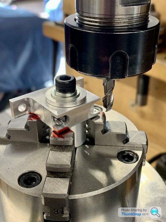
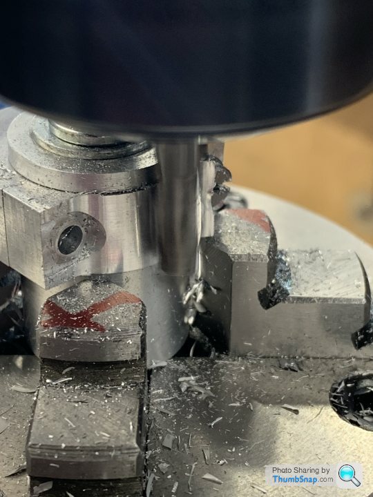
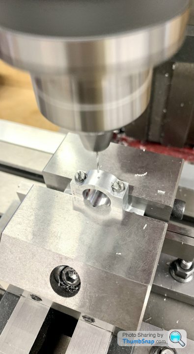
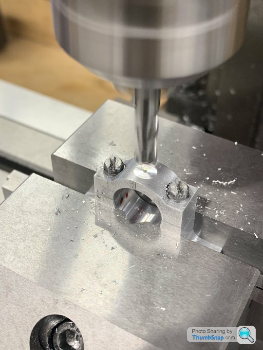
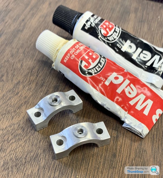
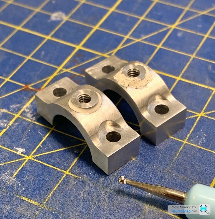
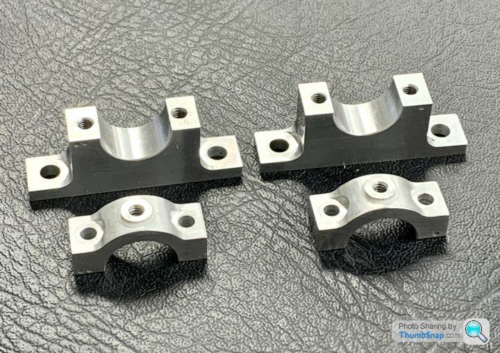
1602 forum posts | Continued with the housings, a repeat of the previous process with a few minor tweaks for the additional radii: |
| Dr_GMJN | 24/08/2022 22:22:13 |
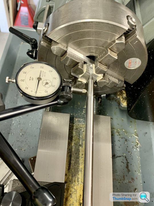
1602 forum posts | So regarding the crankshaft. Following Ramon's advice, I had a go at grinding an HSS tool. It's not pretty: |
| Ramon Wilson | 24/08/2022 23:50:19 |
1655 forum posts 617 photos | Doc, The edge faces of the tool need a reasonable back rake, the top rake is about 2-3 degrees, 5 at most, and there's no side rake on the top surface but you could put a little on if you are only cutting on the left hand side of the tool - mine has none so it cuts in both directions. Going right into a corner with all in contact puts a lot of cutting pressure on which quickly leads to chatter if the tool is not really sharp and the head stock a tad worn etc. Try coming up to the corner in several cuts inwards gradually creating the full form - that will improve things considerably. You do not need to undercut the shaft at all but set the leading edge of the cutter square to the shaft and let the tool create a radius. If you haven't got a dead stop for the saddle then create one by clamping a piece of bar on the bed and coming up to it for depth. Make a simple gauge for the amount of movement required to set the stop bar position. A method of stopping the saddle at a fixed position is a facility well worth having - once you have it you will quickly realise that. I use mine all the time using slip gauges to set the movement but as said a simple gauge can be quickly made. Personally I would not machine the centres off in case you need to remount it between centres. EG to polish a tight spot. Use the smallest centre drill and by all means face the ends to leave a small diameter cone if desired - once you remove them you've lost that ability to set it up again - your choice, but if you do face them off and you do require to remount it you will soon see exactly why I'm saying that. Make the initial shaft to finished length plus a tiny amount for facing and use packing as you say to prevent the carrier from doing any damage.
Best - R Edited By Ramon Wilson on 24/08/2022 23:54:11 |
| Paul Kemp | 25/08/2022 00:00:18 |
| 798 forum posts 27 photos | If I were making that I would rough out the steps with the raw bar in the chuck at the same time as putting the centres in, hold on the largest diameter in chuck, face, centre, rough out steps and reverse to do the other end leaving diameters say 0.5mm oversize and lengths maybe 1mm depending on the width of the undercuts desired. Set up between centres, finish turn centre and stepped diameters. Grind a tool like a parting tool but with a radiused nose for the undercuts, working from the end kiss the step with the tool, measure the length with the vernier from the end, use the top slide (set parallel with bed) to advance the tool the required amount and put the undercut in, repeat for second and third measuring always the total length from the end (saves tolerance build up) Reverse the shaft, set your dog on shim as you suggest and repeat for other end. However I would be leaving the centres in so you will need to add an allowance to machine them off after. Paul. |
| JasonB | 25/08/2022 07:09:06 |
 25215 forum posts 3105 photos 1 articles | If using that HSS tool I would also rotate the toolpost so that you are presenting the left cutting edge of the tool almost at right angles to the lathe axis but with a bit of clearance. Infact just like your carbide tooling does. That way you can also use it for facing a shoulder square and if fed in a little deeper than the diameter cut it will also do your undercut. As you have the tool at the moment you get a lot of contact along teh cutting edges and that is going to cause chatter, angled only the radius of the end will be cutting. I'm sure I have seem picture sof Ramon's tool mounted like this, he may be able to post one if not I'll dust off the HSS and take one. Rather than turn the smallest diameter first which leaves a big step get some ctr support and do the long length upto the central section this will mean that when you get to the step the edge of the tool won't be taking such a deep cut which will reduce the chance if chatter. Then do the next smallest dia and so on all will end with shallow steps. I don't have a DRO on my lathe and unlike the myfords the carriage handwheel is insensative and marked in 0.020" increments. I tend to set my topslide parallel to the lathe axis and it's handwheel dial to set a final cut which is then applied with the cross slide
Edited By JasonB on 25/08/2022 07:14:26 Edited By JasonB on 25/08/2022 07:17:56 |
| Dr_GMJN | 25/08/2022 07:38:01 |
1602 forum posts | Thanks all. What about using an HSS parting tool, ground with a radius, then do the undercuts to final depth (after roughing to the largest o/d? Then work on the diameters knowing that the tool will run into the groove and the lengths are already correct? Ramon - I made a saddle stop a while ago, but probably don’t use it as much as I should. My saddle hand wheel is a bit sloppy, and if using power feed it’s easy to strain the drive when it hits the stop if I do t release the feed at precisely the right time. Jason - so for the long central length, how do you get an accurate length? Not sure my top slide has the range (will have to check). Do you check for top slide x-alignment with a dti? Mine can turn and just had an angle scale on it with two clamp bolts. So potentially all the careful setup of the tailstock to turn parallel could be negated by using the top slide unless it’s set perfectly parallel. Edited By Dr_GMJN on 25/08/2022 07:38:45 |
| JasonB | 25/08/2022 07:42:28 |
25215 forum posts 3105 photos 1 articles | Measure from the end. You can use the "third option" on a digital calliper against the shoulder to get a good measurement of where you are and just put on the final amount with the topslide
|
| JasonB | 25/08/2022 08:36:41 |
25215 forum posts 3105 photos 1 articles | Topslide is set with a dti BUT it is only used to advance the tool towards the the headstock to put on a cut or two which faces the shoulder to final distance from the end. Not used to turn the diameter that is done with carriage and power feed. |
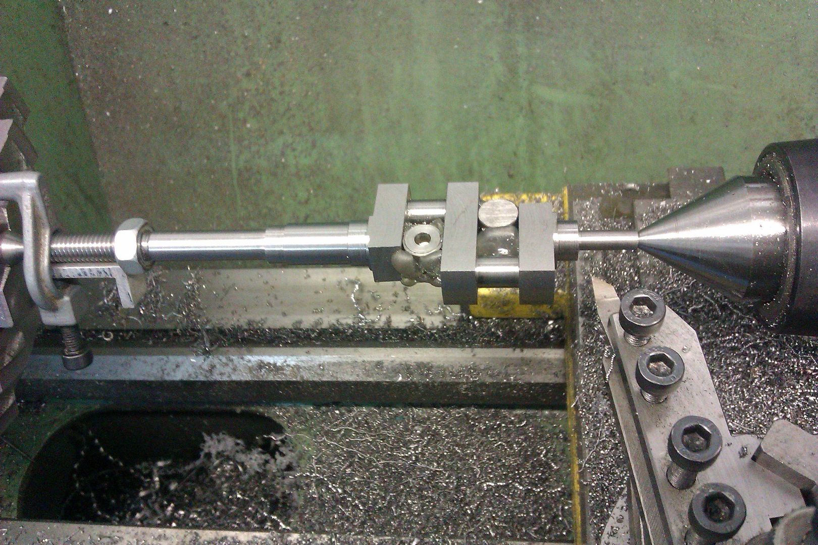
| Ramon Wilson | 25/08/2022 08:51:47 |
1655 forum posts 617 photos | Doc, I don't use the top slide for turning unless I'm turning a taper and certainly would not use it to turn parallel - just too much effort to get it set right only to lose it as soon as it needs moving. You can soon get bogged down in how to set the TS dead parallel which for this operation simply isn't required but, advice is what it is, you do the choosing. I can't recall my ML7 but setting the topslide parallel interferes with the tailstock on the Super 7 when turning between centres giving restricted movement on the cross slide. My top slide is permanently set at 15 degrees for that very reason and only gets moved to change the angle if required There really is no need to undercut the shaft, there's no justification for doing so besides it's not full size practice. The tool you have ground is fine - you may just need to tweak it a bit to improve the cutting - part of the learning process in grinding tools by hand. Here's a short version of the one I posted previously roughing out the crankshaft for the Corliss engine - virtually the same as your shaft just larger
It was finished with the other, longer, tool shown previously. Note the radii - an undercut would be considered to reduce a crankshaft to a thinner diameter for absolutely no practical reason
If you have a dead stop then use it in this case. Carefully face a small length(s) of steel to the dimension(s) required and set the stop. With one hand on the hand wheel lift the self act lever a little before the stop is reached and finish off the last few thou by hand. A dead stop is not designed for running into under power! As Jason I have no DRO on the lathe - doing the above provides an accurate method by simple means. As always though the advice is based bearing in mind on what kit you have and how I would tackle it as such. You do the choosing
Best R |
| JasonB | 25/08/2022 10:14:08 |
25215 forum posts 3105 photos 1 articles | Yes does come down to what you have, the big extended handwheel that some fit to a Myford will give a better feel as can having a 0.001" graduated scale. Having neither I turn most with power feed and then face the shoulder back using the topslide scale. I do have one of the extended holders for the Dickson post which allows the topslide to be parallel when using HSS and the tailstock or a DC** holder will reach in a standard holder. This pick also shows how I would angle the tool so it can square up any shoulders as well as turn diameters at one tool position.
As Ramon says it is not usual to undercut a shaft like this but I can see why the article suggested it and would likely do it myself if using the tool you have ground. The step down in diameters is only 1mm per step, that is going to leave a shoulder of only 0.5mm, now given that the HSS tool looks like it may have a 0.75mm tip radius you are not going to get a flat face to the steps. Add to that any deburring of the mating parts and they are not going to locate along the shaft with any exactness Only way is to do the undercut the depth of which will be governed by the dia of the tool. Easy to see that the "shoulder" on the left would not give very positive location but the one on the right gives a flat shoulder and provided you only deburr the mating part lightly will give a positive lengthways location to the part
Edited By JasonB on 25/08/2022 10:15:50 |


.jpg")
.jpg")
.jpg")
.jpg")

Please login to post a reply.
Magazine Locator
Want the latest issue of Model Engineer or Model Engineers' Workshop? Use our magazine locator links to find your nearest stockist!
Sign up to our Newsletter
Sign up to our newsletter and get a free digital issue.
You can unsubscribe at anytime. View our privacy policy at www.mortons.co.uk/privacy
Latest Forum Posts
- hemingway ball turner
04/07/2025 14:40:26 - *Oct 2023: FORUM MIGRATION TIMELINE*
05/10/2023 07:57:11 - Making ER11 collet chuck
05/10/2023 07:56:24 - What did you do today? 2023
05/10/2023 07:25:01 - Orrery
05/10/2023 06:00:41 - Wera hand-tools
05/10/2023 05:47:07 - New member
05/10/2023 04:40:11 - Problems with external pot on at1 vfd
05/10/2023 00:06:32 - Drain plug
04/10/2023 23:36:17 - digi phase converter for 10 machines.....
04/10/2023 23:13:48 - More Latest Posts...
- View All Topics
Support Our Partners


Shopping Partners
Subscription Offer

Latest "For Sale" Ads
- Reeves** - Rebuilt Royal Scot by Martin Evans
by John Broughton
£300.00 - BRITANNIA 5" GAUGE James Perrier
by Jon Seabright 1
£2,500.00 - Drill Grinder - for restoration
by Nigel Graham 2
£0.00 - WARCO WM18 MILLING MACHINE
by Alex Chudley
£1,200.00 - MYFORD SUPER 7 LATHE
by Alex Chudley
£2,000.00 - More "For Sale" Ads...
Latest "Wanted" Ads
- D1-3 backplate
by Michael Horley
Price Not Specified - fixed steady for a Colchester bantam mark1 800
by George Jervis
Price Not Specified - lbsc pansy
by JACK SIDEBOTHAM
Price Not Specified - Pratt Burnerd multifit chuck key.
by Tim Riome
Price Not Specified - BANDSAW BLADE WELDER
by HUGH
Price Not Specified - More "Wanted" Ads...
Get In Touch!
Do you want to contact the Model Engineer and Model Engineers' Workshop team?
You can contact us by phone, mail or email about the magazines including becoming a contributor, submitting reader's letters or making queries about articles. You can also get in touch about this website, advertising or other general issues.
Click THIS LINK for full contact details.
For subscription issues please see THIS LINK.
Digital Back Issues


Donate

 Register
 Log-in
Model Engineer Magazine
- Percival Marshall
- M.E. History
- LittleLEC
- M.E. Clock

ME Workshop
- An Adcock
- & Shipley
- Horizontal
- Mill

Subscribe Now
- Great savings
- Delivered to your door

Pre-order your copy!
- Delivered to your doorstep!
- Free UK delivery!
All Forum Topics > Work In Progress and completed items > Stuart Twin Victoria (Princess Royal) Mill Engine