Forum sponsored by:

Multiple Bearings in Spindle
| Andy_G | 25/07/2023 15:24:24 |
 260 forum posts | Posted by Steve Crow on 25/07/2023 10:03:00:
I may well be incorporating the rear nut into the pulley yet. That way won't the torque keep the nut locked? Yes - my comments would only apply to the case where you have a nut retaining the bearing only (the design in the post on 24/7 15:02). For the latest iteration, I don't see much point in threading the pulley *and* fitting locknut. As you say, the drive torque will keep things done up. |
| bernard towers | 25/07/2023 17:07:57 |
| 1221 forum posts 161 photos | the rear nut could be a GHT type with slit and clamp screw. |
| Steve Crow | 25/07/2023 17:40:27 |
| 429 forum posts 268 photos | For the latest iteration, I don't see much point in threading the pulley *and* fitting locknut. As you say, the drive torque will keep things done up. My reasoning behind the locking arrangment is twofold. Firstly, ease of assembly. The spindle and bearings can all be assembled and locked up then loaded into the housing from the front. Then the pulley and locknut can be nipped up. Secondly, the pulley can be changed for other sizes without disturbing the spindle. I need to make the rear inner nut a bit thicker so I can access the flats with a spanner. This will push back the pulley by a couple of mil. Steve |
| Kiwi Bloke | 26/07/2023 03:27:07 |
| 912 forum posts 3 photos | I think you may be over-emphasising the ease of assembly. The tail bearing will look after itself as the assembly is pushed together. You're right, and others have pointed out, that a threaded-on pulley will self-tighten, and so doesn't really need a locknut. It's analagous to a screwed-on lathe chuck. But, should you wish to run the spindle in reverse, a locknut becomes necessary. So, to simplify further, delete the green pulley hub, and thread the pulley directly onto the shaft. As I suggested before (or meant to, it was getting late), the pulley should, in addition to a threaded bore section, also have a plain bore, for best location, and I think this should be adjacent to the bearing. Thus, on your latest drawing, the 7 mm dia becomes plain, and the 6 mm diameter is threaded. The pulley itself is positioned as far to the right as possible, (over the plain bore section) to reduce the effects of belt tension. It will be easy enough to swap pulleys, and it won't disturb the shaft. I think the spacer tube could be simplified, with plain, not stepped ends. Its right hand end can remain 7.1 mm ID, if the spindle's 7.1 mm OD extends just a tad under the inner bearing's inner track. I'd think that its left end could also remain 9.5 mm OD. It doesn't matter if it's a larger diameter than the bearing's inner track's OD. One complication you might consider is a lightly pressed-on flange, on the 9.5 mm Diameter of the shaft, acting as a flinger or muck shield. It's looking pretty well done - time to cut metal soon! |
| Steve Crow | 26/07/2023 10:55:43 |
| 429 forum posts 268 photos | Forgot to mention a third reason for the lock nut arrangment. I can use a spanner on the rear inner lock nut to hold the spindle for undoing the collet nut. And the outer one for tightening of course. Steve |
| Kiwi Bloke | 26/07/2023 11:53:15 |
| 912 forum posts 3 photos | Hmmm. I think that the two spanners should be as close together as possible, so that you can squeeze them together, like pliers handles, and also to avoid inadvertently applying a couple to the spindle's mounting, and possibly shifting it. By squeezing the spanners together, you can more-or-less avoid applying any force to the spindle assembly, other than the required torque. An open-ended spanner, made from say 3mm sheet, could bear on a couple of flats on the 9.5 mm Dia section, just behind the nut. Make the slots a clearance fit on the thickness of the spanner, and it'll behave itself better. Or a hook spanner, locating into radial holes. Might have to fiddle with dimensions to make sure there's room. Just another suggestion... (Should I just shut up now, and let you make the thing?) |
| Steve Crow | 26/07/2023 12:38:38 |
| 429 forum posts 268 photos | Just another suggestion... (Should I just shut up now, and let you make the thing?) No please, all suggestions are welcome. I couldn't have got this far without the help from various posters and I'm very grateful. Before I even start getting in materials, I want to make sure I've got a good, sound design that can be replicated and scaled. I'm going to have a few days now away from the "drawing board" as I've got other workshop projects I've been neglecting! Cheers Steve |
| Iain Downs | 26/07/2023 16:53:13 |
| 976 forum posts 805 photos | I'm particularly interested in how you plan to machine the spindle, Steve. It looks to me like a challenging level of precision for a mini-lathe. Certainly beyond what I think I could achieve. When you get back to your drawing board, perhaps you could sketch out your approach!
Iain |
| Steve Crow | 26/07/2023 19:16:00 |
| 429 forum posts 268 photos | Posted by Iain Downs on 26/07/2023 16:53:13:
I'm particularly interested in how you plan to machine the spindle, Steve. It looks to me like a challenging level of precision for a mini-lathe. Certainly beyond what I think I could achieve. When you get back to your drawing board, perhaps you could sketch out your approach!
Iain Hi Iain, do you mean the actual spindle itself or the nuts,housing etc.? |
| Iain Downs | 26/07/2023 20:36:40 |
| 976 forum posts 805 photos | The spindle mainly - it's quite complicated!
Iain |
| Andy_G | 26/07/2023 21:19:50 |
260 forum posts | Posted by Iain Downs on 26/07/2023 16:53:13:
I'm particularly interested in how you plan to machine the spindle, Steve. It looks to me like a challenging level of precision for a mini-lathe. Certainly beyond what I think I could achieve.
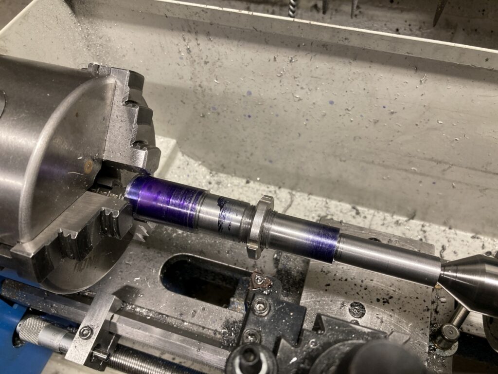
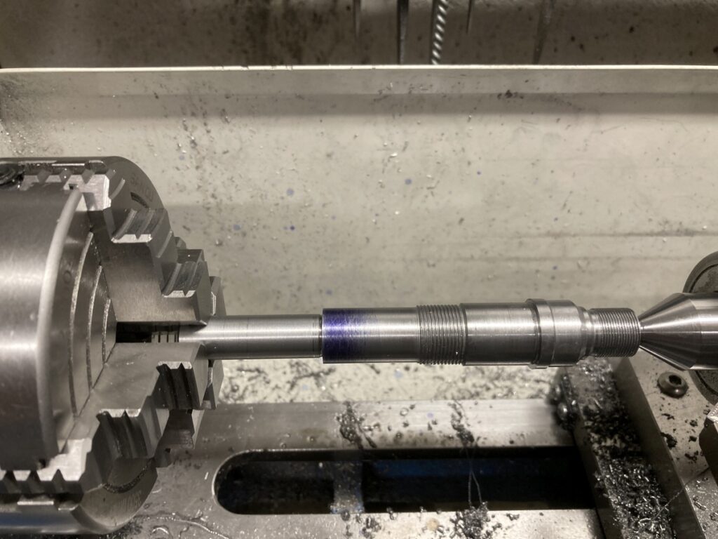
I made an ER11 spindle of a very similar design on my mini lathe. I was very pleased with the way that it came out – I couldn’t detect any runout in the spindle itself with an 0.002mm indicator, and about 4µm TIR on a tool in a decent quality collet. This was the sequence I used: With the stock held in a 3 jaw chuck, I machined the tail end as far as I could and cut the threads for the nose bearing clamp nuts (on my design), but only roughed the bearing journals.
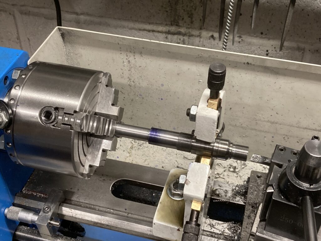
I then flipped the part around and held the tail end (centred) in the 4 jaw chuck. The other end was supported with a fixed steady while it was centre drilled so I could use a live centre for support while machining the outside of the collet chuck and cutting the collet nut threads.
I used the fixed steady again, without disturbing the part, to bore the collet recess and cut the internal taper for the collet. That was the bulk of the machining completed.
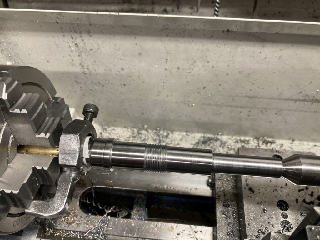
I then chucked a short piece of brass and cut it to match the collet taper (while the compound slide was set to the correct ER taper angle). I could then mount the spindle between centres, using the collet taper to support the ‘nose’ end of the spindle on the brass live centre with a dead centre in the tailstock. This setup was used to machine the bearing abutments and journals.
The journals were left 0.01mm oversize and then lapped to final size. I was very pleased that I managed to get them both pretty much spot on – just a few microns above nominal. There's a bit more description of the whole thing on the page I linked to in a previous post. I'm sure that there are other ways of doing it, but that's what worked for me. |
| Kiwi Bloke | 27/07/2023 02:29:27 |
| 912 forum posts 3 photos | Posted by Iain Downs on 26/07/2023 20:36:40:
The spindle mainly - it's quite complicated!
Iain Yes. More simplification required! Back in the '80s, when I was messing around with cars, I had a Ford Escort gearbox (2000) in pieces, next to an exploded diagram of a Triumph (Spitfire, IIRC) 'box. I was impressed how Ford had managed to simplify the whole thing, with far fewer components. It must have been easier, quicker and cheaper to manufacture, and far easier to strip and re-build than the Triumph, which was done the old-fashioned way. In addition, the Ford 'boxes were strong, reliable, and had a renowned, slick shift action. They were very popular (pretty well universal) among amateur motor racers, and constructors, such as the UK "Clubmans' Formula', which was getting close to Formula 3 lap times. I'm a long-time fan of simplicity! OK, what can be done, to satisfy Ian? Well, the machining of the housing, to get the bearing housings aligned, is not a trivial job. If you're going to machine a smaller ID at the tail end, you might as well machine an ID the same as at t'other end - it isn't more difficult. Then you can simplify bearing purchasing too... This allows the bulk of the shaft to be the same diameter, and the spacer to be plain-ended. Tail-end details will, of course, need to be adjusted also. I'm finding this journey towards simplicity interesting. Thanks for allowing (encouraging?) me to continue disrupting... |
| Kiwi Bloke | 27/07/2023 02:34:52 |
| 912 forum posts 3 photos | Addendum. Last suggestion means the tail bearing has to be fitted after the spindle has been fitted to the housing. This isn't a problem. The outer track should be a light push fit in the housing, and you have the screwed end of the shaft to take a nut and tube bearing pusher. It'll go together easily. The tail bearing bore in the housing must extend deeper along the bore, so the outer track of the bearing can float axially. |
| Andy_G | 27/07/2023 10:34:49 |
260 forum posts | Posted by Kiwi Bloke on 27/07/2023 02:29:27: ...the machining of the housing, to get the bearing housings aligned, is not a trivial job...
This is a powerful argument (in my mind, at least) for making the tail bearing OD smaller as it allows all of the bearing locations in the housing to be machined in the same operation, giving the best concentricity possible with given equipment. (They don't need to be *especially* accurate otherwise - the tail bearing bore is probably the most critical: to allow float without slop.) I'm not sure what material Steve is thinking of for the housing, but in the design with a spacer between the inner races only, I would suggest that the housing be made of steel, rather than aluminium, in order to avoid variations in bearing preload as the spindle warms up - I tried something similar with an aluminium housing and the temperature effect was remarkably noticeable. This will be the Rolls Royce of spindles when it's done! |
| Kiwi Bloke | 27/07/2023 11:33:58 |
| 912 forum posts 3 photos | Andy_G - Yes, I agree with everything you've said, except I'm less confident about the last para. It might turn out like a camel - designed by committee. Let's hope not: it should be good. it might, perhaps, become a sort-of ME standard spindle, in a similar way to Prof. Chaddock's Quorn spindle. Regarding machining the housing in one set-up: I suppose it depends on how confident one can be, working at the bottom of a deep hole. Boring and gauging the 'far end' of the housing, and how stiff the boring bar would be, given that it would neeed to be longer than the housing, have their own problems. Boring each end, supported on a good fixed steady, is the alternative, for both of our tail-end suggestions. Then, the three same-sized bearings job is easier. Even the single set-up idea would probably need a steady at the tailstock end. I would hope that temperature variations don't affect pre-load significantly, with an alloy housing, given the bearing pair spacing is so short, but agree steel is better. More reliable, running in a steady, too. Keep the ideas flowing - it staves off Alzheimer!
|
| Steve Crow | 27/07/2023 17:07:46 |
| 429 forum posts 268 photos | Here is version 8.
I've gone for a single nut at the rear. I know I could make the whole assembly in one piece but I lke the idea of a "pulley carrier" so I can swap for different sizes. Not immediately apparent but I've put flats on the nose just behind the nut for collet tightening. This increase the front overhang but only by 2.5mm. I want to go for different size bearing as I think I'll stand a better chance of getting the diameters optimal on two separate shorter journals rather than one long one. When it comes to the spacer, I'm going to retain the stepped ends. Again, I stand a better chance of getting a nice snug fit if I've only got the ends to worry about. It will only take a few minutes extra work to bore out so It's hardly complicating things. Same with the tail end of the spacer. I'l stick with the 8mm step as that is the SKF recommended abutment. Again, a few minutes extra work. I don't want to over simplify for the sake of it! I'll describe how I plan to machine the parts later. Steve |
| Steve Crow | 27/07/2023 19:06:50 |
| 429 forum posts 268 photos | How I plan to make the spindle- Cut a piece of 10mm EN8 to slightly over total length. Face and centre drill one end. Hold the last 10mm of the unfaced end in centred 4-jaw with live centre at the other end. Turn the plain shank at tail end of the spindle. I will make it a bit longer than the drawing as it has to be held in a collet later. Turn the 7mm pulley section to 6.98 then the bearing journal to 7.01. Continue along the spindle, one diameter at a time (leaving the journals 0.01 oversize), until the 9.5mm section is done. The idea is to leave as much meat and stiffness in the spindle as possible while turning. A fixed steady might help but I think I'll get away with it. When the turning is done, single point the thread and do any chamfering. Then lap journals to suit bearings. Remove from chuck, reverse and hold 9.5mm diameter in a collet. Then drill, bore, taper bore, thread etc. Basically complete the ER8 chuck. Before the next stage, you will have needed to make the spacers and rear lock nut assembly. Assemble spindle, bearings, spacers nuts etc. and nip everything up. Hold the tail end plain shank in a good collet or well centred 4-jaw. Support front bearings in a fixed steady and adjust so the 9.5mm diameter is as true as you can get. Move clock to the collet taper bore and check run-out. Its only going to be as good as your 9.5mm collet during the last process. If its good enough, your done! If not, take a light skim along the taper until it is. This last idea was adapted from the I'll describe the housing machining later. Steve |
| Steve Crow | 27/07/2023 19:29:45 |
| 429 forum posts 268 photos | I'm not sure that given the ER 8 collets and the small cutter/drill you are expecting to use whether you need two bearings at the front. I've just upgrade a sensitive vertical drill by using a bought spindle with ER11 collets. The spindle is a straight 12mm diameter X 150 mm long and in my case runs in oilite bushes. I don't know if similar spindle are available for ER8 but it would save a lot of work. Hi Clive, I do realise that this is probably grossly over-engineered for my purposes, but I wanted a design that could be replicated and scaled easily. Also I'm quite fond of a bit of over-engineering! My very first thought when on embarking on this was to use a bought ER8 spindle as you said. They are available in 8mm shank at just the right length (65mm) but I wasn't sure about turning down and thread cutting as the shanks are hardened. Not to mention the satisfacion of making it myself. My current project is upgrading a tiny sensitive drill. It runs in a 1/4" spindle which I'm remaking with an ER8 chuck. I would have used a bought spindle for this but they are not availble in imperial sizes. This did run in steel bushes which I've replaced with Oilite. Steve |
| duncan webster | 27/07/2023 22:28:37 |
| 5307 forum posts 83 photos | The 9.5 diameter is very short to grip on a collet, and the collet might not be dead true either. You could copy GHT's method, fit one of the nose end bearings, support it in a fixed steady and grip the pulley end in either a collet or a 4 jaw. The collet seat must then be coaxial with the spindle. |
| Clive Steer | 27/07/2023 22:49:46 |
| 227 forum posts 4 photos | Hi Steve. My "sensitive drill" was actually designed for tapping but I can find no info regarding the manufacturer. I'll post some pictures to see if anyone can identify it. I'm currently putting together the BLDC motor system to drive it. In my case I chose the ER11 spindle with 12mm x 150 mm shaft as it was an almost exact match for the original. I say almost because the original spindle was strangely 11.86mm diameter so hence the need to rebush. Most of the other parts on the "drill" appear to be metric so I believe it may be Swiss or German. As a tapping device it would not need to be run at high RPM so plain bushes would be fine. CS
|

Please login to post a reply.
Magazine Locator
Want the latest issue of Model Engineer or Model Engineers' Workshop? Use our magazine locator links to find your nearest stockist!
Sign up to our Newsletter
Sign up to our newsletter and get a free digital issue.
You can unsubscribe at anytime. View our privacy policy at www.mortons.co.uk/privacy
Latest Forum Posts
- hemingway ball turner
04/07/2025 14:40:26 - *Oct 2023: FORUM MIGRATION TIMELINE*
05/10/2023 07:57:11 - Making ER11 collet chuck
05/10/2023 07:56:24 - What did you do today? 2023
05/10/2023 07:25:01 - Orrery
05/10/2023 06:00:41 - Wera hand-tools
05/10/2023 05:47:07 - New member
05/10/2023 04:40:11 - Problems with external pot on at1 vfd
05/10/2023 00:06:32 - Drain plug
04/10/2023 23:36:17 - digi phase converter for 10 machines.....
04/10/2023 23:13:48 - More Latest Posts...
- View All Topics
Support Our Partners


Shopping Partners
Subscription Offer

Latest "For Sale" Ads
- Reeves** - Rebuilt Royal Scot by Martin Evans
by John Broughton
£300.00 - BRITANNIA 5" GAUGE James Perrier
by Jon Seabright 1
£2,500.00 - Drill Grinder - for restoration
by Nigel Graham 2
£0.00 - WARCO WM18 MILLING MACHINE
by Alex Chudley
£1,200.00 - MYFORD SUPER 7 LATHE
by Alex Chudley
£2,000.00 - More "For Sale" Ads...
Latest "Wanted" Ads
- D1-3 backplate
by Michael Horley
Price Not Specified - fixed steady for a Colchester bantam mark1 800
by George Jervis
Price Not Specified - lbsc pansy
by JACK SIDEBOTHAM
Price Not Specified - Pratt Burnerd multifit chuck key.
by Tim Riome
Price Not Specified - BANDSAW BLADE WELDER
by HUGH
Price Not Specified - More "Wanted" Ads...
Get In Touch!
Do you want to contact the Model Engineer and Model Engineers' Workshop team?
You can contact us by phone, mail or email about the magazines including becoming a contributor, submitting reader's letters or making queries about articles. You can also get in touch about this website, advertising or other general issues.
Click THIS LINK for full contact details.
For subscription issues please see THIS LINK.
Digital Back Issues


Donate

 Register
 Log-in
Model Engineer Magazine
- Percival Marshall
- M.E. History
- LittleLEC
- M.E. Clock

ME Workshop
- An Adcock
- & Shipley
- Horizontal
- Mill

Subscribe Now
- Great savings
- Delivered to your door

Pre-order your copy!
- Delivered to your doorstep!
- Free UK delivery!
All Forum Topics > General Questions > Multiple Bearings in Spindle