Forum sponsored by:

Wonky threads using die
| File Handle | 22/11/2021 14:54:14 |
| 250 forum posts | " for example using metric drills (available in straightforward 0.1mm increments) rather than Imperial Letter and Number drills, which are bonkers illogical. " I have often wondered how number and letter drill sizes came about. does anyone know or is it lost in history? A mixture of metric, imperial and letter / number drills does give you even more choice for fine tuning sizes. |
| SillyOldDuffer | 22/11/2021 16:26:08 |
| 10668 forum posts 2415 photos | Posted by Keith Wyles on 22/11/2021 14:54:14:
... I have often wondered how number and letter drill sizes came about. does anyone know or is it lost in history? ... Best answer I've heard is the sizes come from the way wire was originally handmade by pulling metal through dies. The apparatus consisted of a stout bench with a large lever at one end. At the other a long bar was bashed through a fixed die until the end could be gripped and the rest drawn through the die by heaving on the lever. The diameter, or gauge, of the die was limited by the maximum force the lever could apply to swage the metal down to size without breakages. Smaller diameters were made by pulling a large gauge wire through a smaller die, with the size of the hole adjusted again to avoid breaking anything. Thus wire gauges step down through a series of diameters that don't have an obvious numeric relationship - they depend on ductility, the strength of the metal being pulled, the strength of the die, and the power of a manually operated lever. The sizes were found by experiment, not calculated, and the resulting series of gauges became de-facto standards. When the Victorians upgraded to drawing wire with steam they could draw wires in any diameter. But because many customers were committed to the old gauge sizes, they carried on producing them. There were dozens of different gauge systems, and my 1948 Engineer's Handbook spends half a page introducing them: quite easy to order the wrong one. Gauge sizes have gradually been supplanted by rational diameters but there are still survivals. They say the gauge of modern railway track is derived from Roman Chariots axles for much the same reason: once a standard is embedded they take forever to change, even if the original reason has become daft! Dave
|
| Brian Morehen | 22/11/2021 18:03:02 |
 191 forum posts 11 photos | Die holders seem to have mostly metric sizes BA and small Whit & Bsf that i Have are 15/16 which from memory will only go to 1/4 Whit 5/16 Whit and similar go to a 1. 5/16 Die holder which i think stops at 1/2 whit. I also have some BA Dies that go from 10BA to 4BA that are 9/16 Dia . To get a perfect fit you may have to make small ring to fit your Die to then hold your Die , A poor fit may break your die? I maybe slightly wrong about these sizes as i am reliying on my memory Good luck and time you will win. |
| Steve355 | 23/11/2021 19:52:11 |
| 321 forum posts 235 photos | Posted by Howard Lewis on 20/11/2021 21:11:15:
You can make or buy. Making can be a useful learning exercise, and give confidence in using the lathe. (
What is the handle that sticks out if the back of the die holders for?
|
| Howard Lewis | 23/11/2021 21:06:11 |
| 7227 forum posts 21 photos | Ideally, the Tailstock Die Holder should be able to "float" on the arbor, so that the chamfer on the end of the work centres the Die, and the newly cut threads do not have the task of pulling the Tailstock along the lathe bed. (With fine threads that is very likely to strip the thread; certainly with ME 40 threads which are only 0.016" (0.406 mm ) deep ). I ensured that my Die Holder body, and the Tap Holder body were a loose fit on the arbor for just that reason. Howard |
| Steve355 | 23/11/2021 23:12:49 |
| 321 forum posts 235 photos | Posted by Howard Lewis on 23/11/2021 21:06:11:
Ideally, the Tailstock Die Holder should be able to "float" on the arbor, so that the chamfer on the end of the work centres the Die, and the newly cut threads do not have the task of pulling the Tailstock along the lathe bed. (With fine threads that is very likely to strip the thread; certainly with ME 40 threads which are only 0.016" (0.406 mm ) deep ). I ensured that my Die Holder body, and the Tap Holder body were a loose fit on the arbor for just that reason. Howard That is interesting. Do you have any pictures of it? Or is there something similar online? my 1.5” bar I bought to make it is coming tomorrow! thanks Steve |
| Steve355 | 24/11/2021 10:15:39 |
| 321 forum posts 235 photos | Ok, I just watched blondiehacks video on the subject and I think I know what to do now. |
| Mike Poole | 24/11/2021 10:59:23 |
 3676 forum posts 82 photos | The Arrand tailstock die holder allows the actual die holder to be adjusted to be axially true, this is achieved by the holes for the attachment screws being oversized to allow the holder to be perfectly aligned before tightening. Although Arrand has closed as far as I know there is still some available, I think Rotagrip listed them not long ago. Mike |
| Howard Lewis | 24/11/2021 16:21:12 |
| 7227 forum posts 21 photos | I am a coward where turning Morse Tapers is concerned, on the grounds that I may not get the angle right, and the turned surface finish will certainly be inferior to that of a commercially ground one. So the Stub Morse Taper arbor is mounted in the Headstock spindle and drilled / reamed /bored to suit the arbor that will be fitted. Often the arbor size is determined by the size of material available, quite likely to be Silver Steel. The arbor is then chamfered and faced to length, and pressed / Loctited into place. The bore in the body of the Holder is then deliberately made a few thou over size, relative to the arbor, so that it can float to self centre on the chamfer on the end of the job. The Holder is bored to take the largest OD Die, and holders made that have a spigot the same OD, and length as the largest Die, with a bore that accepts the smaller OD Dies. The holders are drilled and tapped with three holes for grubscrews, at 45 degree spacing around the circumference. Or you can cheat by making your main holder body and buying the smaller Die Holders I put a tapping into the OD of the main holder body, so that a stud can be screwed in, to rest against the edge of the Toolpost, to resist rotation whilst in use. I made a similar holder taking ER collets, to hold Taps . There is a chanfer on the end of the bore, to help the Tap to self centre on the bore. Sometimes the torque required is such that the Tap slips inn the collet. In such case the Tap is usually sufficiently engaged for the work to be transferred from chuck to vice, so that tapping can be completed by carefully using a Tap Wrench and muscle power Although this entails cutting a 1.5 mm pitch thread for the size of collets that you choose. (It seems that the thread dia is that of the next collet size up. 25 mm for ER 20, 32 mm for ER25, and so on. ) Howard |
| Steve355 | 25/11/2021 21:49:24 |
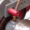
| 321 forum posts 235 photos | Well, I sorted it out for now… I got a ER25 collet that fitted the lathe, and used the tailstock to hold the die stock in position. After a few goes I got fed up with turning by hand and engaged the motor on the lowest speed. It worked pretty well, maybe not perfect, but pretty close and much better than trying to thread on my voice. I have some steel rod coming to make a die holder at the weekend.
It worked pretty well, maybe not perfect, but pretty close and much better than trying to thread on my voice. I have some steel rod coming to make a die holder at the weekend. see below, old bent one and new not bent one.
Thanks to everyone who gave me advice.
|
| AJAX | 26/11/2021 01:27:48 |
| 433 forum posts 42 photos | Posted by Steve355 on 23/11/2021 19:52:11:
Posted by Howard Lewis on 20/11/2021 21:11:15:
You can make or buy. Making can be a useful learning exercise, and give confidence in using the lathe. (
What is the handle that sticks out if the back of the die holders for?
It's easy to turn a Morse taper if you already have a male taper you can copy. Set a dial guage on the tool post and rotate the compound slide until it tracks the taper accurately. If you do it that way you don't need to worry about the taper angle dimension. |
| not done it yet | 26/11/2021 08:29:18 |
| 7517 forum posts 20 photos | Morse taper blank end arbors are available (Arceurotrade from just over a fiver?). These are accurately ground to size and sold for making items such as you are proposing. Morse tapers need to be precise (fitted using engineers blue) preferably with a hard ground surface. I don’t make Morse tapers ‘cos they are cheap and accurate - I always try to keep a couple in stock for making arbors as and when required (otherwise shipping adds to the cost). I have one commercial Morse taper (my last ever purchase from ‘ban good’ for anything that must not be a substandard item). It would have destroyed anything that was associated with it, if used. Ajax might well say it is easy. But it does require a bit of expertise when setting the taper angle, so not recommended (by me) for a beginner. |
| ega | 26/11/2021 11:16:28 |
| 2805 forum posts 219 photos | Setting the topslide to a precise angle can be frustrating - repeatedly this way and that (or "et patati et patate" as the French have it) - but the problem can be simply eased with a GHT-type screw adjuster:
|


Please login to post a reply.
Magazine Locator
Want the latest issue of Model Engineer or Model Engineers' Workshop? Use our magazine locator links to find your nearest stockist!
Sign up to our Newsletter
Sign up to our newsletter and get a free digital issue.
You can unsubscribe at anytime. View our privacy policy at www.mortons.co.uk/privacy
Latest Forum Posts
- *Oct 2023: FORUM MIGRATION TIMELINE*
05/10/2023 07:57:11 - Making ER11 collet chuck
05/10/2023 07:56:24 - What did you do today? 2023
05/10/2023 07:25:01 - Orrery
05/10/2023 06:00:41 - Wera hand-tools
05/10/2023 05:47:07 - New member
05/10/2023 04:40:11 - Problems with external pot on at1 vfd
05/10/2023 00:06:32 - Drain plug
04/10/2023 23:36:17 - digi phase converter for 10 machines.....
04/10/2023 23:13:48 - Winter Storage Of Locomotives
04/10/2023 21:02:11 - More Latest Posts...
- View All Topics
Support Our Partners


Shopping Partners
Subscription Offer

Latest "For Sale" Ads
- Reeves** - Rebuilt Royal Scot by Martin Evans
by John Broughton
£300.00 - BRITANNIA 5" GAUGE James Perrier
by Jon Seabright 1
£2,500.00 - Drill Grinder - for restoration
by Nigel Graham 2
£0.00 - WARCO WM18 MILLING MACHINE
by Alex Chudley
£1,200.00 - MYFORD SUPER 7 LATHE
by Alex Chudley
£2,000.00 - More "For Sale" Ads...
Latest "Wanted" Ads
- D1-3 backplate
by Michael Horley
Price Not Specified - fixed steady for a Colchester bantam mark1 800
by George Jervis
Price Not Specified - lbsc pansy
by JACK SIDEBOTHAM
Price Not Specified - Pratt Burnerd multifit chuck key.
by Tim Riome
Price Not Specified - BANDSAW BLADE WELDER
by HUGH
Price Not Specified - More "Wanted" Ads...
Get In Touch!
Do you want to contact the Model Engineer and Model Engineers' Workshop team?
You can contact us by phone, mail or email about the magazines including becoming a contributor, submitting reader's letters or making queries about articles. You can also get in touch about this website, advertising or other general issues.
Click THIS LINK for full contact details.
For subscription issues please see THIS LINK.
Digital Back Issues


Donate

 Register
 Log-in
Model Engineer Magazine
- Percival Marshall
- M.E. History
- LittleLEC
- M.E. Clock

ME Workshop
- An Adcock
- & Shipley
- Horizontal
- Mill

Subscribe Now
- Great savings
- Delivered to your door

Pre-order your copy!
- Delivered to your doorstep!
- Free UK delivery!
All Forum Topics > Beginners questions > Wonky threads using die