Forum sponsored by:

Gear hobber (mechanical)
| Michael Gilligan | 26/02/2016 14:16:28 |
 23121 forum posts 1360 photos | Welcome, Duncan !! MichaelG. |
| Gustav Thiesen | 26/02/2016 17:02:05 |
| 16 forum posts 18 photos | Many thanks Duncan! My special aim is not to make a 127 teeth gear. This is only one of the possibilities. My main target is to build up a hobbing machine, which should be able to cut prime number gears to. One reason for this is, that I have made a dividing head last year. Because it should also manage prime numbers, i made a compound dividing head. But when it was finished i saw that the handling was prone to errors. So I have transformed the construction to a differential dividing head. I had to cut 12 gears for this. I made them by poor mans hobbing method. To facilitate and to get better results I want to make this machine. |
| Bazyle | 26/02/2016 17:39:50 |
 6956 forum posts 229 photos | John, the hobber does have an auto feed option if you look at the gears behind the worm driving the blank. Duncan, Great to see a practical ME use of printing. Of course a printer is a lot of trouble and expense to make so perhaps on a par with a hobber. But lots of whirling gears - got to be a winner. Had a look at the gear trains for making 127 and one option is 125 & 126, but for 126 you need a 63 prime. So you can make a 63 using 60 and 57 - oh dear another prime and so it goes on. |
| Bazyle | 27/02/2016 13:03:47 |
6956 forum posts 229 photos | Looking around the professional gear hobbers it appears they often don't have a differential. Instead they may knock up a quick prime as required on a dividing head then use it to give the exact ratio. They are of course into mass production so worth the effort. It is much easier with computers now but in the past you could get tables with eg 14000 ratios from gear sets listed. |
| John Haine | 27/02/2016 13:21:55 |
| 5563 forum posts 322 photos | Umm... 9x7=63?
Posted by Bazyle on 26/02/2016 17:39:50: John, the hobber does have an auto feed option if you look at the gears behind the worm driving the blank. Duncan, Great to see a practical ME use of printing. Of course a printer is a lot of trouble and expense to make so perhaps on a par with a hobber. But lots of whirling gears - got to be a winner. Had a look at the gear trains for making 127 and one option is 125 & 126, but for 126 you need a 63 prime. So you can make a 63 using 60 and 57 - oh dear another prime and so it goes on.
|
| Bazyle | 27/02/2016 14:19:10 |
6956 forum posts 229 photos |
|
| Ajohnw | 27/02/2016 15:45:30 |
| 3631 forum posts 160 photos |
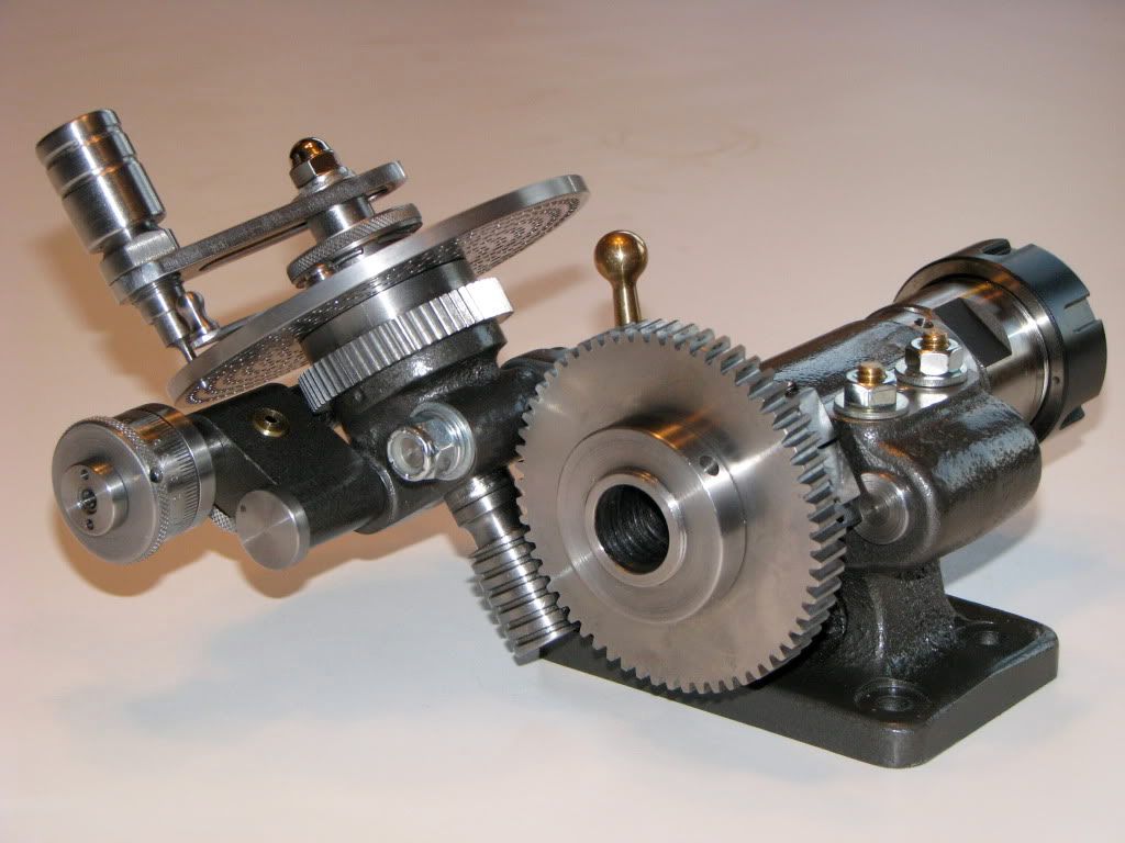
More for others that might be reading the thread. This is G Thomas's solution
As is often the case with these sort of designs all can be made on a Myford but the worms and wheels are usually bought. His BIG thick book goes through making it pretty thoroughly. Some people would buy the plates too. It's interesting to note that who ever made this one may have stuck to a long plain hole through the spindle of a size that also accepts the collet chuck. The short bar at the side is for a centre. One could be made based around a suitable small tailstock or fabricated. My one by Dore or Westbury has a 2 morse socket and a myford spindle nose on it. Fine but if I want to use the hole I need something with 2 morse on it - a pain to make. A plain diameter mandrel is easy. John - Edited By Ajohnw on 27/02/2016 15:48:44 |
| Ajohnw | 27/02/2016 16:05:56 |
| 3631 forum posts 160 photos | 63 teeth isn't a problem with the plates Brown and Sharp came up with which gives these with 60T worm wheel. They were intended for 40T. I would have thought any design of plate would need the same base primes.
I mentioned B&S because I noticed some Vertex stuff with parts I could use that also had plates but I wondered why they had departed from the usual hole counts so gave them a miss. I think the Cincinati design had yet more holes. Dore or Westbury went for fewer holes and no 63. John - |
| John Haine | 27/02/2016 16:43:15 |
| 5563 forum posts 322 photos | Since the question of the accuracy of digital dividing came up earlier in this thread I thought that I would see if I could measure how well my Ward / Myford divider does.
The only way I have to measure angles conveniently is a Wixey gauge, so first I bolted an angle plate to my VH6 rotary table, set vertical on the mill table, and rotated the VH6 by various amounts, initially in 1 degree, then 10, then 45 degree increments. During this the mill drive was running as a little bit of vibration seems to make the Wixey behave better - I think it may have a very small amount of stiction. The Wixey indication was never more than 0.1 degree out, and happily came back to zero after a complete rotation. Then I set up the digital DH on the table, with a 4J holding a steel plate horizontal to take the Wixey, and repeated the measurements - with exactly the same results. Setting the DH up for 127 divisions, the angle readings agreed exactly with theory for each division at least to the resolution of the angle gauge (which is only 0.1 degree of course). My controller is set up for 4x microstepping, or 48000 steps per rev with the 60:1 worm drive in the Myford DH. Minimum theoretical angular resolution is 0.0075 degrees (with all the caveats about microstepping). I don't think I'm going to worry about the accuracy of digital dividing for what I do. |
| Michael Gilligan | 27/02/2016 17:30:38 |
23121 forum posts 1360 photos | Posted by John Haine on 27/02/2016 16:43:15:
Since the question of the accuracy of digital dividing came up earlier in this thread I thought that I would see if I could measure how well my Ward / Myford divider does. . Thank You, John ... That's a very useful contribution to the communal knowledge. If you have the will to do it, I can suggest another test which might give a more definitive 'proof'. Make two 'identical' plates [any awkward count (maybe 7) would do] with nicely drilled holes ... Then check whether a set of dowel pins will fit them:
... Just a suggestion; not a request MichaelG. |
| Ajohnw | 27/02/2016 18:05:27 |
| 3631 forum posts 160 photos | I was only pointing out that steppers usually have a 5% step error that also varies with load John. There are some electronic solutions about. This one seems to have been going for a long time and not changed since 2012. There may be others Sounds like he had problems with keyboards. One approach Eddistone used on their radio's was to pole and shift into a byte - All 1's is one state and all 0's another, inbetween undefined. I've used a similar technique using state counters. Many moons ago I used edge trigger interrupts with no state times - oh dear but the first job I ever did like that. There is was another one looking at using a lower step count motor for higher holding torque. Also another that accepted G code for cnc. I haven't noticed any software for either of these. John -
|
| John Haine | 27/02/2016 20:23:47 |
| 5563 forum posts 322 photos | Michael, maybe when I have the DH set up in a config where I can drill I may give that a go. I can recommend the Steve Ward controller. He sells a complete kit, it's easy to build and works well. I could use a lower step count, say 24000, which would mean the motor is only 2x microstepping, so holding torque would be better perhaps, but there is a trade off between inherent resolution and precision here I think, not sure where the optimum is. |
| John Stevenson | 27/02/2016 20:32:36 |
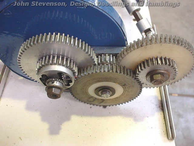
 5068 forum posts 3 photos | Diff fitted to a CES hobber.
|
| Ajohnw | 27/02/2016 23:30:15 |
| 3631 forum posts 160 photos | Posted by Bazyle on 26/02/2016 17:39:50:
John, the hobber does have an auto feed option if you look at the gears behind the worm driving the blank. Duncan, Great to see a practical ME use of printing. Of course a printer is a lot of trouble and expense to make so perhaps on a par with a hobber. But lots of whirling gears - got to be a winner. Had a look at the gear trains for making 127 and one option is 125 & 126, but for 126 you need a 63 prime. So you can make a 63 using 60 and 57 - oh dear another prime and so it goes on. The example given on the web isn't a sensible way of doing it Bazyle. If you look at the chart I posted earlier 127T is 13 holes on a 39 plate with a 56 and 44 gear plus 2 idlers. That is very probably with a 40T worm wheel. There's the rub really. If some one lacks a table and has 3 plates with 100's of holes in them, rather a lot of possible holes between each division and on top of that a selection of gears working out what to use is likely to be a bit tough as there are a LOT of possible combinations. Not an easy thing to handle as numbers like 127 are irrational. Probably the best option is to find a table some one else has produced. I think there is one in machinery's, also probably based on a 40T worm wheel. Checking that head does use a 40:1 worm wheel and comes with plates with 15,16,17,18,19,20,21,23,27,29,31,33,37,39,41,43,47 and 49 holes. The gears look like typical change wheel values.24,24,28,32,40,44,48,56,64,72,86 and 100 teeth. They give divisions of all numbers up to 500 starting at 51. From a quick look all numbers up to 50 are covered by the plates used the normal way. Must admit when I first came across model engineering items like these I was a bit bemused by the extra teeth on the worm wheels. John - |
| John Haine | 28/02/2016 07:42:28 |
| 5563 forum posts 322 photos | It's my inner pedant, I can't resist it, but 127 is a prime integer, not irrational. |
| Michael Gilligan | 28/02/2016 08:18:47 |
23121 forum posts 1360 photos | For info. This incudes a good introduction to differential indexing: MichaelG. |
| Ajohnw | 28/02/2016 10:30:24 |
| 3631 forum posts 160 photos | True John but my brain was locked in 1/127 which is. 1 over this and that is what makes dividing systems work. Actually I read the table incorrectly. It should be gears with 56 and 24 teeth. Didn't enlarge my pdf view enough. To be honest as 1/127 is irrational my gut feeling would be that correcting 1/120 with another simple fraction wont be exact. Having caught a cold and it being early Sunday morning not much chance of getting my head round the math to find out. John - |
| Bazyle | 28/02/2016 11:33:17 |
6956 forum posts 229 photos | AJW. You keep diverting into Differential indexing but this thread is about a Hobber with a differential. The maths is very different. It is also not about the best way to make a one off gear but about how to make any gear with a hobber. Professional hobbers come with not one but two sets of gears from 20 to 100 that's 160 gears not the dozen for a dividing head. For the benefit of the very few reading around the subject of hobbing be aware that authors often use the term 'feed' both for the movement of the blank across the hob during the cut and for the movement of the hob along its axis which is available on a professional machine. |
| Ajohnw | 28/02/2016 12:19:54 |
| 3631 forum posts 160 photos | You mentioned the differential dividing head Bazyle followed by a criticism that may or may not be correct. I just responded. As I understand it the hob feed is for feeding the cut in tangentially with a tapered hob rather than plunge cutting. What I suspect the OP needs is details of the math behind a differential hobber or the design that some one has produced and lacking the math a table. There are some forums about on the web where maths type questions are sometimes answered. Might be a solution for the OP as they appear to like tougher ones. Good link Michael. There is another type with 2 dividing plates but I believe that is mostly used for pure angular divisions. John - |
| Gustav Thiesen | 28/02/2016 12:27:46 |
| 16 forum posts 18 photos | To John Stevenson: I'm looking for this differential addon of the CES hobber. Can you give more information about the construction and the use of this addon or otherwise do you know whether the plans of collegeengineering will give this information? |


 Then there was that optical one on ebay for a song.
Please login to post a reply.
Magazine Locator
Want the latest issue of Model Engineer or Model Engineers' Workshop? Use our magazine locator links to find your nearest stockist!
Sign up to our Newsletter
Sign up to our newsletter and get a free digital issue.
You can unsubscribe at anytime. View our privacy policy at www.mortons.co.uk/privacy
Latest Forum Posts
- *Oct 2023: FORUM MIGRATION TIMELINE*
05/10/2023 07:57:11 - Making ER11 collet chuck
05/10/2023 07:56:24 - What did you do today? 2023
05/10/2023 07:25:01 - Orrery
05/10/2023 06:00:41 - Wera hand-tools
05/10/2023 05:47:07 - New member
05/10/2023 04:40:11 - Problems with external pot on at1 vfd
05/10/2023 00:06:32 - Drain plug
04/10/2023 23:36:17 - digi phase converter for 10 machines.....
04/10/2023 23:13:48 - Winter Storage Of Locomotives
04/10/2023 21:02:11 - More Latest Posts...
- View All Topics
Support Our Partners


Shopping Partners
Subscription Offer

Latest "For Sale" Ads
- Reeves** - Rebuilt Royal Scot by Martin Evans
by John Broughton
£300.00 - BRITANNIA 5" GAUGE James Perrier
by Jon Seabright 1
£2,500.00 - Drill Grinder - for restoration
by Nigel Graham 2
£0.00 - WARCO WM18 MILLING MACHINE
by Alex Chudley
£1,200.00 - MYFORD SUPER 7 LATHE
by Alex Chudley
£2,000.00 - More "For Sale" Ads...
Latest "Wanted" Ads
- D1-3 backplate
by Michael Horley
Price Not Specified - fixed steady for a Colchester bantam mark1 800
by George Jervis
Price Not Specified - lbsc pansy
by JACK SIDEBOTHAM
Price Not Specified - Pratt Burnerd multifit chuck key.
by Tim Riome
Price Not Specified - BANDSAW BLADE WELDER
by HUGH
Price Not Specified - More "Wanted" Ads...
Get In Touch!
Do you want to contact the Model Engineer and Model Engineers' Workshop team?
You can contact us by phone, mail or email about the magazines including becoming a contributor, submitting reader's letters or making queries about articles. You can also get in touch about this website, advertising or other general issues.
Click THIS LINK for full contact details.
For subscription issues please see THIS LINK.
Digital Back Issues


Donate

 Register
 Log-in
Model Engineer Magazine
- Percival Marshall
- M.E. History
- LittleLEC
- M.E. Clock

ME Workshop
- An Adcock
- & Shipley
- Horizontal
- Mill

Subscribe Now
- Great savings
- Delivered to your door

Pre-order your copy!
- Delivered to your doorstep!
- Free UK delivery!
All Forum Topics > General Questions > Gear hobber (mechanical)