Forum sponsored by:

Allchin slide valve help please
Slide valve width?
| John Baguley | 11/08/2013 19:06:52 |
 517 forum posts 57 photos | Hi Nigel,
Glad you've hopefully got it sorted. I'll second Neil's comment on your workmanship Neil, Even when Stephenson's gear is correctly designed, there will always be movement of the die block in mid gear. It's inherent in the design. With the eccentrics correctly set, the movement of the die block should be twice the lap + lead. Think of the eccentrics as doing the same job as the combination lever in Walschaert's gear. Stephenson's is a little complicated in that the lead varies over the range of the reverser travel whereas with Walschaert's the lead is constant . Normally with Stephenson's, the lead increases as you move from full gear to mid gear. To avoid too much lead towards mid gear, the valve gear is often designed to give perhaps zero or even negative lead in full gear. The design of Stephenson's on traction engines is actually quite poor anyway. The suspension of the expansion link at the top is always going to give poor valve events compared to suspending it in the centre as done on most locos. Perhaps the designers of traction engines weren't too fussed about getting equal cut offs etc. ! John |
| JasonB | 11/08/2013 19:53:07 |
 25215 forum posts 3105 photos 1 articles | Its a 4 shaft engine so rods should be crossed, |
| John Baguley | 11/08/2013 21:10:33 |
517 forum posts 57 photos | Not sure, I think it's an open rod valve gear as the rods are open when the eccentrics are towards the link. Crossed is when the rods are crossed when the eccentrics are towards the link. As Jason says though, four shaft TEs usually had crossed rods so I could be wrong. John Edit - Looking at Nigels photos, it is a crossed rod layout so the lead will decrease as you go from full gear to mid gear which ties in with what Nigel found. Hmmm, wonder how you put crossed rods into a simulator - they seem to be set up for open but there must be a way. Edited By John Baguley on 11/08/2013 21:12:55 Edited By John Baguley on 11/08/2013 21:15:34 Edited By John Baguley on 11/08/2013 21:21:28 |
| Robert Dodds | 11/08/2013 21:48:59 |
| 324 forum posts 63 photos | Hi all,
I'm not at all into TEs but am intrigued with mechanical motions. I've just been looking at a simulation of Stevenson (not crossed) that shows the eccentric pins at 80 degrees either side of the crankpin. Am I mis-reading Nigel's pictures because to me the eccentric pins look as though they are at 100 degees or more eitherside of the crankpin. Bob D
|
| GoCreate | 11/08/2013 22:55:07 |
 387 forum posts 119 photos | Hi everyone Thanks for all the interesting replies. I am not sure what you mean by normal or crossed eccentric links but I hazard a guess that these are normal and crossed would have the eccentric arms connection to the reversing link swapped over. For your reference I have attached some info from the Allchin book which I hope answers your questions.
For now I have to leave it a few days. I feel confident it's OK and will run it on air a a couple of weeks. Thanks
Nigel |
| JasonB | 12/08/2013 07:49:22 |
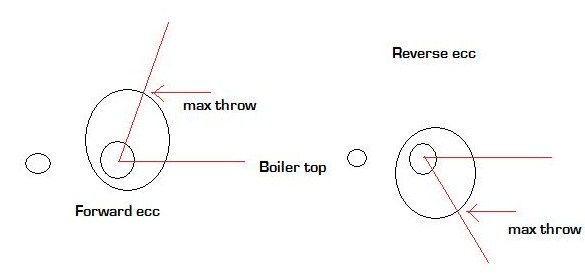
25215 forum posts 3105 photos 1 articles | As I said at the beginning the eccentric should lead the crank by 90deg plus 7-8deg , Hughes says 7.5. So the angle between crank and eccentric is 90+7.5 = 97.5 The angle of the template is 82.5deg being the complementary angle of 97.5 This is the drawing I have given several people on how to get the initial timing of a TE, which is basically the same. based on a 4 shaft engine where the flywheel turns clockwise in forward gear. The template is held against the horizontal boiler top.
Edited By JasonB on 12/08/2013 07:50:18 |
| GoCreate | 12/08/2013 09:30:19 |
387 forum posts 119 photos | Hi Jason Thanks again for your info. Something must be wrong on my engine, set at the 82.5 deg (97.5 deg the other way round) Hugh says that the slide valve should reciprocate with the reversing link in mid gear such that as the crank is rotated the inlet ports should just become visible via a thin black line appearing. However, on my engine, in mid gear the reciprocation of the slide valve was only 1mm, significantly less than indicated by Hugh's book. Also in full gear the inlet ports did not open until the crank turned through about 40 deg. So then I must have made some error somewhere, hopefully something I can identify and fix easily. Thanks again Nigel |


Please login to post a reply.
Magazine Locator
Want the latest issue of Model Engineer or Model Engineers' Workshop? Use our magazine locator links to find your nearest stockist!
Sign up to our Newsletter
Sign up to our newsletter and get a free digital issue.
You can unsubscribe at anytime. View our privacy policy at www.mortons.co.uk/privacy
Latest Forum Posts
- hemingway ball turner
04/07/2025 14:40:26 - *Oct 2023: FORUM MIGRATION TIMELINE*
05/10/2023 07:57:11 - Making ER11 collet chuck
05/10/2023 07:56:24 - What did you do today? 2023
05/10/2023 07:25:01 - Orrery
05/10/2023 06:00:41 - Wera hand-tools
05/10/2023 05:47:07 - New member
05/10/2023 04:40:11 - Problems with external pot on at1 vfd
05/10/2023 00:06:32 - Drain plug
04/10/2023 23:36:17 - digi phase converter for 10 machines.....
04/10/2023 23:13:48 - More Latest Posts...
- View All Topics
Support Our Partners


Shopping Partners
Subscription Offer

Latest "For Sale" Ads
- Reeves** - Rebuilt Royal Scot by Martin Evans
by John Broughton
£300.00 - BRITANNIA 5" GAUGE James Perrier
by Jon Seabright 1
£2,500.00 - Drill Grinder - for restoration
by Nigel Graham 2
£0.00 - WARCO WM18 MILLING MACHINE
by Alex Chudley
£1,200.00 - MYFORD SUPER 7 LATHE
by Alex Chudley
£2,000.00 - More "For Sale" Ads...
Latest "Wanted" Ads
- D1-3 backplate
by Michael Horley
Price Not Specified - fixed steady for a Colchester bantam mark1 800
by George Jervis
Price Not Specified - lbsc pansy
by JACK SIDEBOTHAM
Price Not Specified - Pratt Burnerd multifit chuck key.
by Tim Riome
Price Not Specified - BANDSAW BLADE WELDER
by HUGH
Price Not Specified - More "Wanted" Ads...
Get In Touch!
Do you want to contact the Model Engineer and Model Engineers' Workshop team?
You can contact us by phone, mail or email about the magazines including becoming a contributor, submitting reader's letters or making queries about articles. You can also get in touch about this website, advertising or other general issues.
Click THIS LINK for full contact details.
For subscription issues please see THIS LINK.
Digital Back Issues


Donate

 Register
 Log-in
Model Engineer Magazine
- Percival Marshall
- M.E. History
- LittleLEC
- M.E. Clock

ME Workshop
- An Adcock
- & Shipley
- Horizontal
- Mill

Subscribe Now
- Great savings
- Delivered to your door

Pre-order your copy!
- Delivered to your doorstep!
- Free UK delivery!
All Forum Topics > Traction engines > Allchin slide valve help please