Forum sponsored by:

Jason's Firefly .46 Build
| JasonB | 15/07/2012 13:54:01 |
 25215 forum posts 3105 photos 1 articles | Piston A lump of 25mm CI bar was put in the lathe, faced off and turned 0.010" overdia and about twice the length needed.
The end was then drilled then followed by boring to finished depth and diameter
The turned length was then sawn off and transfered to the rotary table, centred and the end located.
The wrist pin hole was then done making sure not to break through and allowing for the dia being larger than finish size.
The table was rotated 180deg and the 1.0mm hole put in.
Without removing the work from the chuck the table was mounted horizontally and clocked true to the mill axis, this ensured that the conrod slot is exactly at right angles to the wrist pin hole. I drilled two holes on 5mm ctrs 3/16" then plunged with 5/16" and 7/16" slot drills to remove most of the waste.
It was then just a simple matter of milling to the 12mm finished size
With the milling complete the embrio piston can be parted off a little over length
A simple mandrel was made to hold the piston, the OD is a little less than piston finish size and the short spigot a good fit into the underside of the piston. The piston is place on the end, the pin slipped into the hole and then as the piston is turned the screw pulls it tight to the mandrel.
The piston can then be faced back to length
Then turned and honed until it just starts to enter the liner
I used the same mandrel to lap the piston to the liner but just turned the liner back and forth by hand Not under power. A tiny amount of 1000g is placed onto the piston and the liner slowly fitted to it adding plenty of oil, no more grit until a good fit is achieved.
And here we have the finished liner & piston
Edited By JasonB on 15/07/2012 13:57:55 |
| Terryd | 15/07/2012 16:00:42 |
 1946 forum posts 179 photos | Just a question on the piston, Does it really have to be cast iron, could it not be made from Ali running in steel as in a full size i.c. engine. Sorry if that is a dumb question but I've not had any experience of model i.c. engines before and intend to build this as soon as my last project is completed. Thanks for your great build diary Jason, it is proving to be helpful and am sure that it will be a boon when I get down to building. Best regards Terry Edited By Terryd on 15/07/2012 16:01:31 |
| Jeff Dayman | 15/07/2012 16:47:21 |
| 2356 forum posts 47 photos | TerryD This is a ringless engine. In full size engines with aluminum pistons, rings are used on the pistons, and the pistons have a few thou clearance to the bores. An aluminum piston in a steel liner without rings will have problems sealing and with galling unless the exact expansion is calculated, knowing the exact operating temp. Also the bore will need microfinishing to exact size. This type of sub .0001" work was done on many Japanese commercial model airplane engines but not for full size IC engines as far as I know. For the Firefly the CI piston in a steel bore, lapped to fit, is an excellent choice for a simple to make model IC engine that will run well for a long time if some oil is introduced with the fuel. JD |
| JasonB | 15/07/2012 17:05:54 |
25215 forum posts 3105 photos 1 articles |
Not much I can add to that I have used ali pistons on several IC engines but as Jeff says thae have all had rings mostly CI but one with vitron o rings Any reason you don't want to use CI Terry, its nice stuff to work with.
J |
| JasonB | 15/07/2012 17:40:53 |
25215 forum posts 3105 photos 1 articles | Gudgeon Pin Not much to say or show on this except to say make sure its a good fit in the piston, lap if needed. Little End Plug Start with a bit of bronze, turn the spigot to a good fit in the gudgeon pin hole
Turn the OD to be a fraction less than the pin and drill the 1.0mm hole. I find a bit of cutting fluid helps when drilling bronze as it stops the drill bit getting hot and sticking. Then part off.
Hold lightly by the spigot and round over the end and thats it done.
Carb Barrel Spacer This is quite straight forward work, turn OD and then the smaller dia, face to length and drill the hole, ease all corners before parting off just over length.
Grip by the smaller dia and face back the flange to 1.2mm thick, ease corners.
|
| JasonB | 15/07/2012 17:52:16 |
25215 forum posts 3105 photos 1 articles | Fuel Nipple I decided to use 1/4"x40ME thread on this rather than M6 so started by turning down a length to 1/4" dia.
Cut the thread using the tailstock die holder.
Use a small parting tool to cut the relief at the end of the thread, reduce the end to 2.35mm dia and then drill the hole, I went about half way from each end.
Part off and then screw the threaded end into a suitable hole in some scrap. I actually have several lengths of brass hex with threaded holes in one end and a male thread on the other all in various ME sizes they really come in handy whan making steam and fuel fittings. I used a parting tool to cut the reduced dia behind the hose barb.
Turn down the remails to 4.25 and then cut the hose barb, I could not be bothered to set the topslide to 6deg so just swung the tool so the back edge was at an angle and used that.
Finish drilling the hole and round the end and the corners off the hex with a file and thats another bit out of the way.
|
| Ramon Wilson | 15/07/2012 18:20:15 |
 1655 forum posts 617 photos | That's coming along nicely now Jason - mind if I make a comment on the lapping ? For those doing this for the first time - on this kind of I/C engine - it's best if when lapping the cylinder the lap is predominently, though not exclusively, inserted from the lower end of the liner. The reason for this is that doing it from one end will induce a slight taper, which, if done from the lower end is of a distinct advantage from the performance point of view but not so if the other way round. Re the piston material - Jeff, Terry, As far as I'm aware I don't think there are or were many commercial model engines that had an ally piston running directly in a plain unhardened or uncoated steel liner. As you say an ally piston would be fitted with a ring(s), usually a single, though sometimes two, conventional ring or a dykes type. ABC engines on the other hand have an Ali piston running in a Brass liner which has been Chromed. The ali used here is normally of high silicon content too. The engines I've made so far have used cast iron pistons. When the Nova was made, EN1a was used for the liner to aid machining those fine fins. This has bedded in well and has very good compression. On the Racers, after enquiring on here I used cast iron on one liner and alloy steel on the other. The cast iron though still good quickly lost it's initial seal compared to the other. Just after these were made I found an article extolling the virtues of running cast iron pistons in En1a liners up to a limit of around a 1" bore. The Eta's were made using this material and so have the latest G32's. The Eta's particularly exhibiting very good compressive seals. There is a link on this months MEN to a page from Duke Fox of Fox engines that makes very interesting reading and confirms that this is indeed an ideal combination. The only thing I would add is to make the cast iron piston as light as possible - it's surprising just how thin the sections can be. Doing so will go a long way to reducing vibration.
Keep up the fine posting Jason, I look forward to seeing it's first run
Regards - Ramon |
| JasonB | 15/07/2012 18:50:40 |
25215 forum posts 3105 photos 1 articles |
Thanks Ramon, I did infact do most of the lapping from the bottom up, still have the marks in my hand from that narrow lip with the small notch
The piston also entered the bottom of the liner but not the top before lapping so must have got the taper about right. J Edited By JasonB on 15/07/2012 18:51:18 |
| Bruce Voelkerding | 15/07/2012 19:17:18 |
| 77 forum posts 7 photos | Jason, I tap holes in my shop like you show - with the tap wrench in the MIDDLE of the tap. However, I find it a nuisance adjusting the drill chuck, so over the years I have turned up "bushings". The OD is just a clean-up cut for concentricity then I drill to fit the tap shank diameter (actually I relieve the tap hole till the guiding surface is one diameter long - don't know if this is required). At first I thougth I would be making one for each tap, but some do work for multiple taps. Bruce |
| Ramon Wilson | 15/07/2012 19:31:13 |
1655 forum posts 617 photos |
Sounds good Jason, not long to go now then eh? BTW how did you get on with the laps ease of expansion - the screw looks much more able than mine was - how thin/thick was the inner annular wall of the lap? Ramon |
| JasonB | 15/07/2012 19:56:42 |
25215 forum posts 3105 photos 1 articles | Bruce, sounds like a good idea particularly for the regularly used taps. Ramon, the lap was no problem to expand, I set the topslide to approx 2deg to cut the taper, over the 30mm length of the lap this gave me a wall thickness of 3mm at the thin end to 4mm at the thick end. OD is 21mm average bore about 14mm and I cut 10 slots about 1/2 way through. I threaded the end 7/16x40 for nice fine adjustment and put a couple of flats on the nut to take a 3/8" spanner. J
|
| Terryd | 15/07/2012 21:24:57 |
1946 forum posts 179 photos |
Posted by JasonB on 15/07/2012 17:05:54:
Not much I can add to that I have used ali pistons on several IC engines but as Jeff says thae have all had rings mostly CI but one with vitron o rings Any reason you don't want to use CI Terry, its nice stuff to work with.
J Hi Jason, No, I don't have any reason not to use ci but I am interested in the theory and am eager to learn and investigate alternatives, even at my advanced years. Best regards Terry |
| Martin W | 16/07/2012 10:20:24 |
| 940 forum posts 30 photos | Hi This is slightly 'Off Topic' but regarding Bruce's comment on the way that Jason mounts the Tap Wrench on the body of the tap. Warco have recently brought this ++TOOL++ out which looks as if it will do the same or similar job without the need to grip the tap halfway up the shank, normal disclaimer re vested interests.
Great post Jason and very nice work to boot, want to pics of it running too Cheers Martin |
| JasonB | 21/07/2012 20:38:44 |
25215 forum posts 3105 photos 1 articles | Crankshaft Another bit of the 30mm EN8 was chucked up with about 40mm sticking out, faced, center drilled with a BS 0 bit and then roughed out to about 8mm.
Then a bit more was exposed and the step for the drive nut roughed out a little over dia.
I then held it by what will be the web, supported with the tail stock centre and reduced the bearing area down to 13mm.
You may have noticed that I am using a holder that makes use of teh other two corners of blunt CCMT inserts, I find this very good for roughing cuts, it whizzed through the EN8 with 0.050" depth of cut producing a nice pile of swarf.
I then reversed the part in the chuck, faced off, drilled out to 8.5mm reduced the OD to finished size and chamfered all corners.
Now I had a face to work from the web was turned to thickness plus the 0.2mm for the raised area around the pin, bearing dia turrned ready for honing and the larger 0.2mm raised area formed.
The other diameters were finish turned to dia and length before the usual chamfering.
The 12mm dia was then honed until it just started to enter the bearing.
The 1/4"x28 UNC thread was cut on the end with the use of the tailstock die holder.
Then over to the mill to add some shape to the web using a boring head.
And repeated for the other side, now the cutting fluid has been wiped off you can see I also used the DRO to spot the crank pin position.
Holding the crank in a vee block I lightly marked a vertical line on the end while it was tilted to 40deg.
This line was then used to make sure the crank was held at the correct angle for milling.
Here the flat area and the 8mm slot have been milled.
Then the flat for the drive nut
Cont'd
Edited By JasonB on 21/07/2012 21:01:11 |
| JasonB | 21/07/2012 21:00:54 |
25215 forum posts 3105 photos 1 articles | To hold the crankshaft I reused an old block of ali that had been used for various jigs, it wa sbored to take the shaft and grub screws used in two existing holes to hold the crank, to prevent them damaging the surface a slug of soft ali wire was dropped into the hole first.
It was then just a case of clocking in the pin position and drilling to 5.5mm *see below I also added the 0.2mm raised area around the hole.
Crank pin I deviated from the drawing and used 7/32" silver steel which was a good push fit in the 5.5mm hole, not much machining to show but face to length and chamfer the ends.
So here we have the crankshaft and pin.
Which were pressed together in the mill vice
So they looked like this
I then turned up a taper mandrel from a bit of 3/8 alloy rod and used this to hold the crankshaft while it was hand lapped with 1000g until a nice fit in the bearing.
And here is the finished item with the drive nut on the end.
And all assembled with thrust washer and driver, no noticable end play but turns freely with a nut against the driver and a whiskers clearance on the backplate.
J Edited By JasonB on 21/07/2012 21:04:51 |
| JasonB | 22/07/2012 13:43:04 |
25215 forum posts 3105 photos 1 articles | Conrod I found it was only a few pence more to buy 1"x1" HE15 than 12x13mm so ordered 4" from M-machine which gave me plenty in reserve should I have a scrapper, bandsaw soon gave me a usable bit.
This was cleaned up in the mill with a flycutter
Once de-burred it was centred up in the milling vice
The two holes were drilled and then reamed
A simple holder was made from 3/8" brass and the conrod screwed to this so the little end could be rounded to 8mm dia
A quick alteration to the brass holder and the big end was rounded to 9mm taking the cut into the two sides to give 8mm between cuts
0.5mm was taken off each side using the rounded end of the flycutter to blend the curves
The waist was cut using a hand ground radius corner cutter Note the drawing states 10mm dia typical but is actually drawn with a 5mm dia or 2.5mm radius, take your choice, I went for the smaller.
The width of the big end was then machined back as required.
The oil holes were added with a BS0 centre drill
And thats the conrod finished
Could not resist putting a few bits together, even with the head off and just holding the backplate on by hand I can feel the vacuum in the crankcase as the piston rises before the port opens, so must be doing something right.
J |
| JasonB | 23/07/2012 19:56:10 |
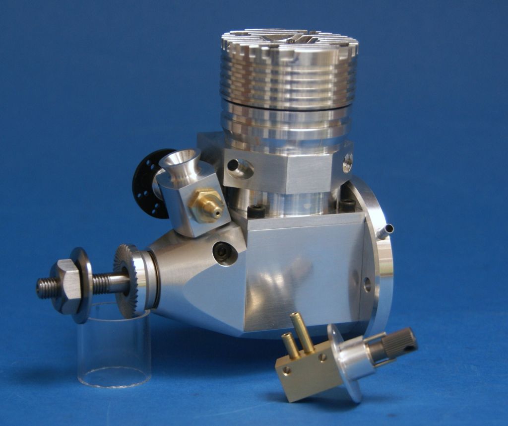
25215 forum posts 3105 photos 1 articles | Carburettor Body Once again I have deviated slightly on this one partly as I did not have any 3/4" hex bar and partly because I wanted a less bar stock look. Starting with a length of 1" dia bar the spigot and step were turned using the inlet in the crankcase to test fit the spigot to.
The hole was than drilled and all corners chamfered
Sufficient was sawn off the bar and then holding by the spigot I roughed out for the inlet trumpet.
Then used a mini boring bar to cut the internal taper
Without altering the top slide angle a round nosed tool was used to cut the external profile
Transfering the work to the rotary table the two sides were milled flat and to finished width
I then drilled tapping size before using an FC-3 cutter for the 10mm counterbore, this gives a flat bottomed hole with the advantage of a turn or two more thread than the drilled hole shown, its also a better finish for a good fit of the barrel.
Tap the hole and while in this orientation drill and tap the 2.5mm screw hole
Rather than using a hex shape I cut the front and back to a shallow convex profile using a boring head, this does need a slight clearance cut to miss the cylinder barrel
Finished job, well actually I took the pic before drilling and tapping the two retaining screw holes.
J |
| Jeff Dayman | 23/07/2012 21:00:18 |
| 2356 forum posts 47 photos | Hi Jason, The crankshaft and carburetor look excellent, beautiful work as usual. One 'design' question - what seals the carb spigot to the crankcase? I am sure you have a close fit between carb spigot and crankcase, but ideally this should be sealed gas-tight. An o-ring or flat silicone gasket could be used if space and / or suitable counterbore were planned for at the joint. If there is no room, a smear of RTV could be used as a last resort. Just some thoughts.... (I had problems years ago in commerciallly-made RC aircraft engines with bad sealing in this area and rear crankcase cover seals leaking causing some running issues. I fixed several of these leaks with RTV sealant but felt it was a bit of a rough fix at the time.) Again, great job so far! JD Edited By Jeff Dayman on 23/07/2012 21:00:48 |
| JasonB | 23/07/2012 22:27:34 |
25215 forum posts 3105 photos 1 articles | Funny enough I was in two minds to leave off the step on carb spigot and fit an O ring but thought I Would try it first as Alex says it is a Gasget less design. If needbe I'll ad a smear of liquid gadget anywhere that needs it or machine the step off and go with the O ring. J |
| JasonB | 27/07/2012 20:35:17 |
25215 forum posts 3105 photos 1 articles | Carb Barrel
As the cross hole is quite close to the edge I chose to drill first a few mm from the end and also from larger stock (1/2"
It was then turned and faced to size before lapping to the carb body
To finish its then just a case of drilling, tapping parting and facing to length
Mixing Disc This is fairly straightforward tutning to form the spigot, drill and then part off a bit over long
Before reversing in the chuck and facing to thickness
Transfer to the mill and add the holes, I put the linkage one in line with the pins but it makes little difference.
Mixer Body A suitable lump of brass was fished out of the scrap box and machined to 11.5x8.0mm
The centre of the hole was marked and set to run true in teh 4-jaw and the spigot turned a nice running fit in the disc
It was then drilled, tapped and counterbored. Make sure you use a M4x0.5 metric fine thread if going with the OS needle
Needle was test fitted before removing from chuck.
Then over to the mill to drill the fuel passages and counterbore for the pipe stubs
Flip it on its side and drill the fixing holes
Job Done
Add the tubes and thats the mixer assembly done
And the final parts, a thick washer and nut to retain the prop
Thats the making complete, hope to get it running this weekend, stay tooned.
J |


Please login to post a reply.
Magazine Locator
Want the latest issue of Model Engineer or Model Engineers' Workshop? Use our magazine locator links to find your nearest stockist!
Sign up to our Newsletter
Sign up to our newsletter and get a free digital issue.
You can unsubscribe at anytime. View our privacy policy at www.mortons.co.uk/privacy
Latest Forum Posts
- *Oct 2023: FORUM MIGRATION TIMELINE*
05/10/2023 07:57:11 - Making ER11 collet chuck
05/10/2023 07:56:24 - What did you do today? 2023
05/10/2023 07:25:01 - Orrery
05/10/2023 06:00:41 - Wera hand-tools
05/10/2023 05:47:07 - New member
05/10/2023 04:40:11 - Problems with external pot on at1 vfd
05/10/2023 00:06:32 - Drain plug
04/10/2023 23:36:17 - digi phase converter for 10 machines.....
04/10/2023 23:13:48 - Winter Storage Of Locomotives
04/10/2023 21:02:11 - More Latest Posts...
- View All Topics
Support Our Partners


Shopping Partners
Subscription Offer

Latest "For Sale" Ads
- Reeves** - Rebuilt Royal Scot by Martin Evans
by John Broughton
£300.00 - BRITANNIA 5" GAUGE James Perrier
by Jon Seabright 1
£2,500.00 - Drill Grinder - for restoration
by Nigel Graham 2
£0.00 - WARCO WM18 MILLING MACHINE
by Alex Chudley
£1,200.00 - MYFORD SUPER 7 LATHE
by Alex Chudley
£2,000.00 - More "For Sale" Ads...
Latest "Wanted" Ads
- D1-3 backplate
by Michael Horley
Price Not Specified - fixed steady for a Colchester bantam mark1 800
by George Jervis
Price Not Specified - lbsc pansy
by JACK SIDEBOTHAM
Price Not Specified - Pratt Burnerd multifit chuck key.
by Tim Riome
Price Not Specified - BANDSAW BLADE WELDER
by HUGH
Price Not Specified - More "Wanted" Ads...
Get In Touch!
Do you want to contact the Model Engineer and Model Engineers' Workshop team?
You can contact us by phone, mail or email about the magazines including becoming a contributor, submitting reader's letters or making queries about articles. You can also get in touch about this website, advertising or other general issues.
Click THIS LINK for full contact details.
For subscription issues please see THIS LINK.
Digital Back Issues


Donate

 Register
 Log-in
Model Engineer Magazine
- Percival Marshall
- M.E. History
- LittleLEC
- M.E. Clock

ME Workshop
- An Adcock
- & Shipley
- Horizontal
- Mill

Subscribe Now
- Great savings
- Delivered to your door

Pre-order your copy!
- Delivered to your doorstep!
- Free UK delivery!
All Forum Topics > Work In Progress and completed items > Jason's Firefly .46 Build