Forum sponsored by:

A Challenge - How Would You Machine This Part?
| John Stevenson | 03/06/2011 23:28:15 |
 5068 forum posts 3 photos | Come on then Andrew, don't keep us in suspenders ? John S. |
| Andrew Johnston | 04/06/2011 09:21:27 |
 7061 forum posts 719 photos | Oeeeer, we can't have that; fortunately my imagination isn't that vivid! The short answer is that the gears were machining on a 4-axis CNC mill. It is not possible to machine them on a manual mill, with one extremely tedious exception. I have a number of comments and queries, which I'll post later today after I've been flying, or decided that the weather isn't playing ball. Regards, Andrew |
| Andrew Johnston | 04/06/2011 11:18:54 |
7061 forum posts 719 photos | So, the weather is not good, we've got alto-stratus and some alto-cu here, otherwise known as crap off the North Sea, so flying has been postponed. Thanks to everyone for the replies. Rather than one long post I'll do several shorter posts. First a few general notes. The mating crown wheel will be 36 teeth, so John S wasn't far out. These are true bevel gears, so they cannot be cut on a horizontal mill with a dividing head. I'll discuss this in another post, as there are some things I would like to clarify on the cutting of bevel gears on a manual mill. Congratulations to WALLACE for getting the answer correct in the first reply, CNC all the way. JasonB is also correct, these are for the differential on a 4" scale SCC Burrell. I admit that casting was the one solution I hadn't thought of. I know that full size engines often used 'as cast' gears in the differential, presumably mainly for cost reasons. Since the full size engines often used only 6 or 8 teeth on the bevel pinions they would have also been heavily undercut and hence difficult to produce by machining. It would have been an interesting exercise to make the patterns and have the gears cast, but of course you still have the problem of how to make the pattern, chicken and egg? I'd use the CNC mill to make the pattern; it's a couple of keystrokes in the CAD program to alter the scaling of the solid model to allow for shrinkage, about 1/8" per foot or 1% for cast iron. Donald, yes you could use a rat tailed file. But the radius at the bottom of the small end is just over 2mm, so may I suggest that a mouse tail file would be more appropriate. You'd probably have to ask for a wee, sleekit, cow'rin, tim'rous beastie file though. On books, I do have Ivan Laws book, it's good as far as it goes, but, it seems rather weak on the theory. I haven't heard of the Marshall book, I'll have to have a look. I normally use 'Gear Design Simplified' from Industrial Press, Machinery's Handbook and the internet for design information. Regards, Andrew Edited By Andrew Johnston on 04/06/2011 11:19:44 |
| Andrew Johnston | 04/06/2011 12:26:31 |
7061 forum posts 719 photos | Now to discuss how, and why, I did this machining the way I did. The whole farrago started because I didn't agree with some of the numbers given on the drawings for the bevel gears in the differential for the traction engines I am building. I'm not interesting in spending hours making parts only to find they don't fit because the drawings are wrong. I like to make sure I understand the numbers and how the part fits with its related parts before machining. Having spent some time working through the design of bevel gears I concluded that the drawings are slightly wrong; 3 thou out, not much, but 3 thou is 3 thou! It is not possible to machine a true bevel gear on a horizontal mill; it needs some adjusting afterwards and needs a special cutter. So naturally I turned to the parallel depth method. I did in fact redesign the whole differential using parallel depth bevel gears. I did, of course, consider buying ready made gears from my supplier, but I wasn't terribly happy about the quality, the gears were expensive, and being awkward I wanted to machine them myself. Eventually the little light bulb illuminated (dull of course as it's an energy saving bulb) and it occurred to me I could CNC mill the gears. Obviously to do this I needed a solid model. Easy enough to do in principle; I knocked up a basic gear in about 30 minutes. But as always the devil is in the detail. We all know that the tooth form is an involute curve, but how do you draw an involute curve in the CAD system. What part of the involute curve do you use, which of the infinite number of involute curves is correct, what about undercut clearances and root radii? It took me many hours of book buying, reading, drawing and internet searching to sort all this out. Plus the inevitable wobblies with the CAD software. In contrast the CAM program and G-code generation was fairly quick, apart from an annoying bug in the CAM software. For some specific operations the G-code generated didn't agree with the toolpath shown. Here's the sequence of machining, first the blank, it's just a cylinder, diameter and length are easy to get from the CAD/CAM system. Next, after the roughing cuts: 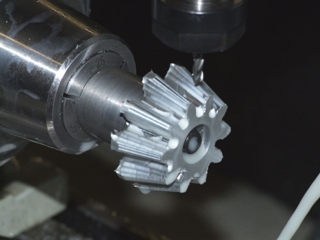 And after the final cut: 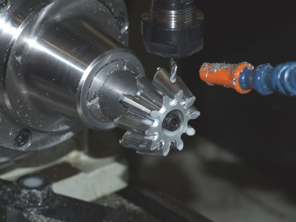 All cutting was done with a 4mm three flute carbide ball nose cutter running at 5000rpm and 400mm/min, giving a conservative chip load of 0.027mm per flute. Total cutting time was about 2 hours 45 minutes. The chamfers on the back and front were done on a normal lathe, using the same arbor mounted in a collet chuck. How long have I spent doing this? Too long! I didn't keep a note of times, but the following are rough estimates: Design calculation on the proper bevel gears: 8 hours Designing the differential using parallel tooth bevels: 4 hours Designing a 3D model of the bevel gear with correct tooth forms: 40+ hours CAM software and G-code generation: 8 hours Machining a backplate and fitting a 5C collet chuck to the mill: 6 hours Loading, setting and cutting time for two pinions: 6 hours It's interesting to note that by far and away the biggest task was the design phase. Of course I now know a lot more about bevel gears (!) so if I do it again I'll be a lot quicker. As an aside the cutting time for the bevel gears wasn't wasted. During the time to machine the two gears, over two nights, I cleaned up the workshop, made and ate supper twice, and did most of the turning trials that have been reported elsewhere on this forum. Regards, Andrew |
| JasonB | 04/06/2011 13:19:16 |
 25215 forum posts 3105 photos 1 articles | So will you be doing a detailed write up for MEW
 Is it teh LSM one as I thought they did the castings? or are they just the blanks.
Jason
Edited By JasonB on 04/06/2011 13:24:23 |
| Andrew Johnston | 04/06/2011 14:48:22 |
7061 forum posts 719 photos | Hi Jason, Yes, I will be writing this up for submission to MEW. And before there's any whinging about yet more CNC, the majority of the article will be about the design of bevel gears, as well as a summary of the machining methods, manual and CNC. The actual CNC machining part will be quite short, as it's not that interesting. I'm building my SCC Burrells from the Filby drawings, as modified by LSM; but I bought my drawings, and all the castings, from John Rex in Pontefract. I've had a quick look on the LSM website and they don't mention castings for the differential pinions, just the crown wheels. Similarly John Rex sells the crown wheel castings, but not the pinions. The John Rex crown wheels are just blank castings, I assume the LSM ones are similar. Regards, Andrew |
| Steve Withnell | 04/06/2011 15:30:57 |
 858 forum posts 215 photos | Hi Andrew,
Questions questions...
Which solid modeller are you using?
Is 10 teeth pushing it a bit? I thought 12 was considered the lower limit?
The design book I was given is "Gear Design Simplified" by Franklin Jones and its the best laid out /easiest to follow I've seen so far.
I've only cut parallel depth bevel gears so far, but they do work and don't whinge much...
Regards
Steve
|
| Andrew Johnston | 04/06/2011 16:01:06 |
7061 forum posts 719 photos | Hi Steve, There's nowt wrong with questions! I'm using Alibre for solid modelling. I have the 'Expert' version, so including sheet metal and all the bells and whistles. I've been using it for about 6 years now. I bought it primarily for my work, but it is also very useful for model engineering. For anything other than a simple arbor, or similar, I tend to design in Alibre to ensure that parts fit together, will move together without interfering and then be able to produce 2D drawings. It has a few foibles but overall I think it is good value for money. Solidworks was outside my budget. In the distance past I've used ProEngineer, but didn't get on with it, very difficult to use. That's the book! First time I used it, mumble, mumble, years ago I borrowed it from the library at RAE Farnborough, but eventually had to buy my own copy from Amazon. As I understand it 12 teeth for involute gears is about the limit without introducing undercut, which weakens the teeth, I think. Certainly the standard B&S style involute cutters only go down to 12 teeth. But there's no theoretical limit, just practical ones. Well may be a one tooth gear would be a bit difficult! Regards, Andrew Edited By Andrew Johnston on 04/06/2011 16:01:32 Edited By Andrew Johnston on 04/06/2011 16:02:27 |
| JasonB | 04/06/2011 17:13:38 |
25215 forum posts 3105 photos 1 articles | Andrew, there is a bit about machining the diff for a Burrell (singel cyl) but quite a bit is the same and they are John Rex parts on Conrads site though he went for parallel depth. |
| Steve Withnell | 04/06/2011 17:28:08 |
858 forum posts 215 photos |  This is the set of bevel gears I made for my Stuart Victoria. I'd like to claim I made these with a set of false teeth, so I don't need CNC, but it wouldn't be true. These are 40DP parallel depth, so not as manly as Andrews pucker 6DP gears, but they did the job. I set is 1:1 and the other set is 2:1. I ignored the advice regarding odd numbers of teeth because the engine was never likely to run more than an hour or two any way.
|
| Andrew Johnston | 05/06/2011 10:45:21 |
7061 forum posts 719 photos | JasonB: Thanks for the link to Conrad's site; an interesting read. At least I didn't fall into the trap of not having the number of teeth on the crown wheel divisible by 3 when I re-designed the differential using parallel tooth bevels. Steve: Wow, nice looking gears! I may be asking you for advice in the future; there are two bevel gears needed for the governor on my traction engines. I think they're about 20DP so milling by the CNC route will need a small cutter. So I may use the parallel depth method for them. Just one comment; the space between the teeth on the two gears to the left seems quite deep in relation to the tooth width. Is this a consequence of the parallel depth method? Regards, Andrew |
| Andrew Johnston | 05/06/2011 11:28:25 |
7061 forum posts 719 photos | Now for a brief discussion on the various methods of producing bevel gears. First, thanks to Nick for the drawings, very good! I'm sure the method would work, as would the use of a hacksaw and file. But my word it would be a bit tedious. I wonder what sort of templates would be needed to ensure accuracy, and how would you make them? As an aside Richard mentioned the Hiraoka books; I've heard good reports about them. I have a friend who has an obsession with Shay locomotives; I'll have to ask hin if he has the books. Now onto the suggestion by ady of using a shaper. I considered this too, essentially I guess one is making a crude Gleason bevel gear planer. It seems a lot of work though, and secondly my shaper is sadly out of action at the moment, awaiting repair of a broken casting. So finally we come to the production of the bevel gears on a milling machine. First, a statement; it is not possible to machine a true bevel gear on a conventional milling machine, with one caveat. JohnS has succinctly described the two approximation methods, so I won't repeat them here, but just make some comments. On the first method (that requires 'adjustment' afterwards) as I understand it the gear is designed using the DP at the outer diameter of the gear. An involute cutter is then selected that has the correct tooth form for this DP and the appropriate number of teeth. But, here's the difficulty, this cutter has to pass through the tooth gap at the small end of the gear. So you cannot use a standard involute cutter. Instead you need a special involute cutter that has the correct form but is thinner than standard. Can anyone confirm this? As far as I'm aware these cutters are no longer available; at least I couldn't find any, not even from China or India. I have made bevel gears in the past using this method, but I had the facilities of the main workshop at RAE Farnborough behind me. They lent me the special cutter required. Here are the gears prototyped in aluminium, the final gears were made in EN32 and were case hardened: 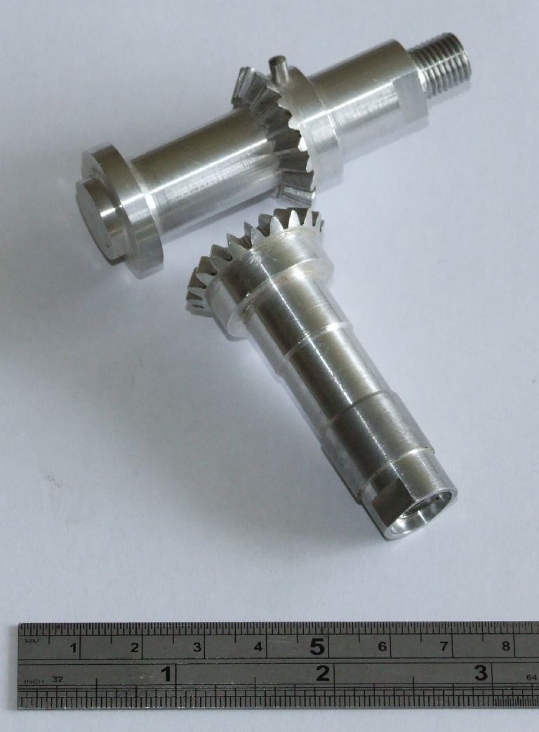 If you look closely at the lower gear you might be able to spot the 'deliberate' mistake. The parallel depth method avoids the need for a special cutter as the design is based around the DP at the smaller end, and hence a standard involute cutter is fine. Now onto the post by JohnS, really interesting. I downloaded the Gearotic demo last night and had a play. It looks very good, but I cannot output data from the demo so cannot see what the G-code looks like. Are the bevels generated true bevel gears, or do they use the parallel depth method? The other thing I couldn't see how to control was the stepover of the tool, which determines the surface finish, trading this off against run time. The cutting time JohnS got is much quicker than mine. I wonder if this is due to a coarser stepover, or a more sophisticated toolpath. My CAM system will only interpolate X and Z, The Y axis never moves and A is only used as an indexer. It would be more efficient to interpolate 3 or even 4 axes. This would also allow one to generate a 'Sturz' style cutting strategy which would be more efficient and give a better finish for a coarser stepover. Further I don't see why a tilting dividing head is needed? I didn't use one, but just used the 4th axis as an indexer, no cuts took place while the rotary table was moving. It would have been possible to cut the pinion using a 3 axis mill, but this would have required a long series end mill. A 4mm ball end cutter with a flute length of at least 22mm would be a bit delicate! I will be cutting the crown bevel gears using 3 axes, as the teeth are much flatter, so we don't need the 4th axis. Now, back to the caveat. It would be possible to machine a true bevel gear on a manual mill by essentially replicating what the CNC mill does. In other words a long list of X, Y, Z and A co-ordinates that are stepped through by twiddling the handles. It wouldn't half be tedious though. Regards, Andrew Edited By Andrew Johnston on 05/06/2011 11:32:20 |
| John Stevenson | 05/06/2011 12:34:25 |
5068 forum posts 3 photos | Andrew, Replies to questions from the Gearotic questions. Bevels are true bevels and not parallel depth bevels. Not sure what you see in the demo program but when you go to the output manager where you enter tool size, feeds etc you have a choice on depth of cut per pass, step over and how many 'slices' per pass you want to do, default is 10 but can be altered to suit. I tend to use 8 to get a decent finish but reasonable cutting times. Gearotic interpolates in 3 axis X, Y and A as it roll the gear, it basically mimics the Gleason but uses a rotation cutter in stead of a planing action. Gearotic uses a tilting dividing head as it doesn't move Z when cutting, head is tilted at root angle which is parallel to the bed. This is done to make the maths easier otherwise it would be interpolating in 4 axis. Now, back to your caveat. Somewhere I have a program based on a spread sheet, not done by me but by a guy who's name I can't think of at the moment to give recognition.  In it he uses the No 1 cutter which is from 135 teeth to a rack and takes a pass then moves over in Y, rotates the dividing head and takes another pass etc on both sides. Basically what Gearotic does but all manual moves. To be perfectly correct you would need a straight sided rack cutter and not the 135 tooth cutter which has some involute on it but I'm assuming this was the best idea using readily available off the shaft cutters. One number 1 cutter will do all gears in a range. Perhaps the program could be automated for doing your small bevel gears ? John S. |
| Nicholas Farr | 05/06/2011 17:23:52 |
 3988 forum posts 1799 photos | Hi Andrew, I,m pleased you liked my drawings, they were done while polishing off a large glass of Cótes Du Rhóne, and moving onto a Sauvignon Blanc. They were (if you hadn't guessed) a little tongue-in-cheek in their own way, (I thought the use of a mini grinder would have said it all).
I had gathered that they were done by CNC, but as I've had no experience with CNC or cutting bevel gears for that matter, and the fact that others had already suggested CNC, I thought I'd submit a some what comical alternative. Yes I agree with you, it would be a pretty tedious method, especially to get accuracy, and any templates would take as much, if not more work. They look a fine pair of gears BTW, and hope your cast iron ones turn out just as good. Regards Nick. Edited By Nicholas Farr on 05/06/2011 17:25:13 |
| mgj | 05/06/2011 19:04:40 |
| 1017 forum posts 14 photos | Well its good thing they had CNC when they made traction engines!! Andrew - you really have to ask why? Or I do, because it seems to be a very wonderful solution to a problem which never existed in the first place. Unless one simply wants to do it this way for fun - which is as good a reason as any, if one has the time and the pennies.. One simply doesn't need a true bevel for this application - and with the clearances in a TE diff, it wouldn't matter if you used lantern pinions. A parallel depth bevel is, accepted, an approximation, though it does offer certain advantages in running in certain circumstances. Despite the (very small) approximation, at 20 RPM you ain't going to notice, nor even when winching, and certainly not at the 1/2RPM differential velocity when the bevels are doing their differential bit. - And we go to all this trouble for something that can be chopped out of a standard bit of cast iron or steel? The calculations take about 5 minutes on a scientific calculator, order the cutter - it will be smaller than nominal but as you say, a standard off hte shelf DP cutter - , three evenings, a vertical mill, a simple dividing head and for addition, a DTI to set the blank roll. It will take longer to make the arbors to hold these blanks than it will do do the gear cutting, and you have saved the trouble and cost of getting everything cast anyway. And why do we need 4 axis CNC for something that was originally made in a blacksmiths shop? Forgive me, but it seems to me, this is a wonderful way of making a very simple bit of machining very complicated and expensive, for nil gain in performance. Did you hear BTW of the bid BAe put in in the 1980s for some NBC fan housings (sort of aircon units) to go in armoured vehicles. Most people used pressed steel housings. The BAe bid was 4 times the price of anyone elses- but then they intended to start with a huge chunk of steel and a milling machine? Edited By mgj on 05/06/2011 19:05:32 Edited By mgj on 05/06/2011 19:07:59 |
| JasonB | 05/06/2011 19:39:33 |
25215 forum posts 3105 photos 1 articles | As mgj says the full size were just as cast. If you have a copy of Gilberts Suppliment there are a couple of very good pics of the diff wheels on a Fowler and Marshal and you can easily see the sand cast texture.
I think they were run in with a mix if sand & grease
You don't need teh accuracy, it snot like a car diff going a 110s of rpm and finely adjustable preload. You can't adjust the preload on a TE and when the axle or 2nd shaft warms up and gets longer all those fine fits will all go to pot anyway.
You could always machine them from test wax which would be quick and use that as a pattern for lost wax casting, the finish would be more than usable, these are the as cast teeth on my fowler
Jason
Edited By JasonB on 05/06/2011 19:56:47 |
| Andrew Johnston | 05/06/2011 20:45:12 |
7061 forum posts 719 photos | Hi Nick, Yes, I rather gathered that the drawings were intended to be tongue-in-cheek, but nonetheless amusing.  They certainly lightened my day; excellent choice of accompanying beverages by the way! They certainly lightened my day; excellent choice of accompanying beverages by the way!I shall be interested to see how I get on cutting the cast iron. I'm nowhere near the speeds recommended by the cutter manufacturer for aluminium, in fact I'm running at the bottom end of the speeds they recommend for cast iron. So as a first pass I'll stick with the same speeds and feeds and see how I get on. Regards, Andrew |
| Andrew Johnston | 05/06/2011 21:14:19 |
7061 forum posts 719 photos | Hi JohnS, Thanks for the explanations of Gearotic. Now that I look at it with fresh eyes I see that the cutting information is available on the output page. I also now understand why the 5 axis is needed. Tormach do a 5 axis add-on, driven rotary table with a manual tilt, but it is pretty expensive and would be expensive to ship, plus VAT, plus import duty plus....well I expect you get the picture. I could machine a fixed block to tilt my rotary table, but I think I'll stick with my existing method for the moment. However, I am interested in Gearotic. I did look at it more than a year ago but decided against buying it. But now, after consulting the keeper of the purse strings, I think I will make a purchase. If nothing else I will be interested to look at the generated G-code and plot out the consequent toolpath. At some point I will need to machine a helical gear for the steering on the traction engines and Gearotic will give me another option, ie, CNC versus manual machining. Even if I decide to machine the helical gears manually Gearotic may help to generate a 3D model. Thanks again. Regards, Andrew |
| Colin Jacobs 1 | 05/06/2011 21:31:10 |
| 69 forum posts 2 photos | Posted by Donald Mitchell on 02/06/2011 16:52:53: I'd use my grandpa's old hacksaw and finish the teeth off with a nice rat tailed file I bought in Woolworths about 30 years ago; I can work to about 2/10 of a thou with that file, who needs CNC Donald In Bonnie Scotland And much more rewarding I bet |
| John Stevenson | 05/06/2011 22:27:47 |
5068 forum posts 3 photos | Andrew, Sorry have I misled you ? 5 axis isn't needed just a tilting dividing head in place of the 4th axis which will still be A. Then the normal X, Y, and Z axis. John S. |
Please login to post a reply.
Magazine Locator
Want the latest issue of Model Engineer or Model Engineers' Workshop? Use our magazine locator links to find your nearest stockist!
Sign up to our Newsletter
Sign up to our newsletter and get a free digital issue.
You can unsubscribe at anytime. View our privacy policy at www.mortons.co.uk/privacy
Latest Forum Posts
- *Oct 2023: FORUM MIGRATION TIMELINE*
05/10/2023 07:57:11 - Making ER11 collet chuck
05/10/2023 07:56:24 - What did you do today? 2023
05/10/2023 07:25:01 - Orrery
05/10/2023 06:00:41 - Wera hand-tools
05/10/2023 05:47:07 - New member
05/10/2023 04:40:11 - Problems with external pot on at1 vfd
05/10/2023 00:06:32 - Drain plug
04/10/2023 23:36:17 - digi phase converter for 10 machines.....
04/10/2023 23:13:48 - Winter Storage Of Locomotives
04/10/2023 21:02:11 - More Latest Posts...
- View All Topics
Support Our Partners


Shopping Partners
Subscription Offer

Latest "For Sale" Ads
- Reeves** - Rebuilt Royal Scot by Martin Evans
by John Broughton
£300.00 - BRITANNIA 5" GAUGE James Perrier
by Jon Seabright 1
£2,500.00 - Drill Grinder - for restoration
by Nigel Graham 2
£0.00 - WARCO WM18 MILLING MACHINE
by Alex Chudley
£1,200.00 - MYFORD SUPER 7 LATHE
by Alex Chudley
£2,000.00 - More "For Sale" Ads...
Latest "Wanted" Ads
- D1-3 backplate
by Michael Horley
Price Not Specified - fixed steady for a Colchester bantam mark1 800
by George Jervis
Price Not Specified - lbsc pansy
by JACK SIDEBOTHAM
Price Not Specified - Pratt Burnerd multifit chuck key.
by Tim Riome
Price Not Specified - BANDSAW BLADE WELDER
by HUGH
Price Not Specified - More "Wanted" Ads...
Get In Touch!
Do you want to contact the Model Engineer and Model Engineers' Workshop team?
You can contact us by phone, mail or email about the magazines including becoming a contributor, submitting reader's letters or making queries about articles. You can also get in touch about this website, advertising or other general issues.
Click THIS LINK for full contact details.
For subscription issues please see THIS LINK.
Digital Back Issues


Donate

 Register
 Log-in
Model Engineer Magazine
- Percival Marshall
- M.E. History
- LittleLEC
- M.E. Clock

ME Workshop
- An Adcock
- & Shipley
- Horizontal
- Mill

Subscribe Now
- Great savings
- Delivered to your door

Pre-order your copy!
- Delivered to your doorstep!
- Free UK delivery!
All Forum Topics > Workshop Techniques > A Challenge - How Would You Machine This Part?