Forum sponsored by:

My skeleton clock
The skeleton clock has come alive!
| NJH | 18/05/2011 10:17:41 |
 2314 forum posts 139 photos | Hi Sam I have sent you a PM Regards Norman |
| blowlamp | 18/05/2011 10:22:48 |
 1885 forum posts 111 photos | Sam.
That's some lovely work you've done there!
As for the Balance Spring, did you ever try wrapping the wire around a threaded mandrel to keep the pitch even?
Martin. |
| Sam Stones | 19/05/2011 01:28:55 |
 922 forum posts 332 photos |
Thank you Martin, I appreciate your comments. To answer your question - No, I haven’t tried a threaded mandrel, although I’m tempted to drive over to a friends toolroom and see if he will let me use one of his lathes. Although wrapping the wire around a threaded mandrel was suggested by several members in another ME thread (Balance Springs II - under the topic - Clocks), I have to say that while I loved screw-cutting, for this purpose the Hobbymat doesn’t impress me one bit. I miss my Myford too much!!! In his ME series c.1972, John Stevens, the clock designer describes in a fair amount of detail, how he made the (flat-section) spring. It involves more than just winding however, because he takes us through the heat-treatment process. Norman, Thanks for your ideas. I’ve responded to your PM, as you may know by now. Regards to all, Sam |
| Sam Stones | 26/05/2011 05:24:23 |
922 forum posts 332 photos |
Hello you clock-watchers,
In case you are following my very slow progress, I have added three more pictures to my album - John Stevens Skeleton Clock Part 1. There are now 30 pictures in this album.
The new pictures show the three essential elements which are a part of the skeleton clock `coming alive’. The fusee and barrel can be seen connected together via an 80lb (36kg) breaking strength braided fishing line. It was a nice stroke of luck that the line was yellow. It seems to go well with the brass. During winding, the line is transferred (upwards) from the barrel to the fusee at a decreasing rate, thus providing a type of torque compensation as the main spring approaches being fully wound. I’m not convinced that the profile of the fusee, generated by a 2" radius, accurately compensates for the increasing main-spring torque. But it’s going to have to do, cos I won’t be making another. However, while I was winding it up completely for the first time, I could feel the compensation taking place. Also visible in this picture, although not easy to determine, is the stop-work mechanism designed to prevent over winding, and thus avoiding having the line drop off the end of the fusee. It is identified by the notched steel arm pointing away from the camera. As the line is wound onto the fusee and travels towards the front of the clock, the spring-loaded steel arm is deflected into alignment with the snail-shaped hook, just visible under the small end of the fusee. Although concealed within the `great wheel’, there is a blued-steel circlip-shaped spring called the maintaining spring. This provides continuing power to the clock during winding. While it is not obvious, there are 29 items (including screws) which make up the entire fusee mechanism. The next picture shows each of the important parts of the escapement. I deliberately chose a long exposure time to display the movement of the escapement. Hence the reason for the blurred image. There are already pictures in this album showing this part of the clock before the clock came to life. The oscillation of the lever is just visible as a double image above the fifteen-toothed ‘scape wheel. At the top of the picture is the over-stiff spring, responsible for the fast beat. It is made from 0.011" (0.28mm) diameter wire, whereas my calculations suggest it should be 0.008" (0.2mm) diameter. Other calculations reveal that this thicker wire produces a spring which is approximately twice as stiff as it should be. My last picture to be added shows the bell and hammer in place. This `once-on-the-hour’ strike is just about to take place in the picture. However, because the clock is running at more than twice the correct speed, it currently strikes every 28 minutes. The hammer is lifted via a pin on the `minute’ wheel and `lifting piece’ positioned at the front of the clock. It was necessary to introduce a spring which would stop the hammer from bouncing more than once on the bell. This seems to work OK. The rough-looking screw just about the hammer head provides end adjustment for the `fourth’ wheel (contrate), who’s teeth are turn at right angles to engage with the 14 toothed escapement wheel pinion. I’m yet to go into the garage and make some more, softer, balance springs.
Regards to all,
Sam |
| Mark Fraser | 14/09/2011 18:22:47 |
| 4 forum posts | I'd like to try my hand at the Stevens skeleton clock so beautifully done by Sam Stones. I don't have access to ME in that era, does anyone have back issues or ?? /thanks / mark in Canada |
| Mark Fraser | 14/09/2011 18:22:53 |
| 4 forum posts | I'd like to try my hand at the Stevens skeleton clock so beautifully done by Sam Stones. I don't have access to ME in that era, does anyone have back issues or ?? /thanks / mark in Canada |
| Richard Parsons | 15/09/2011 18:04:45 |
 645 forum posts 33 photos | Sam There are several reasons why a balance wheel (and a pendulum) clock ‘run fast’. Two of them are: - 1. “Over Powering” The power source is in putting too much power into the going train which over speeds the escapement 2. “Too hard a balance spring”. This is what you may have here. Springs can be softened in two ways. One is by making them longer the other is by heating them in an oven. From your descriptions of winding the springs and the pictures one of your problem is tensioning the wire as it is wound. Have a look at SWAMBO’s sewing machine there you will see two dish shaped plates on a common shaft and pressed together by an adjustable spring. I always use a threaded mandrel and secure the wire under a collar as this does not damage the wire. I set the lathe lead screw gear box to the same TPI (or pitch if you have been metricated). I place in the mandraulic drive (a handle) and wind. When the spring is to length I lock the headstock and put a tool makers clamp onto the loose end cut the wire and proceedwith the heat treatment as required. Good luck Dick |
| Sam Stones | 16/09/2011 00:59:19 |
922 forum posts 332 photos |
Hi Dick, Thank you for your comments, and for following the clock’s progress. Once again, your comments fit into the picture perfectly. Now here’s an update on my headway, and a couple of responses. The clock may require some more tweaking of the balance wheel weights, but I’m pleased to note that it is running very well indeed. Since I have no data on the validity of the main-spring/fusee `compensation’, I suspect that there could be `patches’ where the `going’ train is over powered. However, for various reasons, I’m compelled to accept that the main spring is here to stay, and changing the fusee profile is not an option either. When the clock was running fast (28 minutes for one hour), using wire which was 0.011" (0.28mm) diameter the balance spring was clearly too stiff. My calculations for moment of inertia showed me that to get the same stiffness which John Stevens’ flat-section spring would exhibit, (ie. 0.02" x 0.005"), the wire diameter would have to be 0.008" (0.02mm). As an earlier post of mine indicated, this was claimed by my friendly music-shop owner to be the thinnest steel guitar string.
All further springs were wound using this size wire, after removing the stock completely from the music shop. Many springs failed to meet my requirements. Besides gluing the wire to the mandrel, my final method of tensioning the guitar string was to hang a weight onto the end of a braided nylon thread (the same 80lb fishing line I've wrapped around the fusee ), then attaching this to the guitar string. Thus I had constant tension, and the wire could twist freely if this needed to occur.
For more information with lots of friendly responses, please see five other threads via :- http://www.modelengineer.co.uk/forums/searchresults.aspSearch=spring&SearchType=1&t=133 With the best spring that I could produce, (upon reflection, it was perhaps too stiff [not enough turns], my inclination was to add weight to the balance wheel.
As you can see here
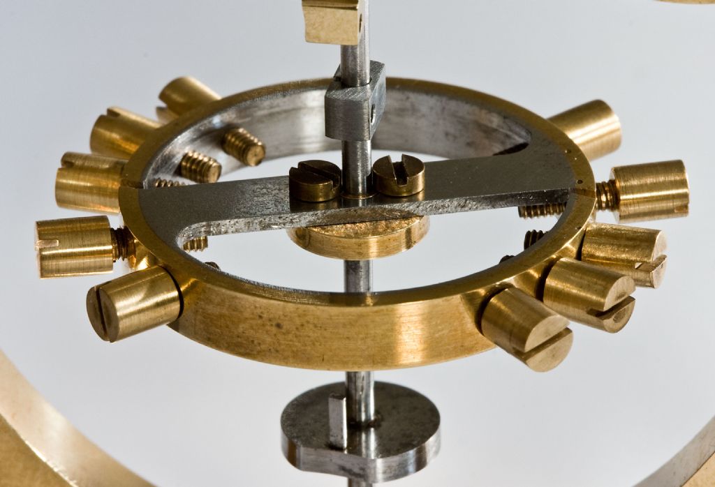 the balance wheel has tiny screws with large heads. These are positioned around the rim, the intention being that they provide a means for time adjustment. To increase the mass of the balance wheel, I slid and glued a brass bush onto the heads of both of the two main adjustment screws, and began a more serious approach to getting the speed correct. With more mass and tweaking of the screws several times per day, I finally achieved an accuracy within three seconds per hour. It ran for about five weeks, with occasional but not yet a full winding. I was therefore satisfied that the clock could be pulled apart for a final scrub up. After more messing about in the garage (I don't have a workshop), I had also made a better-looking spring which I duly fitted as per `the book’ instead of using sewing needles jammed into place. Sourcing some clock oil from a very friendly antique clock restorer in Melbourne, I set the clock ticking.
With (perhaps) an extra turn of wire on the spring, this time the clock was running too slow, so off came the extra mass from the two main screws. They did look a bit clumsy alongside the existing screws. I had also used shellac for the glue, so applying a little heat to each main screw and the weights came loose.
Now the clock was running too fast, but gradual unscrewing of the main screws has produced an accuracy equal to or even better than the previous results. Phew!
Regards to all,
Sam Edited By Sam Stones on 16/09/2011 01:08:31 |
| Richard Parsons | 16/09/2011 06:59:02 |
645 forum posts 33 photos | Sam Hi I have been looking in the wrong books. In ‘Oz’ do you have a Public Library Union? Where you go to your local Public Library and ask for a book, if they have not got it they will then pass the request to the union who will find if any library in the union has a copy. The book I found the solution in is ‘Watch and Clock Making and Repairing by W.J.Gazeley published by Hale ISBN 0-7090-4995-1. I was looking at another book by the same author called ‘Clock and Watch Escapements’. In the first book Gazeley describes two tools for winding balance springs. These are wound 3 of 4 at a time. Each spring is used to make certain that the other springs are correctly spaced. I will PM you a scan of the pages (copy write and all that ‘rhubarb’ You wind in three or four wires unless you will be using ‘Over Coils’ when you only use 2 wires. Remember you do not have to use steel you can use bronze or beryllium copper. Wind your springs and when you have enough turns you tighten down the cover plate to hold everything secure. You then have to ‘set’ springs. You put the winder into an inert atmosphere at about 1500°F (815°C) for 5 minutes. If you are using steel you will need to harden and temper them. You then fill the winder drum up with soft soap secure the cover plate and heat it up to red heat. Quench in water with about 1/8” of oil on the top to reduce thermal shock. To temper, put the whole lot in to a pan with brass turnings and cover with more turnings place a of polished steel on the top. Heat slowly until the polisher steel turns light blue. Remove the barrel and quench immediately. You then have to polish, and flatten your springs Ho Ho what fun! Dick |
| Sam Stones | 16/09/2011 11:37:23 |
922 forum posts 332 photos | Hello again Dick,
I've sent you a PM as requested.
Best regards,
Sam |

 .
. Please login to post a reply.
Magazine Locator
Want the latest issue of Model Engineer or Model Engineers' Workshop? Use our magazine locator links to find your nearest stockist!
Sign up to our Newsletter
Sign up to our newsletter and get a free digital issue.
You can unsubscribe at anytime. View our privacy policy at www.mortons.co.uk/privacy
Latest Forum Posts
- *Oct 2023: FORUM MIGRATION TIMELINE*
05/10/2023 07:57:11 - Making ER11 collet chuck
05/10/2023 07:56:24 - What did you do today? 2023
05/10/2023 07:25:01 - Orrery
05/10/2023 06:00:41 - Wera hand-tools
05/10/2023 05:47:07 - New member
05/10/2023 04:40:11 - Problems with external pot on at1 vfd
05/10/2023 00:06:32 - Drain plug
04/10/2023 23:36:17 - digi phase converter for 10 machines.....
04/10/2023 23:13:48 - Winter Storage Of Locomotives
04/10/2023 21:02:11 - More Latest Posts...
- View All Topics
Support Our Partners


Shopping Partners
Subscription Offer

Latest "For Sale" Ads
- Reeves** - Rebuilt Royal Scot by Martin Evans
by John Broughton
£300.00 - BRITANNIA 5" GAUGE James Perrier
by Jon Seabright 1
£2,500.00 - Drill Grinder - for restoration
by Nigel Graham 2
£0.00 - WARCO WM18 MILLING MACHINE
by Alex Chudley
£1,200.00 - MYFORD SUPER 7 LATHE
by Alex Chudley
£2,000.00 - More "For Sale" Ads...
Latest "Wanted" Ads
- D1-3 backplate
by Michael Horley
Price Not Specified - fixed steady for a Colchester bantam mark1 800
by George Jervis
Price Not Specified - lbsc pansy
by JACK SIDEBOTHAM
Price Not Specified - Pratt Burnerd multifit chuck key.
by Tim Riome
Price Not Specified - BANDSAW BLADE WELDER
by HUGH
Price Not Specified - More "Wanted" Ads...
Get In Touch!
Do you want to contact the Model Engineer and Model Engineers' Workshop team?
You can contact us by phone, mail or email about the magazines including becoming a contributor, submitting reader's letters or making queries about articles. You can also get in touch about this website, advertising or other general issues.
Click THIS LINK for full contact details.
For subscription issues please see THIS LINK.
Digital Back Issues


Donate

 Register
 Log-in
Model Engineer Magazine
- Percival Marshall
- M.E. History
- LittleLEC
- M.E. Clock

ME Workshop
- An Adcock
- & Shipley
- Horizontal
- Mill

Subscribe Now
- Great savings
- Delivered to your door

Pre-order your copy!
- Delivered to your doorstep!
- Free UK delivery!
All Forum Topics > Clocks and Scientific Instruments > My skeleton clock