Forum sponsored by:

Identifying a vintage lathe
| Lee Rogers | 23/09/2022 07:21:27 |
 203 forum posts | The bed is unmistakable Drummond , as for the rest of it a better pic would help.
|
| Nicholas Farr | 23/09/2022 08:21:06 |
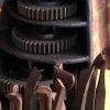
 3988 forum posts 1799 photos | Hi, if you compare these two photos of Haydn's, which I've turned round, they look just like the headstock and tailstock of the picture of the unusual Myford lathe J1102 one that I mentioned in my previous post, even to the saddle rack just extending past the tapered shape of the bed at the tailstock end.
Haydn, the leadscrew is driven by change wheels between the leadscrew end to the left of the clutch lever and the headstock end at the left, the change gears being mounted on pins that fix onto the banjo that swings round at the left of the clutch lever, the change wheels you have do seem to be the correct ones for your machine, but you will probably need a few smaller and larger ones. Regards Nick. P.S. It does look like a Drummond type, but it's not a M type. Edited By Nicholas Farr on 23/09/2022 08:31:05 |
| Ady1 | 23/09/2022 09:24:03 |
 6137 forum posts 893 photos | I think its an M series headstock with parts of the casting hacked/chiselled off and we'll probably have the same sort of damage on the other side where the backgear should be
Edited By Ady1 on 23/09/2022 09:29:39 |
| Haydn Callow | 23/09/2022 09:57:29 |
 64 forum posts 37 photos |
sorry about the inverted photos…working on it.
Edited By SillyOldDuffer on 23/09/2022 12:59:08 |
| Ady1 | 23/09/2022 10:21:19 |
6137 forum posts 893 photos | Yes that picture gave an innacurate bedstock situation Unfortunately I was right about your headstock, it's basically a wood lathe headstock when there's no backgear, slow speed high torque things like thread cutting are far more difficult Nicholas looks right about it's provenance, he's even sawed off part of the rear lug to make that sheet metal cover fit snugly Perhaps the lathe was adapted for woodwork, which is very messy indeed Edited By Ady1 on 23/09/2022 10:27:21 |
| Haydn Callow | 23/09/2022 12:51:46 |
64 forum posts 37 photos | Hi, thanks for all the reply’s., when you say Back gear, do you mean the part with the very large pulley that the motor drives via a V belt and a couple of pulleys that drive the head stock…….I think what’s happened is at some point in its history a very substantial bench has been made for this ( I have it) and the lathe bolts to the bench and then there are all sorts of steel frames that bolt to the back of the bench to carry the motor and back gear.. photos to follow… I’ll try and get them the right way up. |
| Haydn Callow | 23/09/2022 13:03:10 |
64 forum posts 37 photos |
|
| Bazyle | 23/09/2022 13:12:11 |
 6956 forum posts 229 photos | Strictly speaking it isn't a wood lathe headstock just a standard one that has had bits sawn off. - the front part of the backgear guard and the rear arms for the layshaft. Headstocks do appear from time to time on ebay.. You can still get a lot done without backgear and some modern lathes don't have it nor the old Drummond roundbed. |
| SillyOldDuffer | 23/09/2022 13:16:50 |
| 10668 forum posts 2415 photos | Posted by Haydn Callow on 23/09/2022 12:51:46: ... photos to follow… I’ll try and get them the right way up. If you can't fix it by orienting the camera (which doesn't always work as expected), the sure fire method is to edit the image before uploading with a photo-editor. May not be necessary to change anything - just open and save the image - depends on the editor. The underlying problem is digital cameras and software have a number of different ways of deciding orientation and sometimes get confused. Most photo-editors tag the image 'a human said this way up' on save, which is authoritative. With my moderator hat on, I usually rotate obviously wrong photos, but only if I have time to fix the damage if the rotate goes wrong! Every so often rotating messes up the formatting of the whole thread. It's a mystery... Dave
|
| Neil Wyatt | 23/09/2022 13:38:33 |
 19226 forum posts 749 photos 86 articles | Strictly back gear is built into the headstock and uses gears not belts and pulleys. You can use a seperate shaft and pulleys to achieve a similar result. Neil |
| Nigel Graham 2 | 23/09/2022 13:44:51 |
| 3293 forum posts 112 photos | Haydn - "Back-gear" is a low-ratio gearing on the headstock itself, used when extra low spindle speed is necessary, especially in screw-cutting. Only, your lathe has lost it, unless it is all in the assorted bits that came with it. The holes in lugs on the back of the headstock show where it may have been fitted -but the spindle seems to have nowhere for its back-gear wheels. It would show as a large gear on the chuck end of the spindle, and a smaller one at the other end, but both inside the headstock. They would have been matched by two gears on a shaft mounted on rearwards extensions (bolted on, on this machine) of the headstock; with an arrangement for engaging / disengaging them, and for disconnecting the larger spindle-gear from the spindle to allow it to work. . That separate assembly with the pulleys is the Counter-shaft, acting as the primary speed-reduction from the motor, and carrying the speed-change pulleys. With the back-gear lost you could replace it by additional belt-gearing. It would be feasible to make a new back-gear, but not easy, and a lot of work - then you'd need make up a set of change-wheels either with additions fully-compatible with the existing ones, or all-new. Unless you intend cutting many, long, large threads, it is perfectly possible and indeed not unusual, often even advantageous, to do so by slacking the drive-belts and rotating the spindle by hand-crank. Remember to remove the handle before using the motor again! Myfords do sell a mandrel-handle for their lathes but it won't necessarily fit this one. Various designs for making them are in the model-engineering literature, and can be adapted to the specific machine. The basis is an expanding collet a bit like a masonry-bolt. . It is sad to see an old lathe damaged by some previous owner, as appears here. It is very hard to imagine why he removed (and lost?) the back-gear, and cut off that lug on the front of the headstock. If it was to allow fitting a new belt-guard, the motive is good but the method poor! I think the forked lug still at the other end was for a reversing-pinion used when cutting left-hand threads. |
| Haydn Callow | 23/09/2022 16:24:13 |
64 forum posts 37 photos | Nigel, thank you for such a informative reply….I have a Myford ML7 and that is complete….I understand now where and what a back gear is….I doubt I will ever need it…..I bought this lathe as a basket case and I’m hoping to get it sorted over the winter…if I decide to sell it I suppose what has been pointed out will reduce the value….however it came with 3 good chucks, a new half hp motor and other bits….I paid £200 so doubt I’ll lose on it and I may keep it.
|
| Haydn Callow | 23/09/2022 16:27:01 |
64 forum posts 37 photos | I do have the back gear. As said, everything has been modified so it all goes together on the custom made base unit. |
| Ady1 | 23/09/2022 16:43:47 |
6137 forum posts 893 photos | It will still turn stuff ok and you can use the myford for making bits/techie stuff |
| Ady1 | 23/09/2022 17:31:30 |
6137 forum posts 893 photos | I actually retap my Drummonds for metric hex bolts/cap head screws if anything needs done nowadays The holes are all deep and cast iron taps very easily 6mm in the saddle area, 8mm or 10mm would probably do those headstock holes (will take cover in the corner now) |
| Haydn Callow | 23/09/2022 18:53:47 |
64 forum posts 37 photos | That’s exactly what I did this morning, changed the 4 threads that the head stock bolts into….now metric and all good |
| Nigel Graham 2 | 23/09/2022 19:29:09 |
| 3293 forum posts 112 photos | Errr.... why change the threads at all? If the original fasteners are all there and serviceable, and the female threads in the castings have not been badly damaged, there is no need. It is still possible to buy BSW / BSF screws though admittedly not so easily now, and it not that hard to make them! I did so not very long ago to make longer square-headed gib screws for my Drummond shaper, so as to accommodate lock-nuts. The bar stock I used is actually 8mm square but by chance I have an old Thiel machine-tool spanner of that size. Nevertheless I should one day shave the screw-heads down to a Whitworth-size, or at least 5/16" AF, The lock-nuts are of correct BS hexagon. You risk ending up with weakened parts where you have to open the holes up to take a new thread entirely, or weakened "duplex" threads. Even without that you could still then have a machine with a mixture of thread-standards, which is not good. I prefer too, on a vintage machine, to keep as much as possible original; and if making accessories for it, to use compatible threads so I am not having to search two lots of spanners. |
| Haydn Callow | 23/09/2022 20:33:19 |
64 forum posts 37 photos | I’ve sorted the gears out, I have :- 2x30 1x35 1x38 1x45 1x50 1x60 they all have a peg sticking out and a hole so they fit together. non have a cutout for a woodruff key. The end of the lead screw has a woodruff slot so I’m assuming that’s missing. Also missing are the spindles the gears turn on…..anyone out there got a pattern or a drawing / Photo of one? Also the size of the lead screw gear. thanks |
| Nicholas Farr | 23/09/2022 21:18:37 |
3988 forum posts 1799 photos | Hi Haydn, there is a user manual for the Drummond M type Machine Manuals it states all the change gears that were supplied as standard. The one on the leadscrew will depend on what feeds you will require, but it's very often the larger ones. Regards Nick. |
| Nigel Graham 2 | 23/09/2022 22:04:31 |
| 3293 forum posts 112 photos | I don't know how the lead-screw's driving gear is mounted on that particular lathe, but normally it is one of the change-wheels as you have listed above; depending on the screw-thread or fine self-acting feed you select. I've tried a few sample sums with those change-wheels, and assuming an 8TPI lead-screw, but was unable to find combinations of them for more than one or two standard threads; though as you've a Myford lathe presumably you have all its change-wheels so can use that for screw-cutting? 30-idler-45 would give 12TPI. 30-idler-60: 16TPI You can (with their spindles!) make a compound wheel-train and I think the second slot on the arm will allow a third stage, so more threads might be possible. I am not sure about a fine self-acting feed though. I created an 'Excel' spreadsheet to form tables for my EW lathe (25-65 teeth X 5-tooth increments.) If you wanted to add further wheels, I don't know the DP and bores but the pressure-angle might be 14.5º. They would mesh with the more common 20º gears but not very happily, encouraging undue wear. |


Please login to post a reply.
Magazine Locator
Want the latest issue of Model Engineer or Model Engineers' Workshop? Use our magazine locator links to find your nearest stockist!
Sign up to our Newsletter
Sign up to our newsletter and get a free digital issue.
You can unsubscribe at anytime. View our privacy policy at www.mortons.co.uk/privacy
Latest Forum Posts
- hemingway ball turner
04/07/2025 14:40:26 - *Oct 2023: FORUM MIGRATION TIMELINE*
05/10/2023 07:57:11 - Making ER11 collet chuck
05/10/2023 07:56:24 - What did you do today? 2023
05/10/2023 07:25:01 - Orrery
05/10/2023 06:00:41 - Wera hand-tools
05/10/2023 05:47:07 - New member
05/10/2023 04:40:11 - Problems with external pot on at1 vfd
05/10/2023 00:06:32 - Drain plug
04/10/2023 23:36:17 - digi phase converter for 10 machines.....
04/10/2023 23:13:48 - More Latest Posts...
- View All Topics
Support Our Partners


Shopping Partners
Subscription Offer

Latest "For Sale" Ads
- Reeves** - Rebuilt Royal Scot by Martin Evans
by John Broughton
£300.00 - BRITANNIA 5" GAUGE James Perrier
by Jon Seabright 1
£2,500.00 - Drill Grinder - for restoration
by Nigel Graham 2
£0.00 - WARCO WM18 MILLING MACHINE
by Alex Chudley
£1,200.00 - MYFORD SUPER 7 LATHE
by Alex Chudley
£2,000.00 - More "For Sale" Ads...
Latest "Wanted" Ads
- D1-3 backplate
by Michael Horley
Price Not Specified - fixed steady for a Colchester bantam mark1 800
by George Jervis
Price Not Specified - lbsc pansy
by JACK SIDEBOTHAM
Price Not Specified - Pratt Burnerd multifit chuck key.
by Tim Riome
Price Not Specified - BANDSAW BLADE WELDER
by HUGH
Price Not Specified - More "Wanted" Ads...
Get In Touch!
Do you want to contact the Model Engineer and Model Engineers' Workshop team?
You can contact us by phone, mail or email about the magazines including becoming a contributor, submitting reader's letters or making queries about articles. You can also get in touch about this website, advertising or other general issues.
Click THIS LINK for full contact details.
For subscription issues please see THIS LINK.
Digital Back Issues


Donate

 Register
 Log-in
Model Engineer Magazine
- Percival Marshall
- M.E. History
- LittleLEC
- M.E. Clock

ME Workshop
- An Adcock
- & Shipley
- Horizontal
- Mill

Subscribe Now
- Great savings
- Delivered to your door

Pre-order your copy!
- Delivered to your doorstep!
- Free UK delivery!
All Forum Topics > Help and Assistance! (Offered or Wanted) > Identifying a vintage lathe