Forum sponsored by:

Adaptation of the Proxxon Milling machine
| Graham Meek | 15/10/2022 14:49:41 |
| 714 forum posts 414 photos | Posted by Jamie Wood on 15/10/2022 12:35:34:
Very interesting work Gray. I have recently bought a Proxxon column assembly from a PF400 that I plan to use to improve the rigidity/usability of my C5 mill somewhat. The new column, at 45mm is 10mm thicker than the Emco and has the benefit of keyed clamping block and Z leadscrew. After reading this I will definitely be checking the accuracy of my parts before I start making a new mounting clamp/base. Your new X/Y scales look great as well, the stops are a nice addition. Do you think you might ever try to fit some digital ones on there? I just about managed to squeeze some onto my C5 table, although with the new column they may need some adjustment Jamie Hello Jamie, Glad you like my old school scales. I had hoped to purchase a good FF400 mill when I was looking around for a replacement for my FB2. Unfortunately these are like Hen's teeth. It would have matched the C5 capacity better. I did consider at the outset fitting digital scales, especially as my memory is not so good these days. Upon checking the clearances under the table feed unit this was not going to be that easy. Plus the reading heads on the scales looked totally out of proportion on this machine. This coupled with my planned usage these days I could no justify the expense. I would still have needed to put some form of bar on the machine to carry the table stops. What are you intending to do with the C5 Milling head? Regards Gray,
|
| Jamie Wood | 21/10/2022 11:45:38 |
| 19 forum posts 8 photos | Hi Gray, That's fair enough, it was a tight squeeze getting the digital scales on the C5 table, in fact I didn't account for one of the reader box parts just clipping the column mount, and thus lost a bit of Y travel, which is part of the reason for this column replacement. I've actually been thinking of wiring them up to a tablet using touchDRO to get some of the extra benefits of 'proper' DROs. Sorry to get your hopes up, but I only have the Proxxon column and column clamp, so I'll still be using the C5 head but adapted to fit this. It may end up looking a bit clunky, but as long as it improves the milling capabilities! Maybe I'll have to start my own thread on here to document in case anyone else is interested. Thanks, Jamie
|
| Graham Meek | 21/10/2022 14:01:43 |
| 714 forum posts 414 photos | Hi Jamie, Sorry I misunderstood your post. I thought you had the Proxxon head as well. This has a better speed range than the C5 and that range is also better than the milling head on my mill. The fact you can mount cutters directly in the spindle is a big bonus with these machines. That is not such a bad idea about the thread showing your mods. Regards Gray, |
| Dick H | 21/12/2022 17:15:33 |
| 141 forum posts 1 photos | I have a Proxxon FF230 mini (nano?) mill, Can someone please tell me how to remove the stepped pulley at the top of the spindle? There is a very small grub screw to be removed and then I assumed the pulley should be able to be pulled off. Am I missing something? Is it screwed on or has someone used a locking compound on the shaft? I don´t want to use too much umph on it. Dick. |
| Bountyboy | 21/12/2022 17:47:07 |
| 62 forum posts 8 photos | Fabulous work Gray, a life time of refining your design and machining skills. I’ve just purchased your book, Projects for your workshop, from RDG (early Christmas present). Hoping to make the spindle lock for the EMCO FB2. Looking forward to seeing more workshop wizardry! |
| Graham Meek | 24/12/2022 15:09:37 |
| 714 forum posts 414 photos | Posted by Dick H on 21/12/2022 17:15:33:
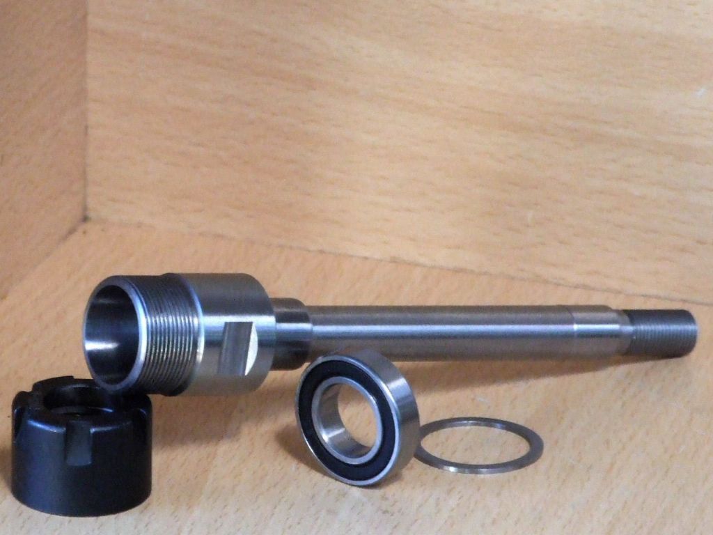
I have a Proxxon FF230 mini (nano?) mill, Can someone please tell me how to remove the stepped pulley at the top of the spindle? There is a very small grub screw to be removed and then I assumed the pulley should be able to be pulled off. Am I missing something? Is it screwed on or has someone used a locking compound on the shaft? I don´t want to use too much umph on it. Dick. Hello Dick, My apologies for not responding sooner. The Pulley unscrews once you have removed the M3 grubscrew. You will need a Peg spanner to go in the two holes in the pulley. I made mine from a short piece of aluminium bar and two short lengths of silver steel. When replacing the pulley do not over tighten the grubscrew or the pulley will wobble. Also bear in mind that this pulley also adjusts bearing pre-load which does not want to be excessive. Just enough to eliminate any endwise play. When I made the new ER 20 spindle for my Proxxon I altered this design. I introduced a separate circular nut. This nut adjusts the bearings while the Pulley locks the adjustment and the assembly. I hope in due course to publish details on this mod, as well as the spindle mod. Regards Gray, |
| Dick H | 24/12/2022 16:14:57 |
| 141 forum posts 1 photos | Many thanks. I couldn´t see from the exploded diagram what was going on. I´ll have another go over Christmas. Regards, Dick |
| Graham Meek | 24/12/2022 19:32:07 |
| 714 forum posts 414 photos | Hello Dick, I forgot to mention Proxxon have started using Loctite Thread Locking compound in more recent times. Regards Gray, |
| Dick H | 24/12/2022 21:15:41 |
| 141 forum posts 1 photos | It is at least 15 years old, so i hope not, else I'll have to get a flame to it. Thanks again. Dick. |
| Graham Meek | 14/01/2023 17:28:07 |
| 714 forum posts 414 photos |
The Mounting Board for the Proxxon mill has finally been fitted. The Switch and Knob are for the variable power feed. This now has a dedicated 12v Power Supply feeding a PWM unit. While I have more variation of the feed rate lower down with this set-up. It has been at the expense of a reduced top feed rate. However due to use of the Proxxon plug arrangement on the table feed motor. It is still possible to substitute the Proxxon power supply if needed, so I have the best of both worlds.
Talking to a friend recently I was saying I was making a milling machine vice stop for the Proxxon mill. My listener was not familiar with this term or set-up. These type of stops are used widely in industry and I have used countless hundreds in my career. Up until I had completed this unit I had been managing to do jobs with a stop mounted in the tee-slot off the milling table. However the manufacture of the Table Protectors to help keep the table clear of swarf made using this type of stop a nuisance. Plus when using the vice as shown above there is no Tee slot to use such a stop.
This view shows the construction of the table protectors and the stowing position for the stop when this is not being used. The spigot positions are such that the protectors will also fit across the table when using the Emco Compact 5 rotary table. The Acrylic is Yellowish and it is not the camera. This was some off-cuts I had left over from an assembly tool which used UV light and this particular Acrylic blocked the UV. Regards Gray, |
| Graham Meek | 17/02/2023 16:09:05 |
| 714 forum posts 414 photos |
A while back in this thread I had to use my smaller Boring head to extend the range of my Boring and Facing head. A set-up which I was not impressed with, but it did do the job. I have since made a dedicated Extender block for the B&F Head, shown above. Those Eagle Eyed among you might notice the two dowels in the Gib strip. This forms part of a further refinement for this machine and I will shortly post more details about this. Regards Gray, |
| Graham Meek | 18/02/2023 15:18:10 |
| 714 forum posts 414 photos |
I did think when I purchased this machine, given it's country of origin. That I would not have a lot to do to get this machine to where I wanted it. The Guide strip or Key down the Column was one area I thought would not need any attention. Unfortunately this time I was wrong. The Guide strip is held onto the Column with countersunk Allen cap screws. Experience has told me that the heads on these screws are seldom concentric with the thread. The head will therefore tend to move sideways the item being secured. This was one of the issues with this machine. While the Guide strip was relatively straight, 0.05 mm bend over the 290 mm. When fitted to the Column there was helical run-out of around 0.2 mm from end to end. Straightening the Guide strip 0.005 mm over the 290 mm and counterboring the countersunk holes to take shallow head M3 cap screws, eradicated the helical error. To make sure the Guide strip did not move during use four 2.5 mm hardened dowels were fitted at 90 mm centres. In the above photograph you will see two additional M5 cap screws have been added to adjust the clearance between the Column and the Slider. Next to these is a large slotted screw head. This carries an eccentrically mounted ball bearing race which eliminates the play between the Slider and the Guide strip.
This shot shows the bearing just showing in the sidewall of the keyway. Note there is no loss of bearing area on the internal surface of the Slider to Column interface.
These are the adjuster parts and wiper assembly to keep swarf out. The Allen key is in an M4 grubscrew which locks the eccentric adjuster via a copper pad.
This shows the basic modifications . The two tapped holes on the top of the Slider are to lock the M5 cap screws after adjustment. There is a Delrin pad beneath the M4 grubscrews.
These modifications have totally transformed the machine in use and have been well worth the extra work. There is one more small mod which I will detail later. Regards Gray, |
| duncan webster | 18/02/2023 23:37:07 |
| 5307 forum posts 83 photos | Just a caution, I bought 2 of those little Swan neck lights, but I've binned them. They have a capacitor to limit the current, but the plug wasn't handed, so the 240v could easily be applied to one end of the leds via a very thin wire inside the metal neck. No earth, no double insulation. Potentially deadly |
| Graham Meek | 19/02/2023 11:11:13 |
| 714 forum posts 414 photos | Hi Duncan, I have three such lights in use and as yet I have not had any problem with them. These lights came with a slotted tag on both wires which were the same colour. It is not my final answer to the lighting problem as I does leave a unlit area the other side. I also have to watch how bright a light I use. Too much brightness will induce a migraine. Halo type lights are too bright having tried these. Regards Gray, |
| Graham Meek | 19/02/2023 15:24:44 |
| 714 forum posts 414 photos |
One thing I had noticed when "Tramming" the milling head was that there was a tendency for the Quill housing to work it's way out of the Slider. To solve this I have made a semicircular Bronze Key which fits in the groove machined to provide clearance for the M6 Cap screw which clamps everything up when the Milling head is dead true. The key is held in place with a single M4 Cap screw. The counterbore for this can be seen in the top face of the Slider.
The Bronze ring provided two Keys which was handy as I have a spare milling head. One other thing I need to make is a Tailstock support for the Emco Dividing attachment which I have adapted to fit this machine. This will then give me the machine that I want. Regards Gray, |
| Ian P | 19/02/2023 16:27:19 |
 2747 forum posts 123 photos | Posted by duncan webster on 18/02/2023 23:37:07:
Just a caution, I bought 2 of those little Swan neck lights, but I've binned them. They have a capacitor to limit the current, but the plug wasn't handed, so the 240v could easily be applied to one end of the leds via a very thin wire inside the metal neck. No earth, no double insulation. Potentially deadly Duncan, I dont want to take Grahams thread too far off topic but from your description those work lights should not be on sale in the UK. From the descriptions of the ones being sold on ebay and Amazon I would have assumed that there was a proper SMPS in the magnetic base, if its just a capacitor dropper than I'm appalled! Please can you confirm if that the case? In any event the ones I have seen are being marketed with a USA 2 pin plug so the product is wrong on several levels. But they look downright dangerous. Ian P |
| Graham Meek | 19/02/2023 16:42:05 |
| 714 forum posts 414 photos | Hi Ian P, I can tell you there is a circular populated Circuit board contained in the plastic cylindrical housing. I cannot say for sure how many components are present. Regards Gray, |
| Ian P | 19/02/2023 17:02:30 |
2747 forum posts 123 photos | Its quite possible that the PCB contains an PSU with an isolated output but in one sense its irrelevant as almost certainly it will not be compliant with UK regs. I know you have the lights fitted to a machine and in use, so please be careful, I suggest finding some way of adding a ground wire to metal flexy bit. This comes up on Google __________________________________________________________________________________________ The three-pin/two-pin plug problem also arises if you're a UK retailer or distributor selling devices manufactured in Europe that come to you with a two-pin connector attached. UK law insists that all European electrical products must be converted to a three-pin UK plug before sale or distribution. Ian P |
| duncan webster | 19/02/2023 20:26:54 |
| 5307 forum posts 83 photos | As I said I've binned mine. No switch mode, capacitor. Bought direct from China, not UK stock. You won't know you've got a problem until you're twitching on the floor. |
| Kiwi Bloke | 20/02/2023 00:30:45 |
| 912 forum posts 3 photos | Gray. Interesting mod, that can be applied to other machines, of course, and beautifully executed, as we've come to expect. Two questions... 1. Why did you choose to use a roller (ball bearing set) to follow the guidance strip/key, rather than fit a gib strip? 2. (Apologies if I've overlooked the answer). Is the column's guide strip/key located in a groove in the column, or just planted on its surface, or on a flat? |


Please login to post a reply.
Magazine Locator
Want the latest issue of Model Engineer or Model Engineers' Workshop? Use our magazine locator links to find your nearest stockist!
Sign up to our Newsletter
Sign up to our newsletter and get a free digital issue.
You can unsubscribe at anytime. View our privacy policy at www.mortons.co.uk/privacy
Latest Forum Posts
- hemingway ball turner
04/07/2025 14:40:26 - *Oct 2023: FORUM MIGRATION TIMELINE*
05/10/2023 07:57:11 - Making ER11 collet chuck
05/10/2023 07:56:24 - What did you do today? 2023
05/10/2023 07:25:01 - Orrery
05/10/2023 06:00:41 - Wera hand-tools
05/10/2023 05:47:07 - New member
05/10/2023 04:40:11 - Problems with external pot on at1 vfd
05/10/2023 00:06:32 - Drain plug
04/10/2023 23:36:17 - digi phase converter for 10 machines.....
04/10/2023 23:13:48 - More Latest Posts...
- View All Topics
Support Our Partners


Shopping Partners
Subscription Offer

Latest "For Sale" Ads
- Reeves** - Rebuilt Royal Scot by Martin Evans
by John Broughton
£300.00 - BRITANNIA 5" GAUGE James Perrier
by Jon Seabright 1
£2,500.00 - Drill Grinder - for restoration
by Nigel Graham 2
£0.00 - WARCO WM18 MILLING MACHINE
by Alex Chudley
£1,200.00 - MYFORD SUPER 7 LATHE
by Alex Chudley
£2,000.00 - More "For Sale" Ads...
Latest "Wanted" Ads
- D1-3 backplate
by Michael Horley
Price Not Specified - fixed steady for a Colchester bantam mark1 800
by George Jervis
Price Not Specified - lbsc pansy
by JACK SIDEBOTHAM
Price Not Specified - Pratt Burnerd multifit chuck key.
by Tim Riome
Price Not Specified - BANDSAW BLADE WELDER
by HUGH
Price Not Specified - More "Wanted" Ads...
Get In Touch!
Do you want to contact the Model Engineer and Model Engineers' Workshop team?
You can contact us by phone, mail or email about the magazines including becoming a contributor, submitting reader's letters or making queries about articles. You can also get in touch about this website, advertising or other general issues.
Click THIS LINK for full contact details.
For subscription issues please see THIS LINK.
Digital Back Issues


Donate

 Register
 Log-in
Model Engineer Magazine
- Percival Marshall
- M.E. History
- LittleLEC
- M.E. Clock

ME Workshop
- An Adcock
- & Shipley
- Horizontal
- Mill

Subscribe Now
- Great savings
- Delivered to your door

Pre-order your copy!
- Delivered to your doorstep!
- Free UK delivery!
All Forum Topics > Manual machine tools > Adaptation of the Proxxon Milling machine