Forum sponsored by:

Stuart #1 Reverse Drawings
| John Purdy | 18/02/2022 18:25:48 |
 431 forum posts 252 photos | Noel I sent a msg. back to Stuart Models thanking them for their reply and included the following statement: "If the drawing was amended to show the boss on the reverse lever to be 1/4" wide (vice 3/32" ) and not the width across the whole reverse lever this would solve the problem. Either that or a note with the drawings specifying a 5/32" wide spacer between the reverse shaft and the support bracket boss." We'll see how they respond. John
Edited By John Purdy on 18/02/2022 18:26:23 |
| JasonB | 18/02/2022 18:40:57 |
 25215 forum posts 3105 photos 1 articles | The longer boss would look the nicest of the two |
| John Purdy | 18/02/2022 18:45:07 |
431 forum posts 252 photos | Agreed. But that would mean a re-draw of the plans. We'll see how they respond! I've just checked the reverse lever casting in my 5A reverse gear set ( they both use the same one, also the same expansion link casting ) and I don't think the boss is long enough as cast to make it 1/4" and keep the turned handle at the end centred on the shaft. John Edited By John Purdy on 18/02/2022 18:51:30 |
| JasonB | 18/02/2022 19:29:00 |
25215 forum posts 3105 photos 1 articles | Be easier to supply a bit of steel bar |
| John Purdy | 18/02/2022 19:52:10 |
431 forum posts 252 photos | Just add a 1/4" or so to the 1/2"dia. x1 3/4" long steel supplied for the reverse lever anchor screw and nut. John |
| John Purdy | 18/02/2022 23:43:06 |
431 forum posts 252 photos | Just out of curiosity I got out the plans for the #5A and its reverse gear, and added up the dimensions to see if the reverse gear expansion link and valve rod line up on it. No problem with this one, everything lines up. John |
| JasonB | 19/02/2022 06:59:43 |
25215 forum posts 3105 photos 1 articles | Sounds like they use the same castings and drawings for both but should have altered the drawings for the No1. If they did not want to do a whole new drawing adding a detail for the No1 lever would not be hard to do or use an errata sheet as they do with other models though that can get lost! J PS I was thinking of square or rect bar to make a whole lever from, infact it could all be cut from solid and unlikely on full size engines to have been cast. Bracket would be the exception but even that is not hard to cut from solid and I'd probably change the width of the part that goes against the chest as I don't like how it partly overlaps the cover. |
| David Senior | 19/02/2022 08:18:01 |
| 30 forum posts 8 photos | I've followed this thread with interest - I'm working on a 5A with reversing gear at the moment, and if I've got it right the eccentrics foul the step in the crankshaft. On nominal dimensions the eccentrics will rub on the flange of the crank bearing, but the crank change in diameter is a further 1/16" out. The additional drawing for the reversing gear shows a clearance of about 1/16" between the eccentrics and the bearing flange. (My drawings are dated 1954 and issued in 1965 - the engine was started by my grandfather who died in 1966 and I feel it is about time it was finished!) Dave |
| John Purdy | 19/02/2022 19:22:29 |
431 forum posts 252 photos | Dave
Edited By John Purdy on 19/02/2022 19:27:47 |
| JasonB | 19/02/2022 20:10:28 |
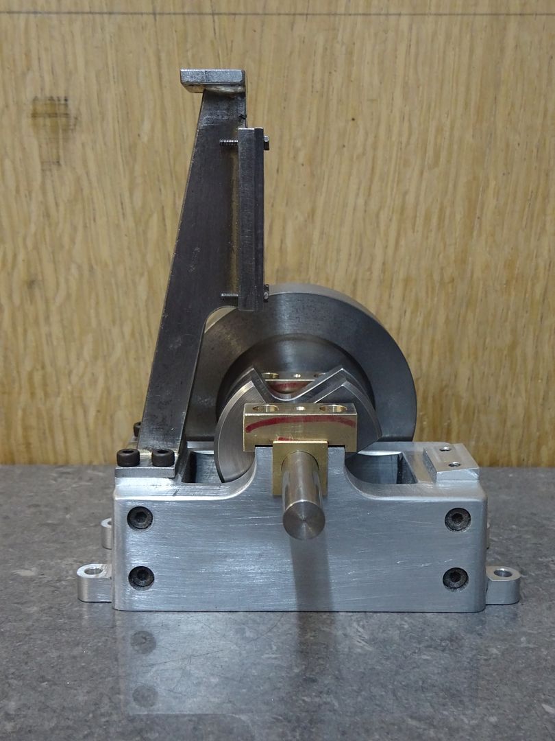
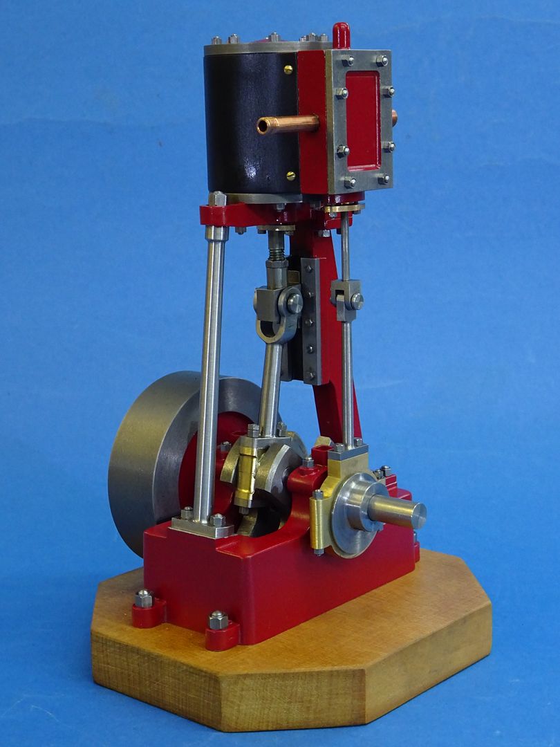
25215 forum posts 3105 photos 1 articles | If all else fails it should not be hard to fabricate abase that looks like a casting, this is one I drew up for someone who was missing it from some 10V parts they had
Built up in a similar way to this one of mine
Who's to know what's under the paint
|
| John Purdy | 19/02/2022 20:37:31 |
431 forum posts 252 photos | Jason When I said in my previous post "just add 1/4" to the 1/2" dia. - - - - " I was thinking you were talking about the spacer not the whole lever but making the whole reverse lever out of the solid would certainly be a possible solution. Wouldn't actually be much harder as the casting (which is malleable iron and machines pretty much like steel anyway ) needs to be machined all over. As far as fabricating the bed plate for the 5A, that's definitely possible but where I live it is next to impossible to get raw materials. John |
| David Senior | 19/02/2022 21:59:31 |
| 30 forum posts 8 photos | John Thanks for taking the trouble to check your drawings My belief is that the bearings need to be fitted with the thin flange inwards, and the thick one outwards (crank width across webs = 1 7/8", Gap in bed plate = 2 1/4" leaving space for bearing flanges of 3/8" i.e. 2 at 3/16" So my calculation for bed plate centreline to bearing outer face is 1 1/8" + 3/4" + 5/16" = 2 3/16" I agree with the 2 9/16" to the centreline of the valve rod The eccentrics are a total of 3/4" wide, so half of that (3/8" The crank bearing diameter extends to 15/16" + 1 5/16" from the centreline (2 1/4" If I am correct I will need to either shorten the bearing diameter on that side of the crank or (more likely) counterbore the eccentric pair to clear the step on the shaft. Skimming a small amount off the main bearing on that side to give a small clearance should be straightforward. I haven't checked with Stuart Models as to whether the drawings have been changed, so I don't know whether this is a recognised problem (or whether I am somewhere mistaken) I am impressed with the look and finish of your No1 - I can only hope that my 5A will be somewhere near and that my grandfather would have been proud of it. Dave |
| John Purdy | 20/02/2022 00:07:18 |
431 forum posts 252 photos | Dave You are right, the bearings have to be mounted with the 3/16 flange inboard. I was using the bearings with the 3/16 flange out as that what it looked like on the reverse drawings. Should have checked the crank/ bearing/bed opening, duh! With the bearings the right way I get the clearances as: Bed plate centre line to bearing outer face now 2 3/16" Therefore valve rod centre line to bearing face now 3/8" The way I calculated the valve rod centre line on the eccentric rod to the sheave face was: the ears on eccentric rod fork are (1/2"-9/32" )/2 = 7/64" wide, therefore centre line of fork is 7/64+9/64 from face of rod in slot in the strap, the edge of the slot is 1/8" from the face of the strap, the sheave is 3/8" wide, but the strap is 11/32" wide therefore the sheave extends out beyond the strap by 1/64", for a total distance fork centre line to sheave face of 7/64 +9/64+1/8+1/64 = 25/64 (.390 ) resulting in the sheave face being .015" into the bearing for things to line up. This doesn't take into consideration the 1/16" extension of the crank dia beyond the bearing face. So it sounds like to make things line up the bearing face will have to be skimmed and the sheave counterbored for the crank unless we're both missing something! So as you had initially found there seems to be a problem. Sorry for me confusing things. Interesting that both the #1 and the #5 reverse gear have problems Thanks for the kind comments on my engine. John |
| David Senior | 20/02/2022 10:13:01 |
| 30 forum posts 8 photos | John I think you have missed the fact that the strap is not symmetrical about the locating groove. By my calculation (and as shown visually on the reverse gear drawing - not that that should be taken as gospel!) the straps align with the outer faces of the eccentrics, leaving a gap between the straps. This doesn't change your conclusion, except that the skimming of the bearing face will only be to give working clearance, rather than to correct a foul. The eccentric pair will definitely need counterboring to clear the crankshaft bearing diameter. I have yet to attempt to master the joys of tapered gib keys. Clearly here it is going to be important that the key doesn't protrude beyond the eccentrics. I think we are there now! Dave |
| John Purdy | 20/02/2022 18:21:15 |
431 forum posts 252 photos | Dave Your right again! I missed the groove in the eccentric strap being offset so the face is flush with the sheave. So ignore the extra 1/64" in my previous. Is there any reason why the larger dia. on the crank has to extend out beyond the bearing? I'd be curious to know how you machined the eccentric pair. I've looked at it a couple of times and tried to visualize how to machine it but haven't had much success. John |
| David Senior | 20/02/2022 19:05:03 |
| 30 forum posts 8 photos | John There is no reason that I can think of for having the shaft longer, apart from not wanting it to be shorter than the bearing so that it can't wear a groove in the bearing. So I guess equal or just slightly longer would be best. I haven't got to making the eccentrics yet, but I am thinking of doing the bore and keyway first, then mounting on a mandrel with both centres in the ends so that I can set between centres to machine. I intend to machine them to the same width as the straps, so there will be a section between them that looks like a woodworking biscuit joint piece, if that makes sense. That way it is not so critical about getting the 'joint' in the middle. Not sure when I will get round to it. Technically I retired at the end of Jan, which is why I have started on this project. However retirement for me will be going to work everyday as normal (all my equipment is there) and hopefully not having to do any 'proper' work so that I can concentrate on the models. Right now I am still choosing to run cnc machines until a new employee starts in a fortnight, so I am not able to concentrate fully on this. Dave |
| John Purdy | 20/02/2022 20:09:01 |
431 forum posts 252 photos | Dave If you have access to it, I just remembered that there was a series in Engineering in Miniature by Andrew Smith on building the ST Cygnet (basically a #5A ). I have dug it out and it ran from May '81 to Dec '83. In one of the installments he details a method of machining of the double eccentric, also an alternative. On a totally different note, I don't know if you are aware, but you can prevent the "smlies" showing up at the end of a bracketed statement by putting a space before the final bracket. John Edited By John Purdy on 20/02/2022 20:10:48 Edited By John Purdy on 20/02/2022 20:16:30 |
| John Purdy | 20/02/2022 20:50:31 |
431 forum posts 252 photos | Dave I've sent you a PM. John |

 inboard of the valve rod gives 2 9/16" - 3/8" = 2 3/16" so nominally touching the bearing face.
Please login to post a reply.
Magazine Locator
Want the latest issue of Model Engineer or Model Engineers' Workshop? Use our magazine locator links to find your nearest stockist!
Sign up to our Newsletter
Sign up to our newsletter and get a free digital issue.
You can unsubscribe at anytime. View our privacy policy at www.mortons.co.uk/privacy
Latest Forum Posts
- *Oct 2023: FORUM MIGRATION TIMELINE*
05/10/2023 07:57:11 - Making ER11 collet chuck
05/10/2023 07:56:24 - What did you do today? 2023
05/10/2023 07:25:01 - Orrery
05/10/2023 06:00:41 - Wera hand-tools
05/10/2023 05:47:07 - New member
05/10/2023 04:40:11 - Problems with external pot on at1 vfd
05/10/2023 00:06:32 - Drain plug
04/10/2023 23:36:17 - digi phase converter for 10 machines.....
04/10/2023 23:13:48 - Winter Storage Of Locomotives
04/10/2023 21:02:11 - More Latest Posts...
- View All Topics
Support Our Partners


Shopping Partners
Subscription Offer

Latest "For Sale" Ads
- Reeves** - Rebuilt Royal Scot by Martin Evans
by John Broughton
£300.00 - BRITANNIA 5" GAUGE James Perrier
by Jon Seabright 1
£2,500.00 - Drill Grinder - for restoration
by Nigel Graham 2
£0.00 - WARCO WM18 MILLING MACHINE
by Alex Chudley
£1,200.00 - MYFORD SUPER 7 LATHE
by Alex Chudley
£2,000.00 - More "For Sale" Ads...
Latest "Wanted" Ads
- D1-3 backplate
by Michael Horley
Price Not Specified - fixed steady for a Colchester bantam mark1 800
by George Jervis
Price Not Specified - lbsc pansy
by JACK SIDEBOTHAM
Price Not Specified - Pratt Burnerd multifit chuck key.
by Tim Riome
Price Not Specified - BANDSAW BLADE WELDER
by HUGH
Price Not Specified - More "Wanted" Ads...
Get In Touch!
Do you want to contact the Model Engineer and Model Engineers' Workshop team?
You can contact us by phone, mail or email about the magazines including becoming a contributor, submitting reader's letters or making queries about articles. You can also get in touch about this website, advertising or other general issues.
Click THIS LINK for full contact details.
For subscription issues please see THIS LINK.
Digital Back Issues


Donate

 Register
 Log-in
Model Engineer Magazine
- Percival Marshall
- M.E. History
- LittleLEC
- M.E. Clock

ME Workshop
- An Adcock
- & Shipley
- Horizontal
- Mill

Subscribe Now
- Great savings
- Delivered to your door

Pre-order your copy!
- Delivered to your doorstep!
- Free UK delivery!
All Forum Topics > Stationary engines > Stuart #1 Reverse Drawings