Forum sponsored by:

A Lightweight Husky
| JasonB | 06/12/2021 19:21:31 |
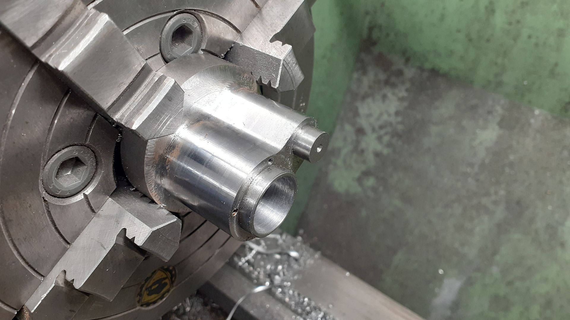
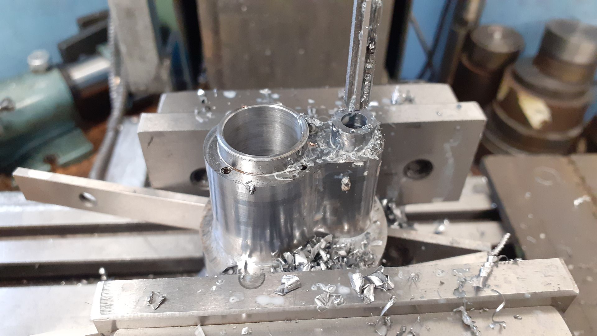
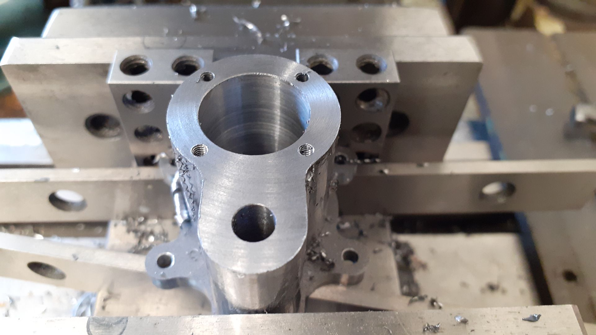
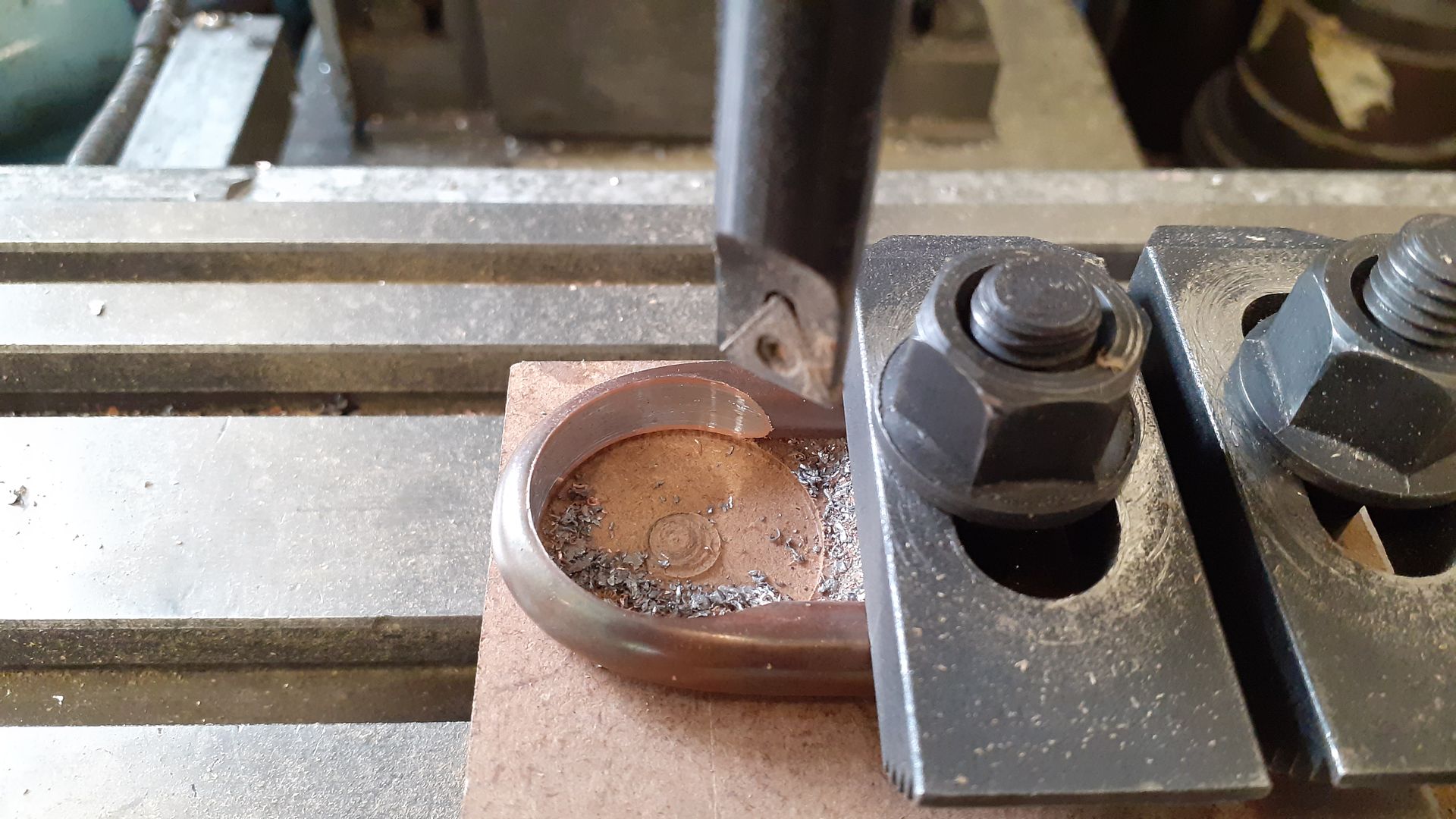
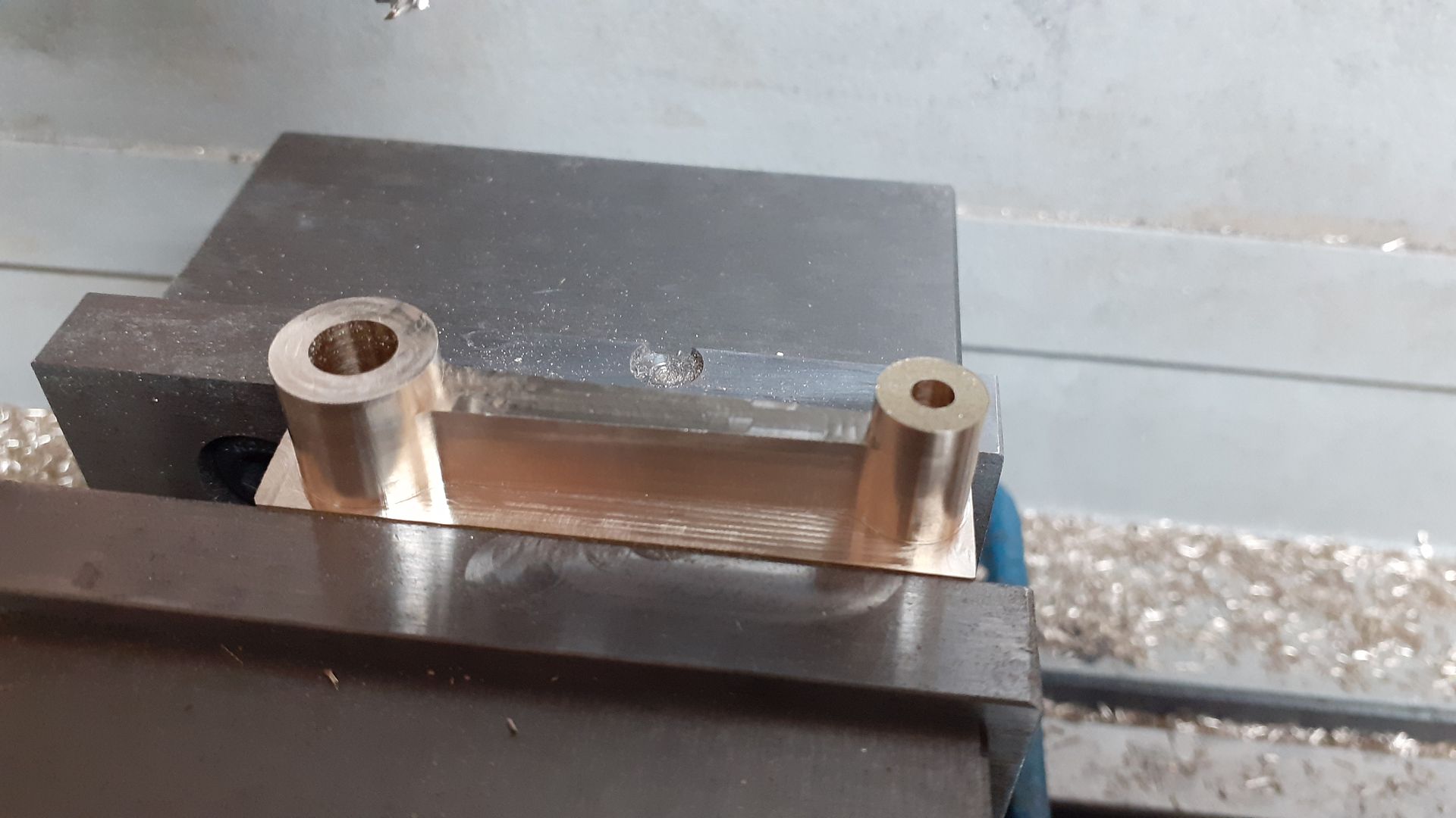
 25215 forum posts 3105 photos 1 articles | All interesting stuff, I may have a play with the moving bits at some time to see if I can tame it's down a bit but as I have just got some measurements of the next one in the series will probably concentrate on that instead. I was in two minds as to what to make the cylinder from. Cast iron would have been nice but not so easy to solder the exhaust to it, Bronze and brass would have been easy to solder but it's a bit of a lump and I did not have much suitable in stock (at least that I wanted to cut into) so I ended up going for 230M07 (EN1A) as it's not really any more likely to rust than iron particularly as I'm mostly going to run on air.
|
| JasonB | 08/12/2021 16:32:47 |
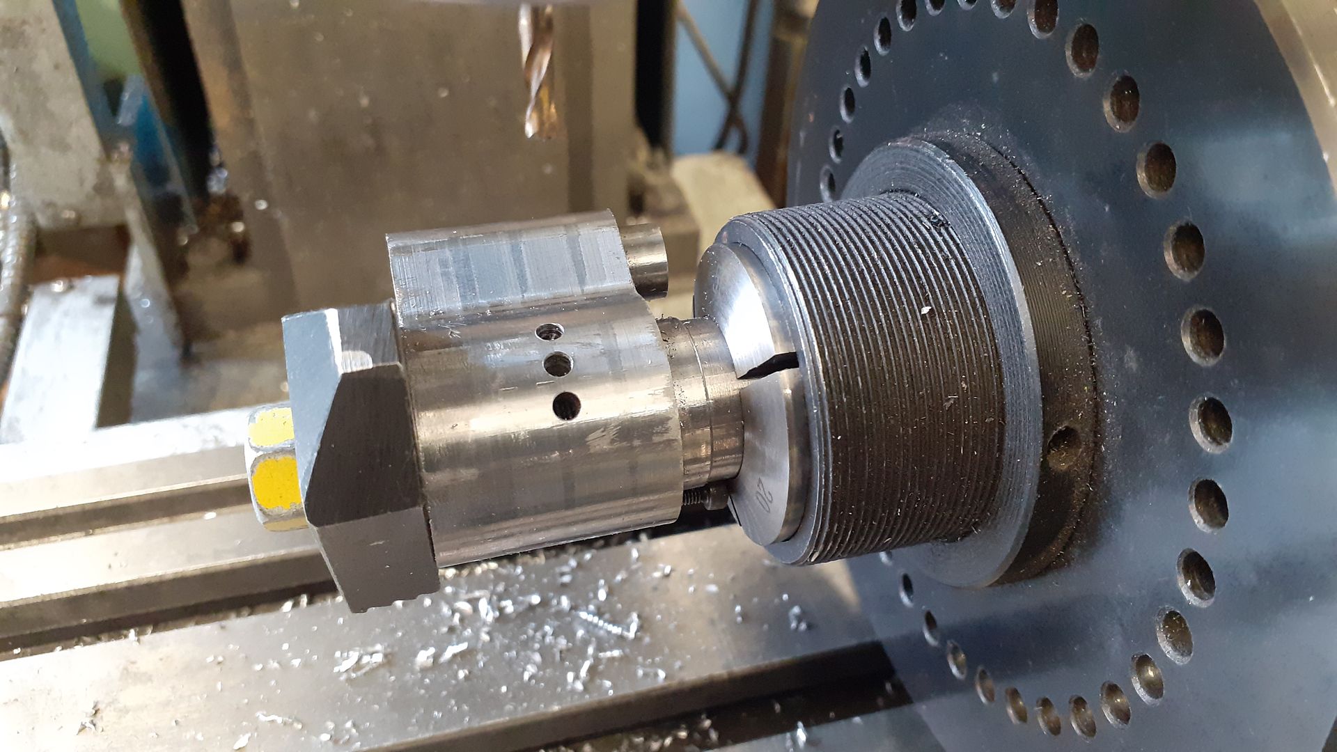
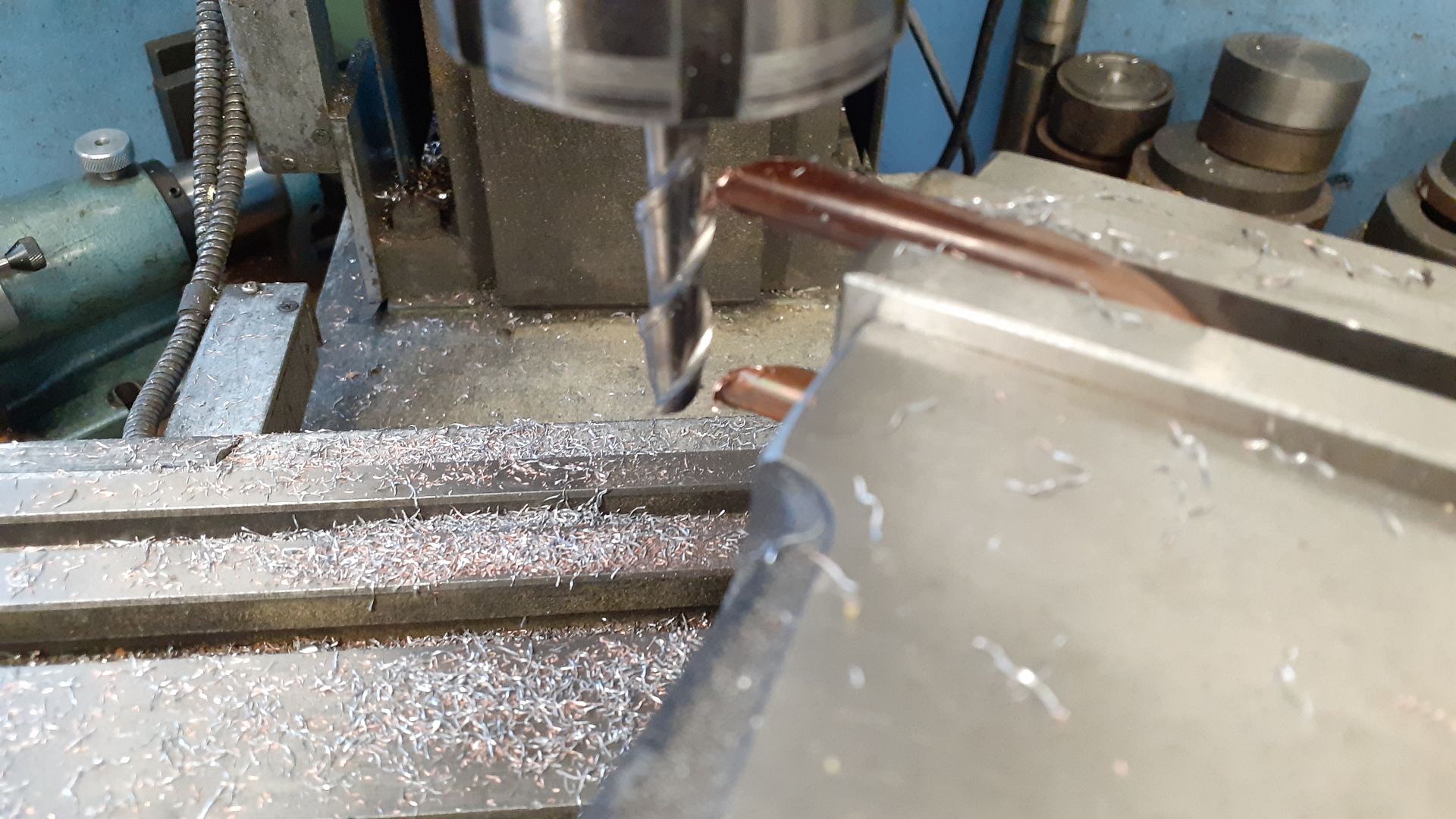
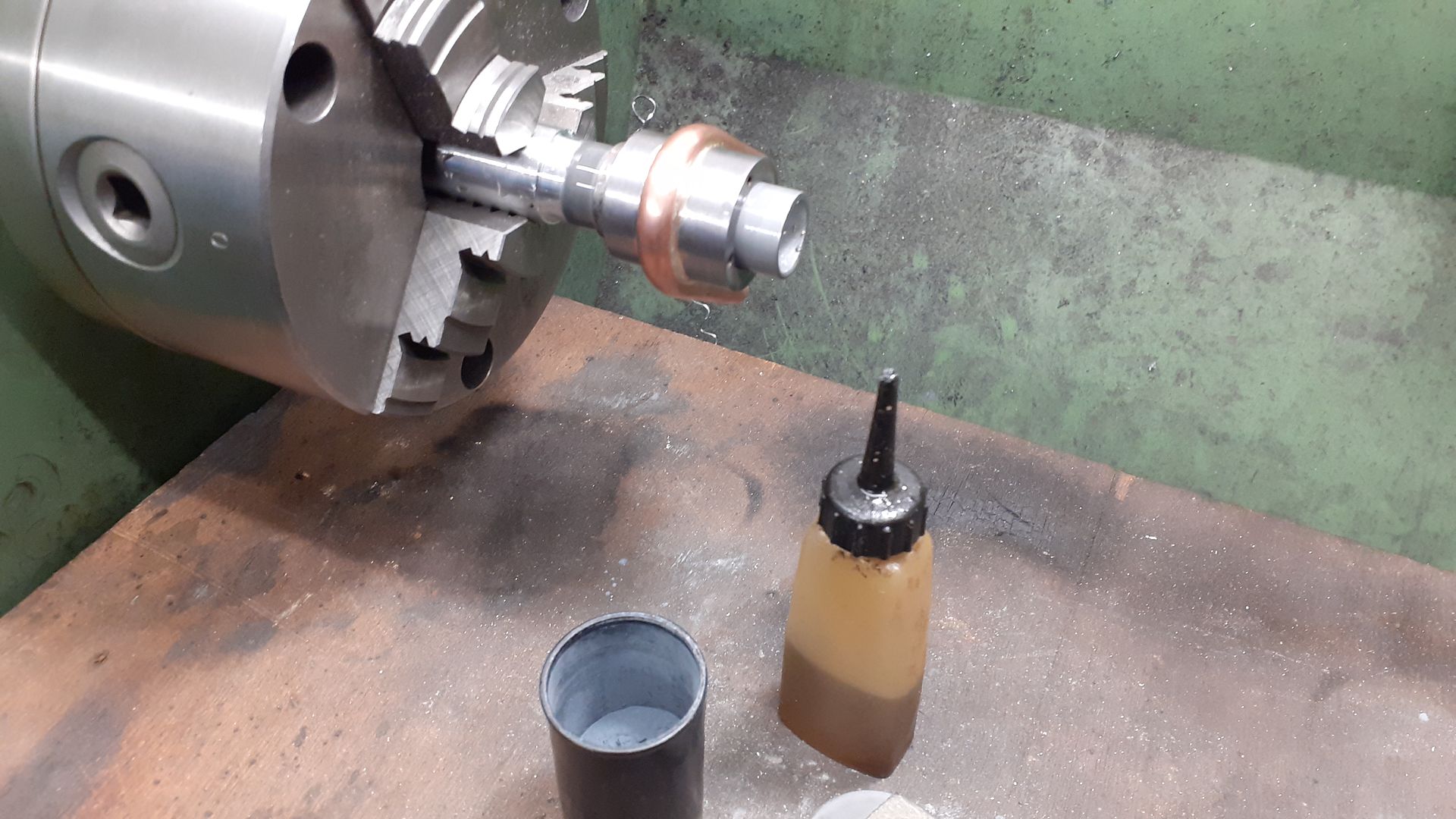
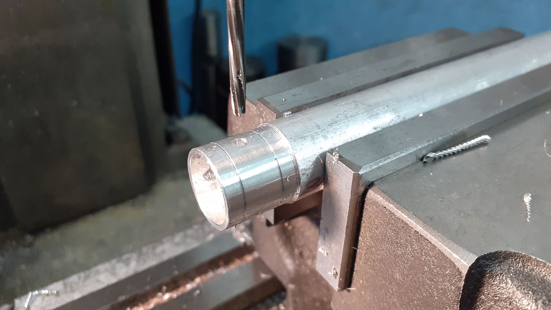
25215 forum posts 3105 photos 1 articles | The piston was fairly straightforward turning and then over to the mill to drill and ream for the 3mm wrist pin before sawing off from the bar and facing the top.
|
| DiogenesII | 09/12/2021 07:40:34 |
| 859 forum posts 268 photos | Nice to see & hear it running, looks like it might be a fun project to make and experiment with.. |
| duncan webster | 11/12/2021 19:28:32 |
| 5307 forum posts 83 photos | The bane of uniflow engines exhausting to atmosphere is compression. The following relies on my reading the drawing in the original mag correctly (it's not that clear), but the distance from the top of the exhaust holes to the cover is 0.534" and the distance from the piston to the cover at TDC is 0.058", so there is a volume compression of 9.2, and as the compression index for air is 1.4, an even higher pressure ratio. As the exhaust holes close, the pressure is 15 psia, it will rise to a high figure at TDC, and when the valve opens the pressure will drop as a slug of air is be pushed out of the cylinder back into the feed pipe. It then takes in air at feed pipe pressure for quite a bit of stroke, but you can see why it needs quite a high line pressure to run. uniflow engines exhausting to atmosphere is compression. Uniflow engines either need a very high inlet pressure (as in flash steam hydroplanes), or a very low exhaust pressure (as in mill engines). The Atkinson Uniflow waggon had auxiliary exhaust valves to overcome this. Husky would probably run on lower pressure if the clearance volume were markedly increased |
| Clive Brown 1 | 22/12/2021 15:23:54 |
| 1050 forum posts 56 photos | A Question primarily for JasonB. I've been looking at the Husky cam design. The valve movement of 1/8" is the same as the port diameter. If the valve is set to fully uncover the port it seems likely to allow air/steam leakage into cylnder when closed. Is there any benefit in slightly increasing the valve travel to provide a better margin for port closure? Another doubt that occurs is that the cam boss is 5/16" id x 7/16" od. Not much meat for the grub-screw to thread into. I'd be very interested in any comments. TIA
|
| JasonB | 22/12/2021 16:43:23 |
25215 forum posts 3105 photos 1 articles | I felt the same so left the valve long then on final assembly put the end of the digi callipers down the valve hole and trimmed the valve so that it came 0.25mm above the top of the inlet hole when in the fully up position
As part of the slimming down of the engine I reduced the crankshaft to 6mm dia and the boss is 10.5mm so I gain a little bit more depth of thread but a 12mm boss would be better though the cam would need enlarging to suit. |
| Clive Brown 1 | 22/12/2021 18:47:10 |
| 1050 forum posts 56 photos | Thanks Jason. I fancy making a Husky as an interesting exercise.Your reply will encourage me to experiment a little bit with the valve arrangement. |
| Neil Wyatt | 24/12/2021 21:34:29 |
 19226 forum posts 749 photos 86 articles | Wonderful engine, (or is it a very elaborate device for blowing raspberries... Neil |
| Ron Laden | 26/12/2021 07:49:04 |
 2320 forum posts 452 photos | Happy Christmas Jason Your re - design certainly improved the look of the engine not so bulky and more open. It runs nicely, certainly can get a lick on, sounds good to. Very nice. Ron |
| Clive Brown 1 | 23/01/2022 09:59:13 |
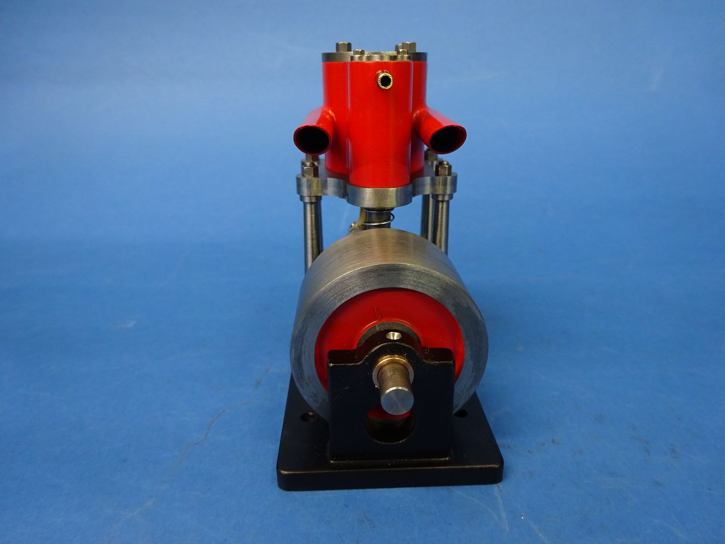
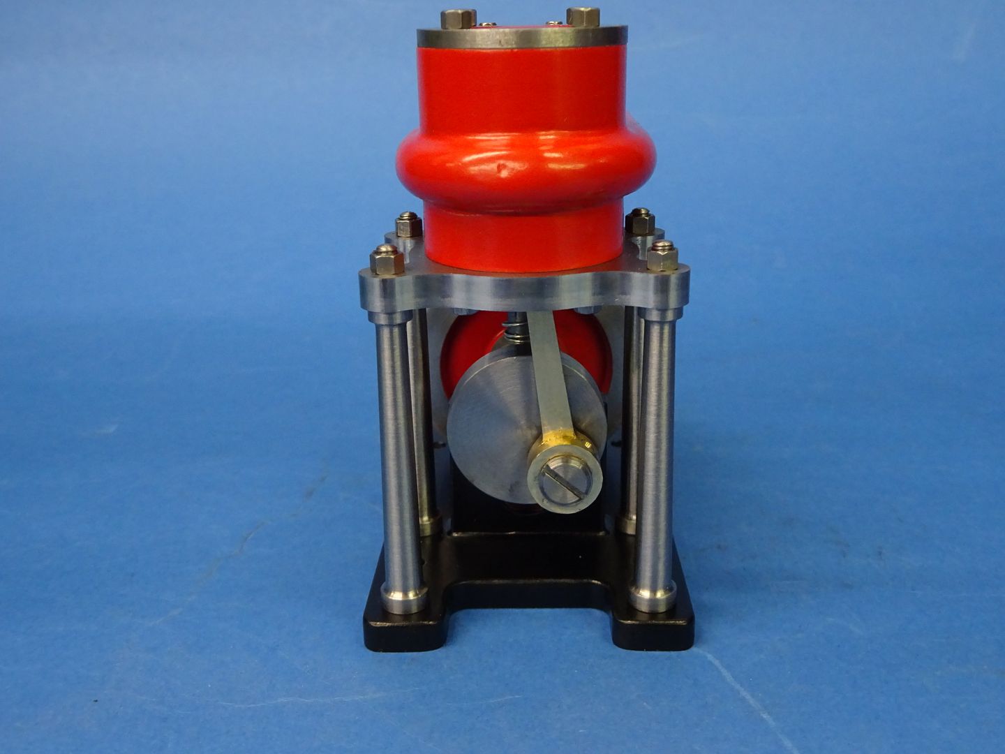
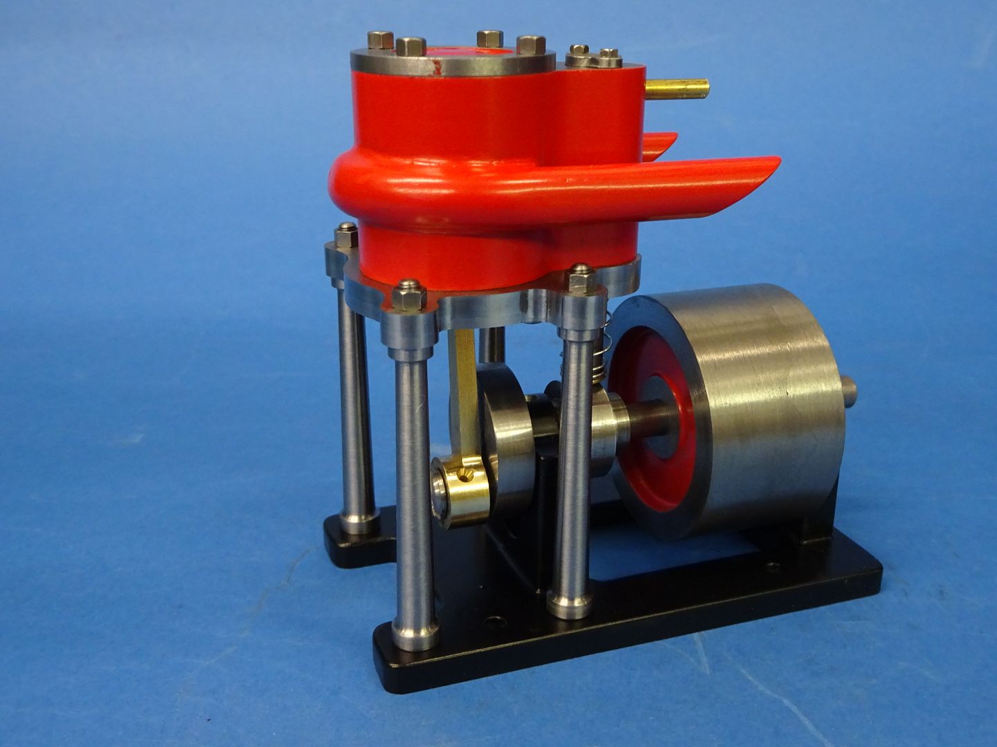
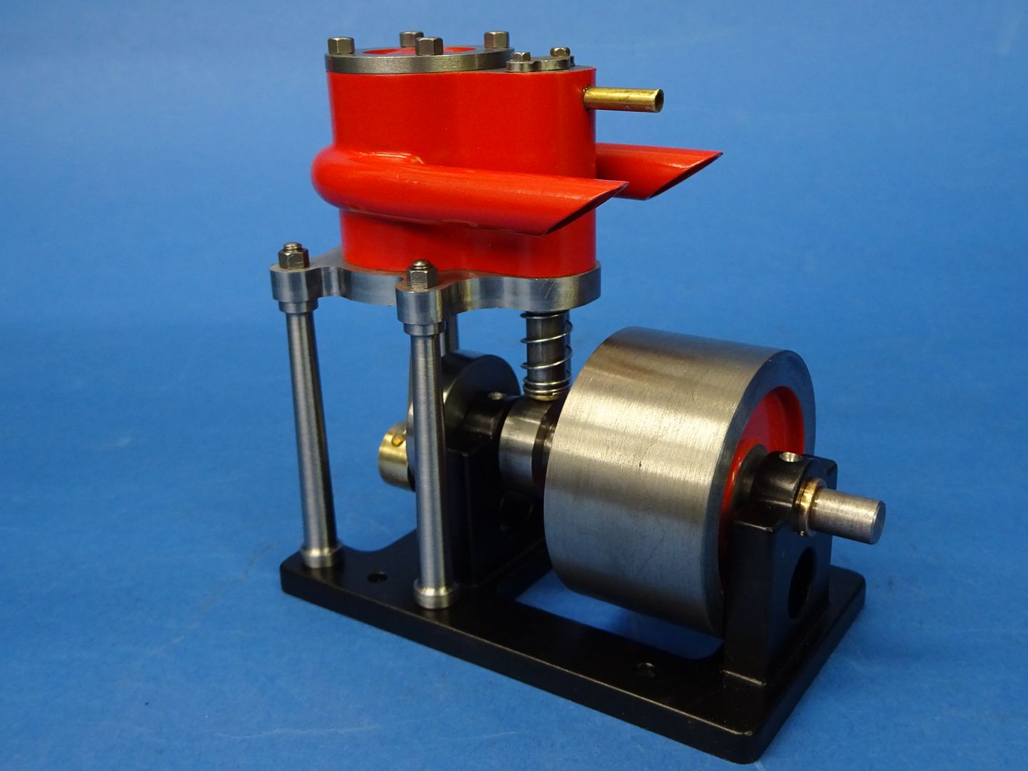
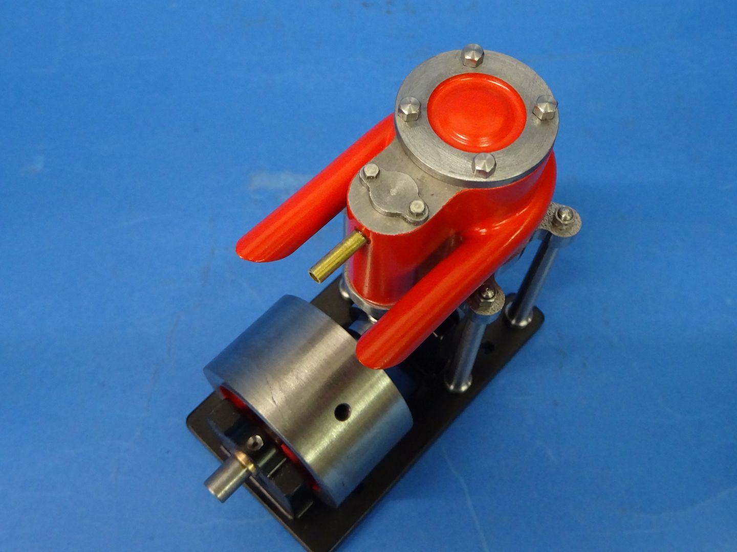
| 1050 forum posts 56 photos | I've not built a uniflow engine up until now so here's my take on Husky, inspired by this thread. Not as elegant as JasonB's but it runs. Basic dimensions are pretty much to the magazine plans. I've slightly increased the cylinder clearance volume at TDC to reduce compression. The valve travel is slightly longer in an attempt to lessen leakage into the cylinder when the inlet port is closed, also the flywheel is heavier. (This post is also a first try at embedding video) https://youtu.be/gZmFcMgk7eY Edit:- was hoping the video would open automatically, however, the link seems selectable and clickable but not ideal.
Edited By Clive Brown 1 on 23/01/2022 10:07:22 Edited By JasonB on 23/01/2022 10:22:23 |
| JasonB | 23/01/2022 10:23:58 |
25215 forum posts 3105 photos 1 articles | Looks to be a good runner and a lot less jumpy than mine unless you have a secret fixing holding it to the bench top |
| Clive Brown 1 | 23/01/2022 10:28:31 |
| 1050 forum posts 56 photos | Thanks for moving the video Jason. It's not fixed but it does start to wander around the bench if I tun the pressure up. |
| duncan webster | 17/02/2022 21:48:01 |
| 5307 forum posts 83 photos | Before jumping in I thought I'd redraw the Popular Science drawings in CAD. Either I'm missing something or the inboard bearing should be moved 3/32 to the left, not as shown in line with the right hand pillars. Anyone else found this? Jason's models/photos seem to be as PopSci, but the cam looks different, lobe not central If this is going to appear as a series in ME I'll has hold off |
| JasonB | 18/02/2022 07:22:58 |
25215 forum posts 3105 photos 1 articles | Just had a quick look at the PS drawings and I make it 1/32" difference , did you allow for the flats on the cyl and valve?
After resizing mine came out to 21mm for both, I also increased the boss on one side of the cam as 3mm would have been a bit small to get a half decent sizes grub screw into. I don't think I will be writing this one up for ME.
|
| Clive Brown 1 | 18/02/2022 09:14:08 |
| 1050 forum posts 56 photos | Duncan, I made mine to the imperial dimensions in the magazine and it fitted together OK. Can't think where the 3/32" could come from. I did at first wonder if you had turned the con-rod so that the big-end boss took up that dimension, but it's 1/8". The cam and valve rod centre lines would be displaced if you moved the inboard bearing. Other changes I made wouldn't affect the bearing position. |
| duncan webster | 18/02/2022 17:14:07 |
| 5307 forum posts 83 photos | Hmmm. If I put the conrod boss in as per left hand view the cam is offset from the valve, if I put the boss out as per Jason model I have to move the bearing, still can't see where I've gone awry. Yes I've allowed for the 1/32 flats
|
| duncan webster | 18/02/2022 17:19:47 |
| 5307 forum posts 83 photos | Sorry about the picture, it's a png from a screenshot converted to jpg using Paint, anyone know how I can make it bigger? |
| duncan webster | 18/02/2022 18:27:28 |
| 5307 forum posts 83 photos | try this |
| JasonB | 18/02/2022 18:37:30 |
25215 forum posts 3105 photos 1 articles | That's better and I can see the problem now. If you look at the light blue line representing the ctr line of the middle column that is not on the same ctr line as the cylinder by what looks like about 1/16" marked in red which is why you are getting 3/32" yet the drawing "error" is only 1/32" Move the cylinder and columns to the same ctr line and also make the crank pin a bit longer so you have some float and it wil run with bearing lined up with end pair of columns
|
| duncan webster | 18/02/2022 19:31:35 |
| 5307 forum posts 83 photos | Gotcha, Thanks |

 )
)


Please login to post a reply.
Magazine Locator
Want the latest issue of Model Engineer or Model Engineers' Workshop? Use our magazine locator links to find your nearest stockist!
Sign up to our Newsletter
Sign up to our newsletter and get a free digital issue.
You can unsubscribe at anytime. View our privacy policy at www.mortons.co.uk/privacy
Latest Forum Posts
- *Oct 2023: FORUM MIGRATION TIMELINE*
05/10/2023 07:57:11 - Making ER11 collet chuck
05/10/2023 07:56:24 - What did you do today? 2023
05/10/2023 07:25:01 - Orrery
05/10/2023 06:00:41 - Wera hand-tools
05/10/2023 05:47:07 - New member
05/10/2023 04:40:11 - Problems with external pot on at1 vfd
05/10/2023 00:06:32 - Drain plug
04/10/2023 23:36:17 - digi phase converter for 10 machines.....
04/10/2023 23:13:48 - Winter Storage Of Locomotives
04/10/2023 21:02:11 - More Latest Posts...
- View All Topics
Support Our Partners


Shopping Partners
Subscription Offer

Latest "For Sale" Ads
- Reeves** - Rebuilt Royal Scot by Martin Evans
by John Broughton
£300.00 - BRITANNIA 5" GAUGE James Perrier
by Jon Seabright 1
£2,500.00 - Drill Grinder - for restoration
by Nigel Graham 2
£0.00 - WARCO WM18 MILLING MACHINE
by Alex Chudley
£1,200.00 - MYFORD SUPER 7 LATHE
by Alex Chudley
£2,000.00 - More "For Sale" Ads...
Latest "Wanted" Ads
- D1-3 backplate
by Michael Horley
Price Not Specified - fixed steady for a Colchester bantam mark1 800
by George Jervis
Price Not Specified - lbsc pansy
by JACK SIDEBOTHAM
Price Not Specified - Pratt Burnerd multifit chuck key.
by Tim Riome
Price Not Specified - BANDSAW BLADE WELDER
by HUGH
Price Not Specified - More "Wanted" Ads...
Get In Touch!
Do you want to contact the Model Engineer and Model Engineers' Workshop team?
You can contact us by phone, mail or email about the magazines including becoming a contributor, submitting reader's letters or making queries about articles. You can also get in touch about this website, advertising or other general issues.
Click THIS LINK for full contact details.
For subscription issues please see THIS LINK.
Digital Back Issues


Donate

 Register
 Log-in
Model Engineer Magazine
- Percival Marshall
- M.E. History
- LittleLEC
- M.E. Clock

ME Workshop
- An Adcock
- & Shipley
- Horizontal
- Mill

Subscribe Now
- Great savings
- Delivered to your door

Pre-order your copy!
- Delivered to your doorstep!
- Free UK delivery!
All Forum Topics > Stationary engines > A Lightweight Husky