Forum sponsored by:

Confused ....Advice needed rotary table vs dividing head
| Bazyle | 15/02/2021 13:36:40 |
 6956 forum posts 229 photos | Bit like the infuriating "Newbie..." and "Please be gentle....". |
| Oily Rag | 15/02/2021 13:58:24 |
 550 forum posts 190 photos | I have some concerns with the statements that have been made above concerning DH's versus RT's. Since when has a DH not allowed the free form production of a radial surface or a slot? (Jason) When a DH will swing through -15degrees up to vertical and beyond (again by a further 15 degrees), this is despite attachments to the mill which allow a inclined table. The handle can be rotated with the plunger in the 'park' position and radial slots and surfaces can be produced. How does a stepper controlled RT deal with step 'dead bands', also the step position is accurate only within the range of the step feedback or encoder resolution, or even the electronics bit conversion function. Analogue is infinitely more accurate than digital (SOD - Computers don't get sums wrong - 'altogether now' - Oh yes they do! Try dividing 10 by 3 and then multiplying the answer by the original divisor - guarantee you won't get 10 as an answer). Also how do steppers deal with backlash? Do they 'dither' in the same way as a Moog valve? Using a RT as a DH for producing such items as splines or gears is problematic in that the cutter is liable to foul the table, unless the component is hanging a long way out from the table, that requires a tailstock to support the overhang. Also how do you produce a bevel gear on an RT that will only align to H or V? - answers on a postcard please. All my RT's are only designed to be used horizontally, they are designed for that purpose. My DH's are all designed as either simple indexers, universal indexers or compound indexers. The later can be driven off the table drive for spiral milling or they can accommodate ANY division requirement by gearing the index plate to the head rotation; thus giving a compounded angularity by movement of the index plate reference point to the handle movement. Sorry to ask these questions but there needs to be 'accuracy of statement' spoken to novices otherwise they will get 'fake news'! And that leads to 'Confusion'! Edited By Oily Rag on 15/02/2021 14:01:45 |
| Nigel McBurney 1 | 15/02/2021 14:15:48 |
 1101 forum posts 3 photos | lots of statements,regarding dividing heads,and some are not entirley true. Comparing a rotary table to a dividing heads is ok but a rotary table with dividing plates or stepping drive can only be compared to a universal dividing head which has a full set of gears which increases the dividing range,carry out helical cutting for gears and threads . Spirals can be cut in a face ,silmilar to the scroll of a 3 jaw chuck,plus cams for auto lathes.I have dividing heads and rotary tables,though the most ffequently used indexing tool is a Marlco twenty four position indexer which is meant to be used with the chuck vertical though it can be used horizontally with an angle plate,24 positions allows indexing of 2,4,6,8,12,24 divisions there is an outer ring divided in degrees.An industrial quality device fitted with a 5 inch Burnerd chuck and an adapter plate to take a 5c collet chuck. Great for making brass fittings with hex features,old style whit nuts and bolts and lots of othe items which require indexing to a good quality but not quite to the precision of a good dividing head,and its quicker to set up and use plus it allows the dividing head to be only used for precise work thus reducing wear and maintaining accuracy. |
| Andrew Johnston | 15/02/2021 14:49:49 |
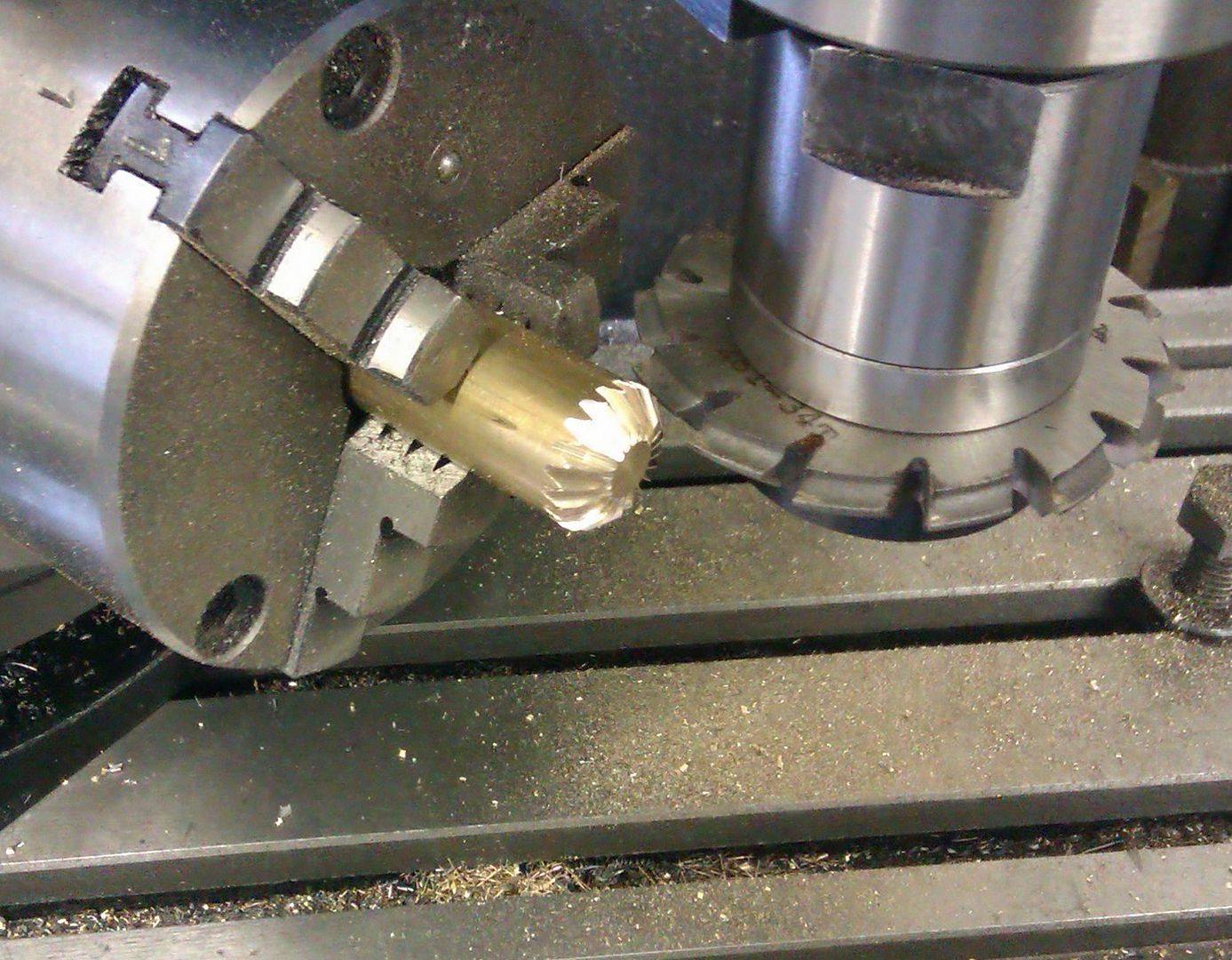
 7061 forum posts 719 photos | Posted by Oily Rag on 15/02/2021 13:58:24: Also how do you produce a bevel gear on an RT that will only align to H or V? Use a CNC mill:
Unlike with a dividing head and involute cutters the above method produces a true bevel gear. Rotary tables and dividing heads are complementary, although there is overlap in use. The well equipped workshop has both. Accuracy, precision and resolution are not the same thing, so one can't say that analogue is more accurate than digital or vice versa. It all depends. It's been some years since I used Moog valves, but I don't recall them having dither? The ones I used were about the size of a small matchbox. We used them as part of a crash gearbox on a racing car. They were current driven, so I designed a voltage driven bi-directional current source to control the valve. Andrew
|
| JasonB | 15/02/2021 15:25:38 |
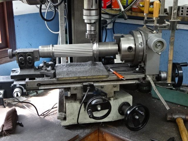
 25215 forum posts 3105 photos 1 articles | Or you mount the R/T at an angle across the table if you want parallel depth method bevel gears. The vast majority of beginners would also have to mount a dividing head in the same way as they are unlikely to have horizontal mills. May also have to do it this way as not all dividing heads tilt.
Edited By JasonB on 15/02/2021 15:43:09 Edited By JasonB on 15/02/2021 16:21:18 |
| Matt Harrington | 15/02/2021 15:33:54 |
 212 forum posts 16 photos | Having had to help a friend recently with the same dilema, I can recommend a Soba HV4 (or HV6) and then you have the option of buying their dividing conversion set (which is not that expensive) Matt |
| Tony Pratt 1 | 15/02/2021 15:38:01 |
| 2319 forum posts 13 photos | It made me smile when SOD mentioned 'division plates are awkward', it's only maths, & making an electronic divider isn't always straightforward.[ I'm half way through one] Tony |
| Me. | 15/02/2021 15:43:23 |
| 147 forum posts 30 photos | Posted by Matt Harrington on 15/02/2021 15:33:54:
Having had to help a friend recently with the same dilema, I can recommend a Soba HV4 (or HV6) and then you have the option of buying their dividing conversion set (which is not that expensive) Matt Thanks - This Newbie always likes the gentle replies.
|
| JasonB | 15/02/2021 15:48:20 |
25215 forum posts 3105 photos 1 articles | Posted by Oily Rag on 15/02/2021 13:58:24:
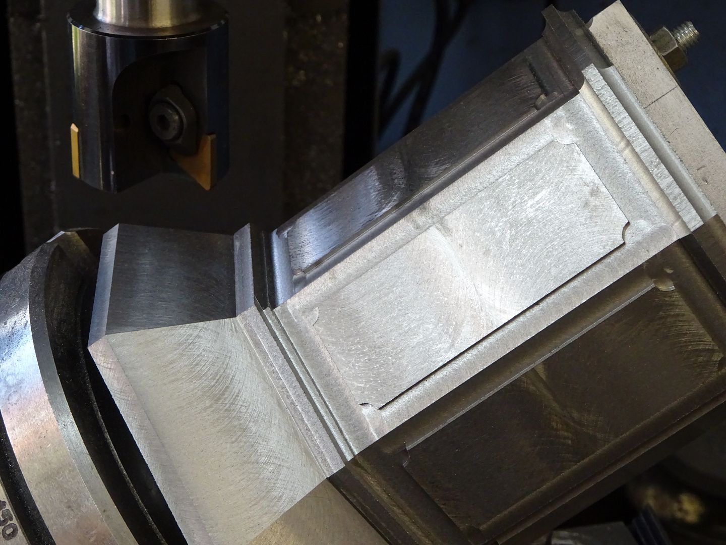
a RT that will only align to H or V? - answers on a postcard please To give beginners the correct info I would have to disagree with that too, here is my R/T set to cut 45deg surfaces
And about a 3deg taper
|
| old mart | 15/02/2021 17:08:00 |
| 4655 forum posts 304 photos | It would be nice to have both, but the op wanted to make the choice between them, not buy both. |
| Andrew Johnston | 15/02/2021 17:30:16 |
7061 forum posts 719 photos | Unfortunately the question has been posed backwards. It would have been better to state what needed to be made and then ask which one would be better. Andrew |
| Oily Rag | 15/02/2021 17:47:16 |
550 forum posts 190 photos | Wow! I have kicked a hornets nest! Andrew: "Accuracy, precision and resolution are not the same thing": Agreed - accuracy is a measure of precision and precision relies upon resolution "It's been some years since I used Moog valves, but I don't recall them having dither? The ones I used were about the size of a small matchbox. We used them as part of a crash gearbox on a racing car. They were current driven, so I designed a voltage driven bi-directional current source to control the valve". As you will be aware the use of a Moog valve requires the definition of the 'null point' - which your bi-directional device would be able to define by measuring the current required to stabilise the valve movement. The Moog operates in a stable way by means of a constant perturbation around the null point, this perturbation is defined in the control system by the 'saw tooth generator' the ramp rate and amplitude of this STG defines, amongst other things the 'dither' and consequently the reaction rate - similarly I used these valves on throttle, variable trumpet drives and gear change systems on Indy, WSC and F1 cars. The null point was typically around 250milliamps but always had to be checked as the bandwidth of valves could be anywhere in the range of, say, 310milliamps to as low as 210milliamps. Get it wrong and the engine speed would creep up or down - trumpets would lengthen or shorten - and gears would mysteriously jump out of mesh! .....one can't say that analogue is more accurate than digital or vice versa Well, I beg to differ here as analogue is a precise value taken from a defined reference, digital is like the old joke about the statistician, the mathematician and the accountant ... Whats 2+2? - Statistician replies 'by all normal indicators it would appear to be somewhere between 3.75 and 4.25; Mathematician replies ' on the basis of a base 10 system it would appear to lie somewhere between 3.5 and 4.5; Accountant replies 'what number did you have in mind?' Remember that digital is a conversion from an analogue value and the absolute value hence appears as a range within the boundaries set by the bit conversion factor. Typically a 5V rail (4.85V with pull down) on a 32bit A2D convertor will have a resolution of 62millivolt. CNC for bevel gears is cheating! I'd show you my set up on a purely manual machine but cannot lay my hands on the photograph at present. Just to point out though that 6 axis machines were available prior to CNC. Jason: ...you mount the R/T at an angle across the table if you want parallel depth method bevel gears. Firstly setting the RT at such an angle directly on the table looks unsafe - given the need to swivel a vertically mounted RT (I note the lack of a tailstock support to your component - not something I would recommend) I would have looked at a swivel platen between the table and the RT. Only direct indexing DH's do not swivel, a true universal and a true compound DH should swivel otherwise they are not, to my mind deserving of being described as either universal or compounded. To give beginners the correct info I would have to disagree with that too, here is my R/T set to cut 45deg surfaces Cannot see the set up so no comment - I presume an angle plate 'twix table and RT And about a 3deg taper The 3 degree tapered flutes, although looking good, it does appear to be tettering on the edge of the acceptable (really - sash clamps!!??) I would not have stretched a machine envelope in such a way as you have shown there. Martin |
| Andrew Johnston | 15/02/2021 21:07:52 |
7061 forum posts 719 photos | Posted by Oily Rag on 15/02/2021 17:47:16:
CNC for bevel gears is cheating! I'd show you my set up on a purely manual machine but cannot lay my hands on the photograph at present. No need to worry about finding the photo. I've made bevel gears the old school way on a manual mill with a dividing head. I wouldn't regard CNC as cheating. If nothing else it taught me a lot about the design of bevel gears, which was needed in order to create the 3D CAD model. For a 32bit ADC reading a 5V signal (assuming that's full scale) I make the LSB 1.1nV? That's the resolution. It will only be precise if the ADC is monotonic and only as accurate as the reference voltage. The Moog valves I used were ±10mA and had no sawtooth as far as I recall, although it was 30+ years ago. The valves were aerospace ones. The gearboxes were used on Indy cars and F1. I worked for Pi Research, who had strong links with the original Ilmor Engineering, and Roger Penske, before Paul Morgan was killed flying a Sea Fury. Who did you work for? Andrew
|
| Oily Rag | 15/02/2021 22:04:43 |
550 forum posts 190 photos | Andrew:- Who did you work for? My racing career started after I originally worked for Lucas Racing. This was after I was seconded from the Petrol Injection Lab at Gt King Street. We did work for all the Indy car teams running the Lucas Mechanical injection systems and then around 1986 introduced the 1K (64 x 16 or 32 x 32 or 48 x 21 [with a lost line!] definable digitally mapped 468 Race ECU's. Involved with Hooker Engines Inc in Indy car (running DFT's) and Granatelli Racing in phoenix. Also worked with Toyota in British F3 supplying the Cellnet sponsored F3 cars (Drivers D.Hill and Martin Donnelly) - this lead to a trip to Japan to calibrate their TOMS F3 cars, which was so successful we were then asked to supply our ECU's to their Turbo V8 Le Mans cars. Meanwhile we also helped with the Paris-Dakar Halt'up Range Rovers which finished second to the works Peugeots 2 years running, and as a time 'filler' worked on the Middlebridge F3000 'Cadbury's sponsored cars' (drivers Phil Andrews and Martin Blundell) this involved some engine development work with Tickford to produce the low friction DFV. Then worked on the TWR Silk Cut Le Mans Jaguars (we did the ignition system - Zytek did the Engine Management). Then worked directly for TWR on their WSC cars and Benetton F1 project (TW was technical director at Benetton). Moved to Zytek to manage their F3000 project using the Judd KV engine, but also did technical support for EDL for the Tyrell Yamaha F1. Then followed the Yamaha engine back to TWR in the Arrows F1 and recruited back to TWR to sort out the gearchange on the Hart engine the following year. Stayed with TWR through to the end (91) then went back to Zytek to set up MZT with Brian Mason. From there on I have been a consultant to various teams and engine manufacturers, both road vehicles and race cars. That's my race CV in a nut shell - Have I got the job? The formative years were completely different though as I served an apprenticeship at Alfred Herberts Ltd,. Coventry. Worked on the first truly CNC machines (Herbert Batchmatic 250 -75) and after the 'Tony Benn DTI 'White Heat of Technology' years realised the M/C tool industry was in terminal decline so moved to the next terminal declining industry - Automotive! I then spent the following years at Standard Triumph working initially on the first digitally mapped injection system (made by Brico - who sold the patents to Lucas) but was involved closely in engine development through developing ECU strategies and algorithms. I met both Paul and Mario on occasions - always had a lot of time for Paul; he was well respected by both Bill Gibson and Brian Mason at Zytek. |
| JasonB | 16/02/2021 07:45:54 |
25215 forum posts 3105 photos 1 articles | Martin Firstly setting the RT at such an angle directly on the table looks unsafe - given the need to swivel a vertically mounted RT (I note the lack of a tailstock support to your component - not something I would recommend) I would have looked at a swivel platen between the table and the RT. Reply I'm not sure what is unsafe, I can use the same two fixings that I would if it were mounted across the table. With such a short stubby workpiece do you really think that a tailstock was needed in that case? Whenever gear cutting is mentioned on this forum the suggestion of Ivan Laws book soon comes up, he shows the same method with his non tilting dividing head mounted at an angle with no tailstock which hundreads of MEs must have followed in the past. . Martin Only direct indexing DH's do not swivel, a true universal and a true compound DH should swivel otherwise they are not, to my mind deserving of being described as either universal or compounded. Reply You did not state what type of Dividing head in your blanket statement . "To give beginners the correct info I would have to disagree with that too, here is my R/T set to cut 45deg surfaces" Martin Cannot see the set up so no comment - I presume an angle plate 'twix table and RT Reply Yes angle plates and additional clamps (clamping set ones not F clamps) . Martin The 3 degree tapered flutes, although looking good, it does appear to be tettering on the edge of the acceptable (really - sash clamps!!??) I would not have stretched a machine envelope in such a way as you have shown there. Reply Yes stretching the machine to it's limit, look closely and you will see the F Clamps are in addition to the usual clamps supplied with the R/T and used to hold the R/T so actually a firmer set up than just the supplied clamps.. |
| Andrew Johnston | 16/02/2021 11:35:55 |
7061 forum posts 719 photos | Martin: Thanks for the exposition. You've certainly had an interesting career. It's a shame that Paul Morgan killed himself in what was a rather unfortunate accident. People in motor racing have a poor record of fatal aircraft crashes. Motor racing can be dangerous, but aviation is particularly unforgiving of over-estimating ones ability. I'm not sure what you mean by a compound dividing head, presumably one that can do compound indexing? While the movements are different I thought compound indexing was mathematically equivalent to differential indexing, which any universal dividing head can do. Andrew |
| Me. | 16/02/2021 12:22:05 |
| 147 forum posts 30 photos | So - if I'm reading this correctly - a plank of wood and a sharp nail will do If I draw a straight line between 3 points and divided the 1st number i thought of by the square route of Pi..... or would a rotary dividing plate table be the answer to my original question....
Thanks for all the input - I'm sure my question got answered. KTF |
| SillyOldDuffer | 16/02/2021 13:59:06 |
| 10668 forum posts 2415 photos | Posted by Me. on 16/02/2021 12:22:05:
So - if I'm reading this correctly - a plank of wood and a sharp nail will do If I draw a straight line between 3 points and divided the 1st number i thought of by the square route of Pi..... or would a rotary dividing plate table be the answer to my original question....
Thanks for all the input - I'm sure my question got answered. KTF It did! In the absence of a specific reason for needing a Dividing Head, you probably want a Rotary Table plus Index Plate accessories. But on the way, your question raised some interesting issues and I can't help picking up on Tony Pratt's comment "it's just maths", and Martin (Oily Rag's ) remarks about analogue vs digital and computer accuracy! Not everyone is good at maths, which I think can be demonstrated by this relevant question: Assuming a Rotary Table has a 40:1 worm and an indexing plate with hole circles from 30 to 60, each circle in steps of one, thus:
Q1. Using this plate, what indexing ratio is needed to rotate the rotary table by 5.29°? (There are two candidates.) Q2. What's the error, in degrees, of both indexing ratios? Show working! If you happen to have a lookup table for a 40:1 ratio, please don't cheat by using it. The test is doing the maths. ----------------------------- My HV6-style rotary table has a 90:1 worm, so each turn of the handle moves the table 4°. How accurately I can set it manually depends on the scale, how well I read the crude vernier, how consistent the worm and gear are end-to-end, plus a multitude of other small mechanical quirks. Most stepper motors have a basic 200 steps per rotation, which is 0.02° per step when applied directly to a 4° handle. But that's not how it's done because stepper motors can be micro-stepped . A motor applying 1600 micro-steps to a 4° per turn handle is turning in increments of 0.0025°, or 0° 0' 9". Are the holes in an analogue Index plate spaced that accurately, and does the pin engage all of them without wobble? Probably not. It's not the number system or digital stepping that limits accuracy, it's the hardware. Martin also criticises computers because decimal arithmetic isn't always spot on, quoting 10/3 * 3 = 9.999 recurring compared with 3⅓ x 3 equals exactly 3. Fair enough except fractions are equally bad! The square root of 2, e, pi and an infinity of other numbers can't be represented accurately by fractions. So decimal numbers fail the Oily Rag test, and rational fractions fail mine. It's a score draw! Both systems require the user to understand error. One of several advantages decimal numbers have is the error level can be reduced to a suitably convenient value simply by calculating more digits. And although both systems are erroneous it's less clumsy to calculate with pi = 3.1415926539214210447087 than pi = 104348/33215, especially when a calculator or computer does the work. Finally, surely unfair for Martin to criticise computers for tiny binary rounding errors in comparison with the arithmetic performance of the average human. People make lots of silly mistakes due to boredom, distractions, and faulty memory. Some of us much worse than others...
Dave
|
| Oily Rag | 16/02/2021 14:29:22 |
550 forum posts 190 photos | Andrew, I think we have hi-jacked Me.s thread enough! Just to define what I term as a compound (and I accept your differential indexing as a complimentary description) DH I would offer as an example the Walther UTE 100 model which has the ability to drive the index plate mechanism direct from the main DH mandrel and hence the index plate will move either contra or in unison with movements input by the operator. This head can also be driven by the gear train attached to the table feed mechanism to provide spiral milling. A 'Universal' head on the other hand may only be useable for spiral milling without the 'differential' drive to the index plate. My example of this DH would be the Hoffman style head and the Aciera type 100 head, although the Aciera head has no 'swivelling' capability; as on the Aciera machine this is covered by the 4 axis compound quartering table onto which the DH will mount. As shown below:-
Finally I come to the 'simple' indexer. Again I would here use as an example the Aciera Simple DH which has interchangeable division plates of 12, 17, 18, 19, 21, 48 and 60. These plates helpfully also fit the Aciera Universal head as complimentary units.
|
| Me. | 16/02/2021 14:32:41 |
| 147 forum posts 30 photos | Its the answer "42"
Edited By Me. on 16/02/2021 14:34:02 |


Please login to post a reply.
Magazine Locator
Want the latest issue of Model Engineer or Model Engineers' Workshop? Use our magazine locator links to find your nearest stockist!
Sign up to our Newsletter
Sign up to our newsletter and get a free digital issue.
You can unsubscribe at anytime. View our privacy policy at www.mortons.co.uk/privacy
Latest Forum Posts
- *Oct 2023: FORUM MIGRATION TIMELINE*
05/10/2023 07:57:11 - Making ER11 collet chuck
05/10/2023 07:56:24 - What did you do today? 2023
05/10/2023 07:25:01 - Orrery
05/10/2023 06:00:41 - Wera hand-tools
05/10/2023 05:47:07 - New member
05/10/2023 04:40:11 - Problems with external pot on at1 vfd
05/10/2023 00:06:32 - Drain plug
04/10/2023 23:36:17 - digi phase converter for 10 machines.....
04/10/2023 23:13:48 - Winter Storage Of Locomotives
04/10/2023 21:02:11 - More Latest Posts...
- View All Topics
Support Our Partners


Shopping Partners
Subscription Offer

Latest "For Sale" Ads
- Reeves** - Rebuilt Royal Scot by Martin Evans
by John Broughton
£300.00 - BRITANNIA 5" GAUGE James Perrier
by Jon Seabright 1
£2,500.00 - Drill Grinder - for restoration
by Nigel Graham 2
£0.00 - WARCO WM18 MILLING MACHINE
by Alex Chudley
£1,200.00 - MYFORD SUPER 7 LATHE
by Alex Chudley
£2,000.00 - More "For Sale" Ads...
Latest "Wanted" Ads
- D1-3 backplate
by Michael Horley
Price Not Specified - fixed steady for a Colchester bantam mark1 800
by George Jervis
Price Not Specified - lbsc pansy
by JACK SIDEBOTHAM
Price Not Specified - Pratt Burnerd multifit chuck key.
by Tim Riome
Price Not Specified - BANDSAW BLADE WELDER
by HUGH
Price Not Specified - More "Wanted" Ads...
Get In Touch!
Do you want to contact the Model Engineer and Model Engineers' Workshop team?
You can contact us by phone, mail or email about the magazines including becoming a contributor, submitting reader's letters or making queries about articles. You can also get in touch about this website, advertising or other general issues.
Click THIS LINK for full contact details.
For subscription issues please see THIS LINK.
Digital Back Issues


Donate

 Register
 Log-in
Model Engineer Magazine
- Percival Marshall
- M.E. History
- LittleLEC
- M.E. Clock

ME Workshop
- An Adcock
- & Shipley
- Horizontal
- Mill

Subscribe Now
- Great savings
- Delivered to your door

Pre-order your copy!
- Delivered to your doorstep!
- Free UK delivery!
All Forum Topics > Beginners questions > Confused ....Advice needed rotary table vs dividing head