Forum sponsored by:

Resurrecting a Stuart 10V
| Former Member | 03/02/2021 17:36:55 |
| 1085 forum posts | [This posting has been removed] |
| Colin Heseltine | 03/02/2021 18:09:52 |
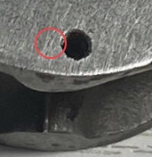
| 744 forum posts 375 photos | Having had a much closer look and spotting some "white stuff" in the miss-shaped port it looks as though there is a small blow-hole between the exhaust port and the miss-shaped inlet port or more likely when drilling the port through from the end of the cylinder it was drilled too far. It has possible had some filler put in somehow. Looks like it will definitely have to be the brass insert. I think the insert will have to be at least 1/4" thick as it is now going to have to replace the port slots in their entirety.
Colin
|
| Dr_GMJN | 03/02/2021 18:40:09 |
 1602 forum posts | Posted by JasonB on 03/02/2021 17:13:30:
One option would be to mill out a recess say 1/16" thick to just beyond the area that the steam chest covers and JBWeld in a plate that could be cut from brass. Mill the ports in it first rather than risk having to remove it if something goes wrong while machining in place.
Different wear rates when the slider moves over that area? Could also stick a drill shank down the port holes before it set to avoid re-drilling them?
|
| JasonB | 03/02/2021 19:06:31 |
 25215 forum posts 3105 photos 1 articles | JBW would probably work OK too, just give the surfaces a once over with a small burr in the dremel to key them and also remove any traces of old oil. Then machine the ports again once set. I doubt the JBW would wear down as most of the valve will be sitting on the surrounding cast iron |
| Dr_GMJN | 03/02/2021 22:07:58 |
1602 forum posts | The port face itself looks very rough. I know it’s a close-up image, but even so... Looks like it could do with a bit of a skim - which would also level any remedial work on the ports. |
| Colin Heseltine | 04/02/2021 17:32:49 |
| 744 forum posts 375 photos | Well I opted to mill out the poorly formed ports. In order to do this I needed to remove the studs the previous builder had fitted for the top and bottom covers in order to mount in the vice. The studs decided to fight back. Well one of them did. Five on the upper cover end came out easily. Four of the lower ones came out relatively easily. The last one fought back and said no way am I leaving this casting in one piece and promptly sheared flush wit the top of lower face. Bugger I thought. I knew drilling it out would be fraught as it needed a 2mm tapping drill size and if this wandered being such a thin drill it would go down the casting in preference to the stud. I set it up in the vice and refitted and bolted the top cover down.
This now gave me a fixed location. I then used my centering scope for the first time in anger to locate on the hole in the cover.
Once located i remove the top cover and the studs. Fitted a 2mm slot mill and very gingerly raised the table to bring cutter and stud together. Ran at approx 1500rpm and worked my way through the stud. Once remnants cleared out was able to run 7BA tap back down the hole. That was quite a relief. Blued up the port face on the cylinder and lightly scribed a box around the area to be milled out. This was my sanity check to ensure I had my DRO settings correct. Clamped in vice and set level and set up a 3/16 slot mill.
Initially put in four corner holes at 1/8" depth, then reduced the DOC to 1/16" and milled out first layer. Dropped down to the 1/8" point and took out another layer. I was hoping to get away with this but needed another 1/16". Looked good at this point so them went round the periphery with a full depth cut removing final/1/64" all round.
Pleased with that now need to make the brass insert. I have never used JBWeld before so am not sure how much smaller I need to make the brass insert. I assume I need the JBWeld as thin as possible. Is it fairly thin as soon as it is mixed. I was think that when the brass insert is pushed into place to use, either flypress or arbor press to push it as fully home as possible. Colin
|
| JasonB | 04/02/2021 18:23:44 |
25215 forum posts 3105 photos 1 articles | It's more liquid than most car body fillers but a bit thicker than epoxy such as Araldite. Spread a thin amount on all surfaces and push it in, just squeezing in the vice would do. Couple of thou clearance would be more than enough. No need to rush things a sit has a long pen time. |
| Dr_GMJN | 04/02/2021 19:49:23 |
1602 forum posts | I'm intrigued to see the port relief pockets in each end of the cylinder... I can't see how the drillings can be so far out of alignment and still be in the right place in the cylinder pockets. From the filed soleplate, it seems like the original builder might not have had the benefit of a milling machine? |
| JasonB | 04/02/2021 19:54:45 |
25215 forum posts 3105 photos 1 articles | Quite possible. Funny enough I was looking at the book on the Stuart Progress engines yesterday and the cavity in the valve is shown being cut with a small coal chisel. |
| Colin Heseltine | 04/02/2021 20:28:55 |
| 744 forum posts 375 photos | Jason, Thanks for that. I will try and get that bit made tomorrow.
Dr_GMJN, Your wish is my command.
You will also spot that the 5 holes are not quite centered where they should be. It is what it is. Hopefully it will run a lots better and look a lot better when finished. Colin |
| Former Member | 04/02/2021 20:37:55 |
| 1085 forum posts | [This posting has been removed] |
| Colin Heseltine | 04/02/2021 21:00:01 |
| 744 forum posts 375 photos | Br, I had to use the better positioned holes for the mount to the standard otherwise the valve chest is even more out of alignment with the eccentric. I don't want to end up remaking everything. Hopefully it wont look too bad by the time it has a coat of paint on it along with reversing gear.. Colin |
| Dr_GMJN | 04/02/2021 21:14:38 |
1602 forum posts | I've not used JB Weld yet, but from what I've heard I wonder if it would be possible to fill the top cover holes and re-drill/tap? Even without that, it doesn't look they're far off being suitable for re-drilling and almost missing the originals. Depends on what you want at the end, but to me, that top PCD is one of the key things to get looking right, along with the alignment of the valve chest cover fixings. |
| Former Member | 04/02/2021 21:21:03 |
| 1085 forum posts | [This posting has been removed] |
| Neil A | 04/02/2021 22:21:15 |
| 160 forum posts | Funny you should mention the number of holes in the covers. My 10V of mid 70's vintage has 4 holes in the bottom face of the cylinder to the standard and 6 holes in the top face for the cover. I've just checked the drawing to make sure. The design seems to have changed a bit over the years. Neil |
| Colin Heseltine | 04/02/2021 23:31:49 |
| 744 forum posts 375 photos | Dr_GMJN I have just looked at that option. I would need to drill every single hole in the top face near enough 50% in cast iron and 50% in JBWeld. Not sure quite how well that would work out. I do not know whether the drill would wander between the two materials. I guess the other option would be do do like I did with the broken stud and use a 2mm slot drill rather than a 2mm ordinary drill. Maybe a 5/64" slot mill would be even better as it is only 6/10's of thou under 2mm. It also assumes I can fill the holes completely with JBWeld. Maybe instead of JBWeld it might be easier to loctite in short sections of 7BA stud and then use slot mill to produce the hole as with the JBWeld option. Br. The idea of six holes is a good one, but having drilled and tapped holes for drain cocks, these would be in the way of the holes in the 90 and 270 degree positions. I will sleep on it. Colin |
| Dr_GMJN | 05/02/2021 00:18:37 |
1602 forum posts | I can’t comment on slot drills because I only seem to use them to mess things up. If you were to drill pilot holes of smaller diameter, could you get those 100% in cast iron? If so, would the tapping drill then follow the pilot hole and make wandering less likely? I would have thought that drilling into a perfect interface between a Solidified liquid and tapped hole wouldn’t pose much of an issue, especially since it looks like significantly more than 180 degrees would be in solid metal? I suppose you could drill the existing holes massively oversize and bond in some brass bar, then drill that - a bit like the valve face? |
| JasonB | 05/02/2021 07:05:12 |
25215 forum posts 3105 photos 1 articles | If it were me wanting to shift those holes I would take say a 4mm 3-flute cutter and plunge in at the correct positions which would hopefully have all the existing hole within the new one. Then either turn and thread some bushes and JBWeld them in place or JBWeld in some turned CI plugs which could then be drilled & tapped in position. A drill will wander if you are 50/50 into CI and JBweld and even if you do the cut with a milling cutter the tap will still wander off into the JBWeld. |
| Dr_GMJN | 05/02/2021 08:09:00 |
1602 forum posts | Obviously there’s some parallax in the image, but I’d have thought there would be just enough of a complete new circle to avoid any wandering, especially if the tap drill hole was piloted with a central unbroken hole?
Then again, perhaps the new drill would get dragged over by the lower right edge of the existing hole during drilling? |
| Former Member | 05/02/2021 09:02:58 |
| 1085 forum posts | [This posting has been removed] |


Please login to post a reply.
Magazine Locator
Want the latest issue of Model Engineer or Model Engineers' Workshop? Use our magazine locator links to find your nearest stockist!
Sign up to our Newsletter
Sign up to our newsletter and get a free digital issue.
You can unsubscribe at anytime. View our privacy policy at www.mortons.co.uk/privacy
Latest Forum Posts
- *Oct 2023: FORUM MIGRATION TIMELINE*
05/10/2023 07:57:11 - Making ER11 collet chuck
05/10/2023 07:56:24 - What did you do today? 2023
05/10/2023 07:25:01 - Orrery
05/10/2023 06:00:41 - Wera hand-tools
05/10/2023 05:47:07 - New member
05/10/2023 04:40:11 - Problems with external pot on at1 vfd
05/10/2023 00:06:32 - Drain plug
04/10/2023 23:36:17 - digi phase converter for 10 machines.....
04/10/2023 23:13:48 - Winter Storage Of Locomotives
04/10/2023 21:02:11 - More Latest Posts...
- View All Topics
Support Our Partners


Shopping Partners
Subscription Offer

Latest "For Sale" Ads
- Reeves** - Rebuilt Royal Scot by Martin Evans
by John Broughton
£300.00 - BRITANNIA 5" GAUGE James Perrier
by Jon Seabright 1
£2,500.00 - Drill Grinder - for restoration
by Nigel Graham 2
£0.00 - WARCO WM18 MILLING MACHINE
by Alex Chudley
£1,200.00 - MYFORD SUPER 7 LATHE
by Alex Chudley
£2,000.00 - More "For Sale" Ads...
Latest "Wanted" Ads
- D1-3 backplate
by Michael Horley
Price Not Specified - fixed steady for a Colchester bantam mark1 800
by George Jervis
Price Not Specified - lbsc pansy
by JACK SIDEBOTHAM
Price Not Specified - Pratt Burnerd multifit chuck key.
by Tim Riome
Price Not Specified - BANDSAW BLADE WELDER
by HUGH
Price Not Specified - More "Wanted" Ads...
Get In Touch!
Do you want to contact the Model Engineer and Model Engineers' Workshop team?
You can contact us by phone, mail or email about the magazines including becoming a contributor, submitting reader's letters or making queries about articles. You can also get in touch about this website, advertising or other general issues.
Click THIS LINK for full contact details.
For subscription issues please see THIS LINK.
Digital Back Issues


Donate

 Register
 Log-in
Model Engineer Magazine
- Percival Marshall
- M.E. History
- LittleLEC
- M.E. Clock

ME Workshop
- An Adcock
- & Shipley
- Horizontal
- Mill

Subscribe Now
- Great savings
- Delivered to your door

Pre-order your copy!
- Delivered to your doorstep!
- Free UK delivery!
All Forum Topics > Work In Progress and completed items > Resurrecting a Stuart 10V