Forum sponsored by:

VFD. XSY AT4 220v 1phase to 380v 3phase advice sort
| Andrew Firman | 24/05/2020 14:49:47 |
| 37 forum posts 18 photos | Many thanks Martin, The PE terminal is quite easy to see when the board is removed from the case. There is a red wire that connects the terminal and the main board and then through the brass board supports to the fins
The pot is new with a measured resistance of 10.7K . It seems ok but I don’t have any others to swap it with - awaiting a couple from China. I have set P10 and P11 to 2. I’ve checked the voltage between fins and a mains supply earth connected to the PE terminal and now get a reading of 3v ac down from 85v. Don’t know why it’s not zero but I guess one can live with 3v
|
| Andrew Firman | 24/05/2020 15:02:24 |
| 37 forum posts 18 photos | The pot I’m using.
|
| Andrew Firman | 24/05/2020 22:23:49 |
| 37 forum posts 18 photos | Posted by James Walker on 23/05/2020 21:58:39:
Gents I have 2 of these VFDs commissioned on a Dah Lih mill. They run the Vertical, Horizontal and Power Feed motors. All motors are 380/400V 3ph. They are wired up to expect that range. As noted this model VFD converts 220-240V 1PH in and spits out 380V/3PH. The control pot I use is 10K. It is wired per the manuals instructions. I used Parameters P73 and P74 as noted by Bruce to adjust to get the response I wanted from the 10K pot. I am happy to check and post the parameters I have set for all the key values if that is of interest and would be helpful. I know when I did my install the level of info on this control as a bit like getting blood from a stone. So after lots of experimenting I solved most things and have it operating. Cheers, James.
Sorry James, I somehow missed your post. I would be very grateful if you would post your parameter settings. As you say blood from a stone.... and to add insult to injury one of the 2 AT4s I have no longer powers my test motor smoothly, so another issue to sort...,.
|
| SillyOldDuffer | 25/05/2020 10:00:39 |
| 10668 forum posts 2415 photos | Don't get hung up on the value of the potentiometer! It's used to divide a voltage, and, provided it doesn't draw too much current, almost any value will do. The AT series 5V/10V output is specified to deliver up to 20mA. When a 10kΩ pot is used it draws 1mA. A 4.7kΩ pot draws 2.1mA The difference is trivial. There are limits: the speed control input needs a certain amount of current to work, and a high-value pot might not provide enough. And a very low-value pot will draw too much current, possibly damaging itself or the power supply. For this application I'd guess any pot between 1kΩ and 100kΩ will work, with 3.3 to 10kΩ being typical. Dave |
| Martin of Wick | 25/05/2020 10:59:27 |
| 258 forum posts 11 photos | Andrew, lashed up an arrangement with the AT4. Voltage across the VR (5V to Com) was 5.1 volts Potential on earth (PE to 220v mains incomer) 0.02V max couldn't find my 10k pot but with 4.7k I get about 0 to 29 Hz across the range which is about right as I set the max frequency at 65Hz in the table. James, it is always useful to see what parameters others are using in their set ups.
Edited By Martin of Wick on 25/05/2020 11:20:36 |
| Andrew Firman | 25/05/2020 11:34:17 |
| 37 forum posts 18 photos | That’s interesting Dave because I get half max hz using a 10K pot. |
| Martin of Wick | 25/05/2020 11:46:16 |
| 258 forum posts 11 photos | Further tests.... I am beginning to doubt my own sanity...Some apologies due. Something Dave said made me think.. Managed to find a 25k pot to replace the 4.7 and set up Result Max Hz 31 !!! How could that be? I was expecting 0 to 65 Hz but controlled only over half span. So looked at P73 setting and reduced it to manual setting of 31000 as a trial - low and behold the full range of 0 to 64 Hz restored. So apologies for misinformation - Bad to rely on my memory, but I would have sworn when I tested months ago I had to have P73 at 61000 for full speed and left the parameter in that state for later installation, obviously I was not paying attention at the time. Suffice to say, have a go with the info sheet values input in P73 and 74 and see what happens. Rough running of motor - is that at low speed? sometimes too high a value in P72 torque compensation will cause 'cogging' of the motor.
Edited By Martin of Wick on 25/05/2020 11:49:19 |
| Martin of Wick | 25/05/2020 12:08:35 |
| 258 forum posts 11 photos | And just for further information, If you set P73 at 31000, I think you may get the external pot to control between 0 to 65Hz (if you have set 65 in P06) BUT when you switch back to panel control you will find that you can control the frequency OK (0 to 65) but only over half the span of the panel pot! To restore full span control on the panel pot, you have to bring P73 back to 61000 and probably the source of my confusion - panel and external don't set up the same way on this device and the manufacturers supply on the assumption that the panel pot will be the primary control, but don't bother informing you of the parameter changes needed for external control.
|
| Andrew Firman | 25/05/2020 12:44:51 |
| 37 forum posts 18 photos | Well done Martin (and Dave) 😊. 10K pot working properly and as you say changing back to panel pot results in full hz being achieved at 50% of setting with no further increase if one continues to 100%.
Thanks for your time in resolving this conundrum. |
| James Walker | 25/05/2020 22:32:27 |
| 11 forum posts 1 photos | In case it is useful here are the values I am running on the key settings. Note - I did a factory reset of values so I will note only things that are different to the defaults per the VERY small manual. I also adjusted for a higher voltage curve to get the response I wanted out of my motors.
P01=60 P02=45 P03=2.5 P04=20 P06=60 P07=15 (this is per recommendations I have found as these style VFDs do perform poorloy under 15Hz) P10=2 P11=2 P20=60 P21=1420 P22=6 (this setting impacts the sinnging sound of the motor. The higher the setting the quieter it is as it goes out of juman hearing. However higher frequency is harder on insulation. So on old motors lower is safer, balanced with noise/annoyance factor) I have factory defaults on P65 and on. This includes the settings for the external pot. But to explicit here are those values. P73=31440 P74=2096 P75=1130 P76=9500
|
| James Walker | 25/05/2020 22:42:38 |
| 11 forum posts 1 photos | This is also a useful bit of info. These graphs show different torque curves based on how you set the mix of min/intermediate/max voltage and frequency. Max frequency on the graph is reference off P01 wit the others being P02 to P07.
|
| Andrew Firman | 26/05/2020 00:31:59 |
| 37 forum posts 18 photos | Thanks James, very helpful.
|
| Steviegtr | 26/05/2020 01:25:04 |
 2668 forum posts 352 photos | Not had anything to do with your model, but on my Toshiba I was having motor troubles like you mention. It turned out to be the setting for the base frequency of the motor. Which is 50hz in this country, it was set to 60hz. Changed it to 50 & all was well again. Steve. |
| James Walker | 26/05/2020 02:10:24 |
| 11 forum posts 1 photos | Posted by Steviegtr on 26/05/2020 01:25:04:
Not had anything to do with your model, but on my Toshiba I was having motor troubles like you mention. It turned out to be the setting for the base frequency of the motor. Which is 50hz in this country, it was set to 60hz. Changed it to 50 & all was well again. Steve. This is a good point. I used 60Hz as my motors talk to a 50 and 60Hz rating (P01). This meant I could get full speed out of the motors and increase versatility. You can set max Hz (P06) higher than P01). However I believe the curve flat-lines after you exceed the reference set in P01. So while the frequency and thus speed of the motor will increase you do not also get the voltage increasing. It is all a balancing act.
|
| Andrew Firman | 26/05/2020 14:21:51 |
| 37 forum posts 18 photos | James, I tried using your P00 to P07 parameters but was unable to lower P03 below 4.0 so left all at the manual default settings. I changed P73 to P76 the manual defaults. Everything seems to work as it should except for the vibration when using Vfd#1. I'm wondering whether we have the same versions of the AT4. Mine is version A03. I purchased mine in March 2019 and am only now getting round to checking them!
As mentioned before one of my AT4s (both setup with identical parameters) seems to cause a pronounced lowish frequency vibration. I've tried to illustrate in the linked videos
Video motor noise using different AT4s
at 50hz #1Vdf ( noisy one) has a panel indicated current of 2.122 amps and clamp meter measured 1.32, 1.43 and 1.11 amps for W, V and U #2Vdf has a panel indicated current of 1.985 amps and clamp meter measured 1.44, 1.51 and 1.50 amps for W, V and U All measured currents are above the motor plate 1.26 amps rating. Should I be concerned about this? Would the significantly unbalanced outputs currents on #1Vfd be the cause of the vibration? I guess there is no way of balancing the output currents? |
| Martin of Wick | 26/05/2020 18:23:30 |
| 258 forum posts 11 photos | If it is of any comfort, my devices all bear that label, but I wouldn't set any great significance to that. I doubt the QA extends to identifying the numerous production variants. Once the box has left the factory, you are on your own and up the creek.... Just sayin! Until you really know if you need to modify the torque curve, best keep it linear as per the defaults. Shovelling more amps and volts into the motor at its most vulnerable (reduced RPM) is a good way to shorten its life. wouldn't worry to much about the indicated currents as long as the motor isn't overheating. I doubt this device samples or filters the values so you are seeing the peaks. Strange that one of the phases is 20% out. If true, and happens on all motors, that is quite significant and could be a cause of rough running. Not encountered this problem before. You could see if making small changes to the carrier frequency P22 on VFD1 makes any difference ( no more than + or - 5 from the default value of 10 in either direction). Beware that increasing the frequency significantly will increase the running temperature of the motor (but make it quieter as somebody has pointed out). And vice versa. Sometimes you just have to fiddle and even that doesn't always do the trick! Edited By Martin of Wick on 26/05/2020 18:26:11 |
| Andrew Firman | 26/05/2020 19:29:07 |
| 37 forum posts 18 photos | I suppose a better way of determining the version would be to compare dates printed on the pcbs. Reducing P22 from 10 to 6 but it didn’t seem to make an apparent difference to the vibration. I guess the next step for me is to complete the enclosures, control panels, wiring and fit to my new to me T S M1 and start making chips 😊 Thanks everyone who has contributed knowledge and advice. |
| OneManEngineering | 02/08/2020 12:49:17 |
| 33 forum posts 48 photos | Posted by Andrew Firman on 23/05/2020 13:32:14:
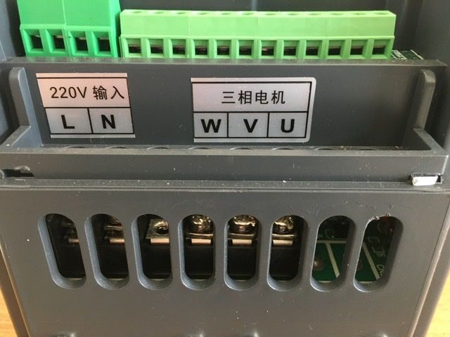
I have a couple of 2.2Kw XSY AT4 which I want to use to power a couple of 380V 3 phase star wired motors using 220v single phase supply.
Greg Edited By Greg The Londoner on 02/08/2020 12:49:41 |
| OneManEngineering | 02/08/2020 19:39:15 |
| 33 forum posts 48 photos | Also Can someone shed some light as to why I can not go over 220V in P000, where I should be able to reach 380V. Ive got XSY-AT4 as well. Is it a faulty item, or supposed to be this way?
https://youtu.be/4tr-i-XGOC8
Thanks, Greg Edited By OneManEngineering on 02/08/2020 19:47:09 |
| Andrew Firman | 02/08/2020 20:12:59 |
| 37 forum posts 18 photos | Greg, Although the "manual" does not explain I believe P000 is the input voltage which should be left at 220V. That's what mine are set at and both 380 star configured motors run fine.
|


Please login to post a reply.
Magazine Locator
Want the latest issue of Model Engineer or Model Engineers' Workshop? Use our magazine locator links to find your nearest stockist!
Sign up to our Newsletter
Sign up to our newsletter and get a free digital issue.
You can unsubscribe at anytime. View our privacy policy at www.mortons.co.uk/privacy
Latest Forum Posts
- *Oct 2023: FORUM MIGRATION TIMELINE*
05/10/2023 07:57:11 - Making ER11 collet chuck
05/10/2023 07:56:24 - What did you do today? 2023
05/10/2023 07:25:01 - Orrery
05/10/2023 06:00:41 - Wera hand-tools
05/10/2023 05:47:07 - New member
05/10/2023 04:40:11 - Problems with external pot on at1 vfd
05/10/2023 00:06:32 - Drain plug
04/10/2023 23:36:17 - digi phase converter for 10 machines.....
04/10/2023 23:13:48 - Winter Storage Of Locomotives
04/10/2023 21:02:11 - More Latest Posts...
- View All Topics
Support Our Partners


Shopping Partners
Subscription Offer

Latest "For Sale" Ads
- Reeves** - Rebuilt Royal Scot by Martin Evans
by John Broughton
£300.00 - BRITANNIA 5" GAUGE James Perrier
by Jon Seabright 1
£2,500.00 - Drill Grinder - for restoration
by Nigel Graham 2
£0.00 - WARCO WM18 MILLING MACHINE
by Alex Chudley
£1,200.00 - MYFORD SUPER 7 LATHE
by Alex Chudley
£2,000.00 - More "For Sale" Ads...
Latest "Wanted" Ads
- D1-3 backplate
by Michael Horley
Price Not Specified - fixed steady for a Colchester bantam mark1 800
by George Jervis
Price Not Specified - lbsc pansy
by JACK SIDEBOTHAM
Price Not Specified - Pratt Burnerd multifit chuck key.
by Tim Riome
Price Not Specified - BANDSAW BLADE WELDER
by HUGH
Price Not Specified - More "Wanted" Ads...
Get In Touch!
Do you want to contact the Model Engineer and Model Engineers' Workshop team?
You can contact us by phone, mail or email about the magazines including becoming a contributor, submitting reader's letters or making queries about articles. You can also get in touch about this website, advertising or other general issues.
Click THIS LINK for full contact details.
For subscription issues please see THIS LINK.
Digital Back Issues


Donate

 Register
 Log-in
Model Engineer Magazine
- Percival Marshall
- M.E. History
- LittleLEC
- M.E. Clock

ME Workshop
- An Adcock
- & Shipley
- Horizontal
- Mill

Subscribe Now
- Great savings
- Delivered to your door

Pre-order your copy!
- Delivered to your doorstep!
- Free UK delivery!
All Forum Topics > General Questions > VFD. XSY AT4 220v 1phase to 380v 3phase advice sort