Forum sponsored by:

Stuart 10V Build Log - Complete Beginner...
| Dr_GMJN | 21/05/2020 23:10:19 |
 1602 forum posts | So I’d like to get on with the bearings - plan is to face the brass, Figure out the centre point, punch it, then set up in the 4 jaw Chuck to run true. Then gradually open up the hole and hope the drill doesn’t wander. Question is, for a finish diameter of 9/32”, eventually line reamed in-situ on the sole plate, what is the largest drill size I should aim for on the lathe? For final reaming Id use the mill, with the largest drill used to line the sole plate/bearings assembly up on a 90 degree block. Any advice, as ever, is very welcome. Thanks. ETA having just read the ‘drill wandering’ thread, I might use my edge finder and DROs to find the centre, and make an indentation with a centre drill before going to the lathe. Still slightly concerned that the hole wont be concentric at the other end though. Any benefit in going in from each end with a pilot drill, to meet in the middle, the the final ones through from one end only? Edited By Dr_GMJN on 21/05/2020 23:31:31 Edited By JasonB on 22/05/2020 06:59:41 |
| Dr_GMJN | 21/05/2020 23:15:13 |
1602 forum posts | Posted by Lainchy on 21/05/2020 21:43:11:
Following this, and making great job of it. I found Andrew Whales youtube build very useful for my S50, and I know he's done one for the 10v too. He's also a forum member. I know he had some pitfalls with the column and crosshead guide.... but it's well worth watching. https://www.youtube.com/playlist?list=PLxJNoWSqCTFjyUJIklaYuWL0lgTXlq-Pb
Thanks, yes I’ve watched all his videos on the 10v. I emailed Andrew a couple of times when I was modding my mill- very helpful. |
| Dr_GMJN | 21/05/2020 23:17:29 |
1602 forum posts | Posted by paul rayner on 21/05/2020 22:02:47:
have a look at Harold Halls site he has a build log for the 10v with lots of useful tips and plans for work holding jigs etc. regards Paul
Thanks Paul, yes I’ve seen that website - and a few others on the 10v. There are many ways to skin a cat, which is why advice from you guys is great. |
| Dr_GMJN | 21/05/2020 23:20:23 |
1602 forum posts | Posted by Mark Gould 1 on 21/05/2020 22:30:07:
Your progress looks excellent! I did started my first Stuarts 2 years ago and have only just completed it. Go slow and it'll turn out beautifully. You seem to know what you're doing so no worries there Mark Ha ha thanks Mark - too kind; if you look at the beginners section of the forum I think it’s clear I don’t know as much as you think! Cheers! |
| John ATTLEE | 22/05/2020 07:33:39 |
| 49 forum posts | This does not look like the work of a "complete novice" to me! John |
| Jon Cameron | 22/05/2020 08:36:11 |
| 368 forum posts 122 photos | Posted by Dr_GMJN on 21/05/2020 23:20:23:
Posted by Mark Gould 1 on 21/05/2020 22:30:07:
Your progress looks excellent! I did started my first Stuarts 2 years ago and have only just completed it. Go slow and it'll turn out beautifully. You seem to know what you're doing so no worries there Mark Ha ha thanks Mark - too kind; if you look at the beginners section of the forum I think it’s clear I don’t know as much as you think! Cheers! Mark, If I could make a suggestion, (well a request even). That any of the "beginner" questions about machining the 10V you ask in the build thread. There is a lot of very useful information that will possibly be lost now into the depths of the forum that is very relevant to this thread. I always find that I learn more from a build thread, not always about how to do right, or what it looks like after the machining has taken place, but rather how not to do it, when things have not gone to plan how to correct those mistakes. There is a lot on setups, and machining steps that may be lost out on also. Having questions relevant to this build, included in the thread is a good way for a novice builder of the 10v to learn themselves and it will also inspire confidence to carry on knowing that yes mistakes happen but these are ways to correct it. I'll keep following the build as I possibly have x2 10v and x2 10h incomplete sets to build soon, so I am also picking up tips from your thread, and the other questions posed elsewhere. My worry is that a new person viewing this thread will loose out on all that good advice in the future. This is turning into a good build thread, and that is my only suggestion to make it even better. Jon |
| JasonB | 22/05/2020 08:50:38 |
 25215 forum posts 3105 photos 1 articles | I'll second that and had earlier moved the post at the top of this page from another thread, with the current amount of forum traffic it is hard to keep track of things. Edited By JasonB on 22/05/2020 08:50:59 |
| Dr_GMJN | 22/05/2020 09:13:01 |
1602 forum posts | OK guys - understood. TBH I thought the other way round was better when asking for advice - eg about drilling the bearings, becasue if people don't happen to look at the build thread I won't get any responses? |
| Jon Cameron | 22/05/2020 10:01:04 |
| 368 forum posts 122 photos | Posted by Dr_GMJN on 21/05/2020 23:10:19:
So I’d like to get on with the bearings - plan is to face the brass, Figure out the centre point, punch it, then set up in the 4 jaw Chuck to run true. Then gradually open up the hole and hope the drill doesn’t wander. Question is, for a finish diameter of 9/32”, eventually line reamed in-situ on the sole plate, what is the largest drill size I should aim for on the lathe? For final reaming Id use the mill, with the largest drill used to line the sole plate/bearings assembly up on a 90 degree block. Nothing wrong in that logic, to answer the question of drill size, if it was me doing it i'd drill it big enough that I could get my boring tool in the hole and then a little wiggle room too for clearance. Then use the boring tool instead of the risk of taking too much off the bearing by a drill wandering off course. Jon |
| Dr_GMJN | 22/05/2020 10:33:33 |
1602 forum posts | Posted by Jon Cameron on 22/05/2020 10:01:04:
Posted by Dr_GMJN on 21/05/2020 23:10:19:
So I’d like to get on with the bearings - plan is to face the brass, Figure out the centre point, punch it, then set up in the 4 jaw Chuck to run true. Then gradually open up the hole and hope the drill doesn’t wander. Question is, for a finish diameter of 9/32”, eventually line reamed in-situ on the sole plate, what is the largest drill size I should aim for on the lathe? For final reaming Id use the mill, with the largest drill used to line the sole plate/bearings assembly up on a 90 degree block. Nothing wrong in that logic, to answer the question of drill size, if it was me doing it i'd drill it big enough that I could get my boring tool in the hole and then a little wiggle room too for clearance. Then use the boring tool instead of the risk of taking too much off the bearing by a drill wandering off course. Jon Thanks Jon, Looking online, it suggests using a 7mm hole to give a 2% undersized hole for reaming. So that's about 0.0055" remaining for the reamer to remove. I'm still concernd about drilling/boring the brass. Would it be better to do it from one end, or drill both ends, with the final passes of the boring bar from one end? My thinking is that any initial wandering effects would in theory be halved that way. The other option would be to split the casting into halves before boring, but I think that might give me different problems. Is my method of final reaming sound, ie mount the bearing blocks in the sole plate, then mount the assembly vertically, align with the mill spindle and ream vertically through both blocks? Cheers.
|
| Jon Cameron | 22/05/2020 11:21:44 |
| 368 forum posts 122 photos | Hi, If I could direct you to Harold Halls page HERE, you'll see the best way i think to machine the bearings, cut them into two sections, mount in 3 jaw, with packing to protect them. Drill and bore, then mount onto a mandrel between centres for the boss to be turned to size. The bores are left undersize to begin with, they can be line bored to set the correct alignment once bolted into position. So yes bolt to the bedplate, then finish to size when all bolted together. It may well be prudent to gently centre punch the bearing and bedplate so that going forward to finish the build when they are taken out or put back together they always go into the correct place, and your not chasing your tail looking for fault when you assemble a new part thinking something isn't correct with it. (do it discreetly on the inside of the bed plate and bearing. one dot for left side two dots for right side). Jon Edited By Jon Cameron on 22/05/2020 11:26:36 |
| JasonB | 22/05/2020 12:39:45 |
25215 forum posts 3105 photos 1 articles | yes, definately cut in half and treat as two items for initial work, back in the day a 1/64th" smaller drill would have been the most likely used, I'd most likely reach for 6.9 or maybe 7mm with the 6.9 being first choice as a drill can often cut oversize. Once upto 8mm hole I tend to bore on the lathe rather than ream so drill wander is eliminated, you could just about bore to 7mm if you have a small bar. The other option would be say drill 5mm, put a 6mm or 1/4" milling cutter through held in the tailstock which will true up your hole and then follow that with your reaming size drill that will then have a straight path to follow. |
| Dr_GMJN | 22/05/2020 12:49:59 |
1602 forum posts | OK great, thanks guys. I'm going to put the pieces in my 4 jaw chuck, and use a piece of steel with a point on at one end (into the centre mark), and a centre hole at the other, to get it to run true with a DTI "between centres" as it were. I've seen this done online on these bearings I think. Any advice on what to use for the indicating rod? Can I make one, or use some other bit of equipment? Cheers. |
| JasonB | 22/05/2020 13:14:32 |
25215 forum posts 3105 photos 1 articles | It's not critical just whatever you have, I've made a sprung one which stays in place a bit easier but plain will get you started. |
| Jon Cameron | 22/05/2020 14:01:55 |
| 368 forum posts 122 photos | Posted by JasonB on 22/05/2020 13:14:32:
It's not critical just whatever you have, I've made a sprung one which stays in place a bit easier but plain will get you started. Sometimes, just sometimes, I overlook the blindingly obvious! SPRING! another to add to my to do list. Thanks Jason. |
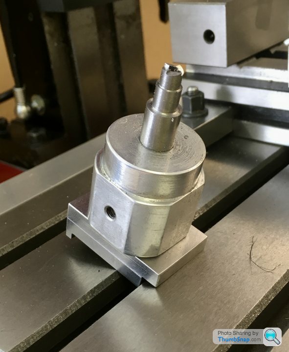
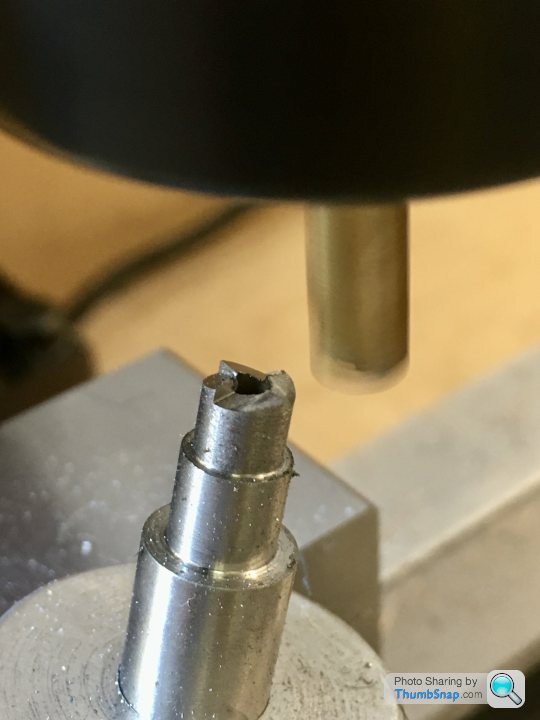
| Dr_GMJN | 22/05/2020 19:17:35 |
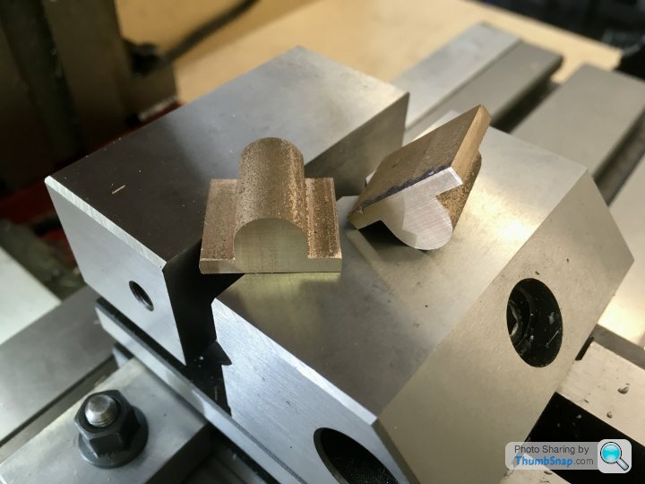
1602 forum posts | So today I re-made the spot facing tool, this time in Silver Steel from M-Machine, rather than Stainless (which I used by mistake last time). I've put all my known and marked steels in a box, the rest I've kept in reserve in 'deep storage' (the shed) just in case. |
| Dr_GMJN | 23/05/2020 09:45:57 |
1602 forum posts | Posted by Jon Cameron on 22/05/2020 11:21:44:
Hi, If I could direct you to Harold Halls page HERE, you'll see the best way i think to machine the bearings, cut them into two sections, mount in 3 jaw, with packing to protect them. Drill and bore, then mount onto a mandrel between centres for the boss to be turned to size. The bores are left undersize to begin with, they can be line bored to set the correct alignment once bolted into position. So yes bolt to the bedplate, then finish to size when all bolted together. It may well be prudent to gently centre punch the bearing and bedplate so that going forward to finish the build when they are taken out or put back together they always go into the correct place, and your not chasing your tail looking for fault when you assemble a new part thinking something isn't correct with it. (do it discreetly on the inside of the bed plate and bearing. one dot for left side two dots for right side). Jon Edited By Jon Cameron on 22/05/2020 11:26:36 Jon, I’ve read Hall’s method, but it’s a bit vague fair a beginner wanting to replicate it. For example - mounting on a mandrel - how to you stop the part from turning? Also, when assembled, the inner boss faces seem to provide the crankshaft end-float limit; am I better off leaving excess in the inners, and then finishing them to the crank web width later on? Thanks. |
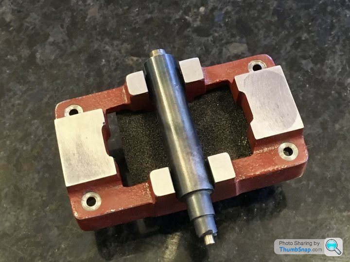
| Dr_GMJN | 23/05/2020 17:28:17 |
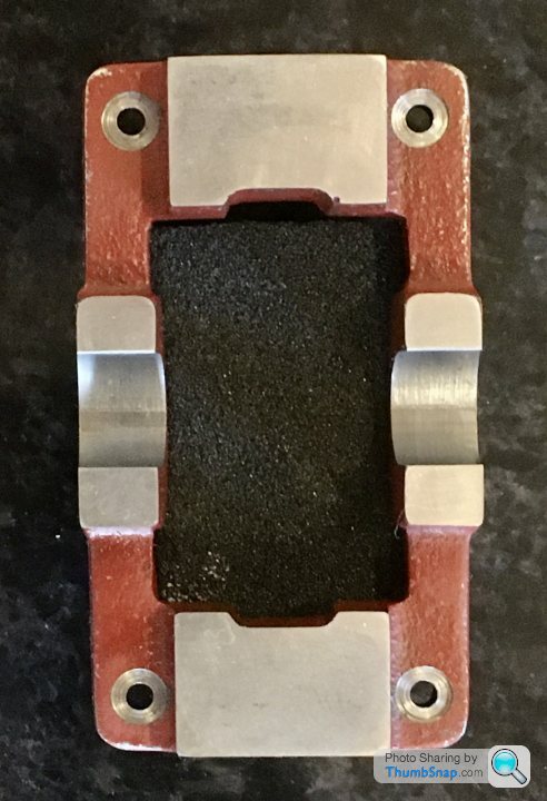
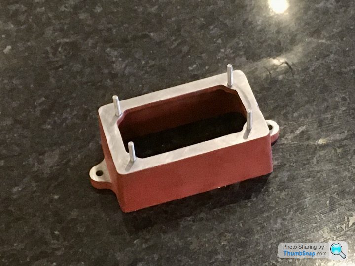
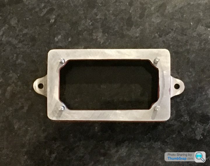
1602 forum posts | Still puzzling over how to retain the bearings on a mandrel and how to make a centering bar, so in the meantime I thought I'd finish the box bed. The mounting lugs are cast with dimples to drill to, but they didn't look central to me, and since thre are no dimensions given on the drawing I just got one with it the best I could. |
| Martin Connelly | 23/05/2020 20:26:48 |
 2549 forum posts 235 photos | Turning between centres using a mandrel requires a tapered mandrel. You can make your own, the taper is created by setting the tailstock slightly off centre. There is a standard taper for such things, it is a few thou per inch but I can't recall the proper value as I have not made one or used one. I'm sure some in the forum have made them but a google search should turn up an answer. You can also get expanding mandrels but they are only worth buying if you are going to use them a lot or can get them cheaper than a bit of bar. There will be instructions on using them somewhere on line but basically push the part down the taper until it locks in position. Big steel parts could be heat shrunk on or hydraulically pressed on or off. Small brass parts a gentle tap should be all that is required but don't take deep cuts. Also the direction of cut should be the direction that pushes the part further onto the taper. Martin C |
| JasonB | 23/05/2020 20:43:49 |
25215 forum posts 3105 photos 1 articles | For small beaings and such parts like this your arbor or mandrel can take many forms. 1. Most simple is to put a piece of bar into the chuck and turn to a good firm fit in your bearing and then slip the bearing on with a small amount of loctite or superglue, once machined heat will break the bond. The downsid eto this method with four ends to do is that you have to remove the mandrel each time to heat, it can be marked so it goes back in the same way but not ideal to remove it.
2. Similar to above but turn the spigot that fits into the hole about 2/3rds its length but put a very slight say 1 deg taper on the rest so the diameter increases towards the chuck. You can then slip the bearing onto the parallel part and then wring it onto the taper with a slight twisting action, if light cuts are used it will hold and the part can be wrung off again so mandrel stays put ensuring it's concentric. 3. Again turn a spigot to a good firm fit in the bearing and just shorter than it then drill and tap the end for a bolt or screw to retain the bearing, M5 with a cap head screw would work nicely on these bearings as screw head is just under the diameter you want to turn. Again mandrel does not need to come out of chuck. I'd go with this option.
4. Turn spigot to full length or a bot longer, drill and tap with a taper tap so you get a few full turns of thread. Mark the bit of bar you are using so it can be removed from chuck and then saw down the middle of the spigot before putting back in chuck. You can now slip the bearing onto the spigot and wind in a screw which will expand the spigot as it gets to the tapered part of the thread.
I tend to use aluminium for these sort of things and you soon build up a collection that can be used again and again, maybe skimming down to the next size or shortening.
|


Please login to post a reply.
Magazine Locator
Want the latest issue of Model Engineer or Model Engineers' Workshop? Use our magazine locator links to find your nearest stockist!
Sign up to our Newsletter
Sign up to our newsletter and get a free digital issue.
You can unsubscribe at anytime. View our privacy policy at www.mortons.co.uk/privacy
Latest Forum Posts
- *Oct 2023: FORUM MIGRATION TIMELINE*
05/10/2023 07:57:11 - Making ER11 collet chuck
05/10/2023 07:56:24 - What did you do today? 2023
05/10/2023 07:25:01 - Orrery
05/10/2023 06:00:41 - Wera hand-tools
05/10/2023 05:47:07 - New member
05/10/2023 04:40:11 - Problems with external pot on at1 vfd
05/10/2023 00:06:32 - Drain plug
04/10/2023 23:36:17 - digi phase converter for 10 machines.....
04/10/2023 23:13:48 - Winter Storage Of Locomotives
04/10/2023 21:02:11 - More Latest Posts...
- View All Topics
Support Our Partners


Shopping Partners
Subscription Offer

Latest "For Sale" Ads
- Reeves** - Rebuilt Royal Scot by Martin Evans
by John Broughton
£300.00 - BRITANNIA 5" GAUGE James Perrier
by Jon Seabright 1
£2,500.00 - Drill Grinder - for restoration
by Nigel Graham 2
£0.00 - WARCO WM18 MILLING MACHINE
by Alex Chudley
£1,200.00 - MYFORD SUPER 7 LATHE
by Alex Chudley
£2,000.00 - More "For Sale" Ads...
Latest "Wanted" Ads
- D1-3 backplate
by Michael Horley
Price Not Specified - fixed steady for a Colchester bantam mark1 800
by George Jervis
Price Not Specified - lbsc pansy
by JACK SIDEBOTHAM
Price Not Specified - Pratt Burnerd multifit chuck key.
by Tim Riome
Price Not Specified - BANDSAW BLADE WELDER
by HUGH
Price Not Specified - More "Wanted" Ads...
Get In Touch!
Do you want to contact the Model Engineer and Model Engineers' Workshop team?
You can contact us by phone, mail or email about the magazines including becoming a contributor, submitting reader's letters or making queries about articles. You can also get in touch about this website, advertising or other general issues.
Click THIS LINK for full contact details.
For subscription issues please see THIS LINK.
Digital Back Issues


Donate

 Register
 Log-in
Model Engineer Magazine
- Percival Marshall
- M.E. History
- LittleLEC
- M.E. Clock

ME Workshop
- An Adcock
- & Shipley
- Horizontal
- Mill

Subscribe Now
- Great savings
- Delivered to your door

Pre-order your copy!
- Delivered to your doorstep!
- Free UK delivery!
All Forum Topics > Work In Progress and completed items > Stuart 10V Build Log - Complete Beginner...