Forum sponsored by:

Graham Meek?s Tailstock Dial - MEW279
Drawing errors
| Graham Meek | 03/04/2020 13:25:37 |
| 714 forum posts 414 photos | Given the feed back that I have received from constructors of this attachment, this has not been a problem. The Input gear is larger in diameter that the Thrust race, thus the face of the Idler gear teeth, above the pitch diameter, enter a pocket and just kiss the face of the Thrust race. Provided the drawing dimensions are adhered to this will not cause a problem. The Idler gear floats on the Idler pin so there is no end loading forcing the gear to contact the Thrust race. Regards Gray,
|
| Brian Abbott | 03/04/2020 20:54:09 |
 523 forum posts 95 photos | Thanks Graham I can see what you're saying, would you have a photo of the gear cutting bits, or the setup you used? Thanks, Brian
|
| Graham Meek | 04/04/2020 11:35:03 |
| 714 forum posts 414 photos |
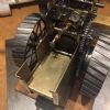
The jig above is for 1/8" and 3/16" square Silver Steel, (if you can get hold of it), or Gauge Plate, better known as Ground Flat Stock these days. The centre line of each blank is 12 mm from the fixed Jaw face of my Machine vice. As I always work with this face set to Zero I know exactly where each cutter is in relation to my index.
This is a sequence of photographs showing how I go about making a gear cutter. IN this case this is a special for a Centring Device I made some years ago. I think the Gear was 0.4 MOD. The cutters in the jig are inclined at an angle of 10 degrees to the Horizontal.
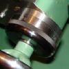
These last three images show how the gear form is created using in this instance a 1/16" Slot Drill. Most of my cutters are made double ended, that way should I have a calamity I can quickly change the cutter end for end. I have a photograph somewhere of how I hold the cutters in the mill. Regards Gray, |
| Graham Meek | 04/04/2020 11:43:19 |
| 714 forum posts 414 photos | I have found the photographs quicker than I thought,
The above was when I made the sample Super 7 Handwheel dials for the original article in EiM. This cutter incidentally had been used to produce approx 500 dials over the course of 30 years. The cutter only requires touching up on the top surface to restore the cutting edge. Regards Gray, |
| Circlip | 04/04/2020 12:35:36 |
| 1723 forum posts | "Good in principle, in practice often impractical as deadlines are tight and I would also need extra time for corrections to be made" If Microsloth can't get it right after decades of practise, - - - - - -
Regards Ian. |
| Graham Meek | 04/04/2020 14:27:49 |
| 714 forum posts 414 photos | Posted by Circlip on 04/04/2020 12:35:36:
"Good in principle, in practice often impractical as deadlines are tight and I would also need extra time for corrections to be made" If Microsloth can't get it right after decades of practise, - - - - - -
Regards Ian. Being a thick Forester I regret to say you will need to explain this post? I am assuming it was intended for another Topic? Regards Gray, |
| Brian Abbott | 04/04/2020 20:22:30 |
523 forum posts 95 photos | Hello Graham. Really appreciate the photos, thank you. Notice you have cut the slit in the slave gear before cutting the teeth, this is usefull to know. Thanks again. |
| Graham Meek | 05/04/2020 10:42:40 |
| 714 forum posts 414 photos | Hello Brian, The sleeve gear is easier to hold without the teeth on, and less likely to distort as the teeth remove a lot of material from the end face. This face is used to clamp the part for slitting in the appropriate fixture. What is not shown in the photograph is a small locating dowel to locate the axial slit of the sleeve gear. The dividing head was set using a flat on the mandrel, (also not shown),so that a tooth space on the sleeve gear aligned with the slit. Its a case of me just being fussy, I guess. Regards Gray, |
| Brian Abbott | 07/04/2020 20:44:53 |
523 forum posts 95 photos | Thanks Graham. |
| Martin Kyte | 07/04/2020 22:15:49 |
 3445 forum posts 62 photos | Could someone point me in the right direction of a supplier for the thrust bearings please. regards Martin |
| Steamer1915 | 08/04/2020 11:48:15 |
 171 forum posts 42 photos | Martin, PM sent. Best regards, Steve. |
| Brian Abbott | 25/04/2020 20:28:48 |
523 forum posts 95 photos | Well..this is my interpretation of the Graham Meek designed tail stock gauge. I really enjoyed making this, nice little project. Thanks Graham.
|
| Steamer1915 | 25/04/2020 20:32:21 |
171 forum posts 42 photos | Nice work there Brian, Let's see a picture of it on the tailstock!
Steve.
|
| Graham Meek | 26/04/2020 10:47:11 |
| 714 forum posts 414 photos | Hi Brian, You are entirely welcome, I hope you have many happy hours using this attachment in the future. My best regards Gray, |
| Brian Abbott | 26/04/2020 23:32:29 |
523 forum posts 95 photos | Hello Steve Photo of the gauge attached, i would have liked to have chemically blacked it to match the saddle gauge i bought from you some time ago but didn’t know how to do it, either way certainly looks the part and will be very useful. Thanks again Brian
Edited By Brian Abbott on 26/04/2020 23:33:14 |
| Steamer1915 | 27/04/2020 08:40:53 |
171 forum posts 42 photos | That looks good Brian, It might be to your advantage to fill the lines and numbers with black paint. Just a thought.
Best regards, Steve. |
| Circlip | 27/04/2020 10:47:34 |
| 1723 forum posts | "Being a thick Forester I regret to say you will need to explain this post? I am assuming it was intended for another Topic?" Was a reply to Neil's comment of the 29/3/20 of "Tight" deadlines. Reference to "Sloth" was the Tuesday "Updates" to their O/S. Escape of drawing errors is not new, hence the number of complaints by the great unwashed being unable to understand why no one has corrected some/many existing designs. Sorry for the side track, seemed pertinent at the time.
Regards Ian. Edited By Circlip on 27/04/2020 10:56:19 |
| Graham Meek | 27/04/2020 16:39:00 |
| 714 forum posts 414 photos | Ian, Thanks for the explanation all has become clear, I was beginning to think I was losing what bit of sense I have. Regards Gray, |
| Martin Kyte | 14/05/2020 12:55:45 |
3445 forum posts 62 photos | Haha, finished finally. Don't know if this was intended or just a happy accident but the holes for the pin spanner are identical to the ones in the small bore adjusting collar on the end of the spindle so the Myford peg spanner fits a treat.
|
| Steamer1915 | 14/05/2020 13:14:49 |
171 forum posts 42 photos | Nice work there Martin.
Steve. |


Please login to post a reply.
Magazine Locator
Want the latest issue of Model Engineer or Model Engineers' Workshop? Use our magazine locator links to find your nearest stockist!
Sign up to our Newsletter
Sign up to our newsletter and get a free digital issue.
You can unsubscribe at anytime. View our privacy policy at www.mortons.co.uk/privacy
Latest Forum Posts
- *Oct 2023: FORUM MIGRATION TIMELINE*
05/10/2023 07:57:11 - Making ER11 collet chuck
05/10/2023 07:56:24 - What did you do today? 2023
05/10/2023 07:25:01 - Orrery
05/10/2023 06:00:41 - Wera hand-tools
05/10/2023 05:47:07 - New member
05/10/2023 04:40:11 - Problems with external pot on at1 vfd
05/10/2023 00:06:32 - Drain plug
04/10/2023 23:36:17 - digi phase converter for 10 machines.....
04/10/2023 23:13:48 - Winter Storage Of Locomotives
04/10/2023 21:02:11 - More Latest Posts...
- View All Topics
Support Our Partners


Shopping Partners
Subscription Offer

Latest "For Sale" Ads
- Reeves** - Rebuilt Royal Scot by Martin Evans
by John Broughton
£300.00 - BRITANNIA 5" GAUGE James Perrier
by Jon Seabright 1
£2,500.00 - Drill Grinder - for restoration
by Nigel Graham 2
£0.00 - WARCO WM18 MILLING MACHINE
by Alex Chudley
£1,200.00 - MYFORD SUPER 7 LATHE
by Alex Chudley
£2,000.00 - More "For Sale" Ads...
Latest "Wanted" Ads
- D1-3 backplate
by Michael Horley
Price Not Specified - fixed steady for a Colchester bantam mark1 800
by George Jervis
Price Not Specified - lbsc pansy
by JACK SIDEBOTHAM
Price Not Specified - Pratt Burnerd multifit chuck key.
by Tim Riome
Price Not Specified - BANDSAW BLADE WELDER
by HUGH
Price Not Specified - More "Wanted" Ads...
Get In Touch!
Do you want to contact the Model Engineer and Model Engineers' Workshop team?
You can contact us by phone, mail or email about the magazines including becoming a contributor, submitting reader's letters or making queries about articles. You can also get in touch about this website, advertising or other general issues.
Click THIS LINK for full contact details.
For subscription issues please see THIS LINK.
Digital Back Issues


Donate

 Register
 Log-in
Model Engineer Magazine
- Percival Marshall
- M.E. History
- LittleLEC
- M.E. Clock

ME Workshop
- An Adcock
- & Shipley
- Horizontal
- Mill

Subscribe Now
- Great savings
- Delivered to your door

Pre-order your copy!
- Delivered to your doorstep!
- Free UK delivery!
All Forum Topics > Model Engineers' Workshop. > Graham Meek?s Tailstock Dial - MEW279