Forum sponsored by:

Os Gemini twin glow engine - conrod req'd - no longer made
| dean clarke 2 | 15/01/2018 23:15:59 |
 169 forum posts 330 photos | OK so on with the show................... outside profiling under way
next its onto radiusing the little end and the outside flanges of the big end, although as I have a few other conrods to get to this stage before taking the machine vise off it may be a few days before more swarf is made from these blanks. Cheers for now Dean |
| Michael Black 1 | 21/01/2018 22:45:22 |
| 13 forum posts | Nearly missed this update looking good, strange how big they look I know they are small great work Dean 👍 Edited By Michael Black 1 on 21/01/2018 22:49:43 |
| dean clarke 2 | 21/01/2018 23:34:07 |
169 forum posts 330 photos | HaHa, well they are in fact fairly big compared to what I normally make, I'll post a photo showing your rods compared to some for the engines I'm currently building. cheers Dean |
| Howard Lewis | 23/01/2018 22:55:08 |
| 7227 forum posts 21 photos | Introducing some pedantry, IDEALLY when the rods are fitted, the big ends should be tightened to the same torque as that used when they were machined. Taken as read that the caps will be assembled oriented as they were whilst being machined. In this size, difficult to measure to measure the torque, without rather special torque spanners for low torques, or you could use a spring balance on an arm of known length. In an ideal world, even after machining the bores, they could be measured with a bore set, or something of that nature and torqued in stages until as round as possible, and the figures noted. During assembly, the fixings are then tightened to the figures noted for each fixing. (That's what i did for an engine for a sports/racing car) The reason for this procedure is that if the torque applied during assembly differs from that when the bore was machined, the resulting bore will be oval. The plane of the major axis of the oval will depend on whether the fixings have been under or over torqued compared to that applied before machining. The devil is in the detail, but it does make a difference to output and life expectancy! Howard
|
| dean clarke 2 | 31/01/2018 18:52:46 |
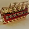
169 forum posts 330 photos | So here's a quick photo update to show the comparison of the OS Gemini rod to one from my latest Supercharged two stroke V8 project
So anyone know the torque settings for an m2 big end bolt or perhaps the torque setting for the 0/80 bolt used on my V8 rods, I generally just use the torque setting of T.E. but not the F.T or E.F.T. and I've found that using the tightening instructions of " tighten till it shears and back off half a turn " doesn't really go to well either. i'm fairly certain that foot pounds and inch pounds torque on either of these bolts would result in the sheared off torque setting and that would be a bit of a waste of time. so anyone got any bright idea's. LOL (i'm kidding of course, no-one torques small model engine bolts, you don't have the same distortion when machining as in full size practice, well nothing that's actually measurable anyway.) cheers Dean
|
| John Olsen | 01/02/2018 08:36:43 |
| 1294 forum posts 108 photos 1 articles | Try this chart: No doubt the ordinary torque wrench will not be sensitive enough, but there will be an optimum torque even for small screws. "Do it up until it strips" is really meant for British motorcycles, where it is going to rattle undone anyway. (As is "If it moves, weld it, if it doesn't move, get a bigger hammer."
|
| Tim Stevens | 01/02/2018 12:42:14 |
 1779 forum posts 1 photos | The distortion from under or over torqueing will depend largely on the flatness of the mating surfaces. If it is possible to get these surfaces lapped wonderfully flat before the final boring operation, there is much less chance of distortion on final assembly. There is a dowel or similar, isn't there? Just a thought - Tim Edited By Tim Stevens on 01/02/2018 12:43:09 |
| Martin 100 | 01/02/2018 17:57:06 |
| 287 forum posts 6 photos | Posted by Howard Lewis on 23/01/2018 22:55:08:
In this size, difficult to measure to measure the torque, without rather special torque spanners for low torques There are plenty of torque screwdrivers that work down to 1Nm or less, some with interchangeable tips
|
| dean clarke 2 | 07/02/2018 02:40:56 |
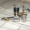
169 forum posts 330 photos | O.k. here is the latest on these rods. below shows the progress
And.... all finished
You may want to polish the crankshaft mick to ensure a good running surface, also double check the diameter before I post them back to you and let me know, should be a nominal 10mm or 9.98ish. Oh and also don't forget to torque the big ends down to the correct setting, which is 0.35nm cheers Dean |
| Danny M2Z | 07/02/2018 05:13:19 |
 963 forum posts 2 photos | Posted by Martin 100 on 01/02/2018 17:57:06:
Posted by Howard Lewis on 23/01/2018 22:55:08:
In this size, difficult to measure to measure the torque, without rather special torque spanners for low torques There are plenty of torque screwdrivers that work down to 1Nm or less, some with interchangeable tips Here is another, it's quite affordable and useful for my target rifles as well as fasteners on my model engines. 0.35 Nm is about 50 oz-in, so within it's range **LINK** * Danny M * |
| Michael Black 1 | 07/02/2018 20:19:55 |
| 13 forum posts | Nearly missed this again thanks dean looking great. The crank is 10mm and I wil make sure I polish and torque down when installed. Really excited to see them in the flesh as they say. Mick Edited By Michael Black 1 on 07/02/2018 20:22:05 |
| dean clarke 2 | 07/02/2018 23:12:45 |
169 forum posts 330 photos | No Problem, will pop them in the post this weekend, sorry it took so long mate but we got there in the end. Cheers Dean |
| Fernando Giaccaglia | 19/09/2022 00:40:47 |
| 1 forum posts | Hello, And sorry for resuscitating an old thread. As you can see this is my very first post here, I just bumped into this thanks to google so I decided to join and ask... I just got a O.S.FT-240 Gemini that I'm thinking in converting it to petrol and it has the infamous aluminium (bronze coloured) old conrods. I read about them failing but I'm not sure how serious the issue is. I do have a small milling machine and some (very little) machining experience so I wonder if I should get some 7075 Al and try to machine a pair or just run the original ones??? I'm afraid that if they fail the damage could involve other parts that are also extinct. I saw a video from a guy in Switzerland (very professional looking job) also the pics here from Dean that looks like he took a slightly different approach to it so is nice when you see things made in different ways, at least makes me feel more encouraged to give it a try. I'd appreciate any input from anyone with experience on either these engines or machining these. I don't know how precise my mill is (just blame it to the machine) coupled to my limited experience. The biggest brake I find is that I might be missing some very precise measuring tools, I do have the basic stuff (calipers, indicator, regular 0.01 micrometer, and that's about it) Thanks, Fernando |


Please login to post a reply.
Magazine Locator
Want the latest issue of Model Engineer or Model Engineers' Workshop? Use our magazine locator links to find your nearest stockist!
Sign up to our Newsletter
Sign up to our newsletter and get a free digital issue.
You can unsubscribe at anytime. View our privacy policy at www.mortons.co.uk/privacy
Latest Forum Posts
- hemingway ball turner
04/07/2025 14:40:26 - *Oct 2023: FORUM MIGRATION TIMELINE*
05/10/2023 07:57:11 - Making ER11 collet chuck
05/10/2023 07:56:24 - What did you do today? 2023
05/10/2023 07:25:01 - Orrery
05/10/2023 06:00:41 - Wera hand-tools
05/10/2023 05:47:07 - New member
05/10/2023 04:40:11 - Problems with external pot on at1 vfd
05/10/2023 00:06:32 - Drain plug
04/10/2023 23:36:17 - digi phase converter for 10 machines.....
04/10/2023 23:13:48 - More Latest Posts...
- View All Topics
Support Our Partners


Shopping Partners
Subscription Offer

Latest "For Sale" Ads
- Reeves** - Rebuilt Royal Scot by Martin Evans
by John Broughton
£300.00 - BRITANNIA 5" GAUGE James Perrier
by Jon Seabright 1
£2,500.00 - Drill Grinder - for restoration
by Nigel Graham 2
£0.00 - WARCO WM18 MILLING MACHINE
by Alex Chudley
£1,200.00 - MYFORD SUPER 7 LATHE
by Alex Chudley
£2,000.00 - More "For Sale" Ads...
Latest "Wanted" Ads
- D1-3 backplate
by Michael Horley
Price Not Specified - fixed steady for a Colchester bantam mark1 800
by George Jervis
Price Not Specified - lbsc pansy
by JACK SIDEBOTHAM
Price Not Specified - Pratt Burnerd multifit chuck key.
by Tim Riome
Price Not Specified - BANDSAW BLADE WELDER
by HUGH
Price Not Specified - More "Wanted" Ads...
Get In Touch!
Do you want to contact the Model Engineer and Model Engineers' Workshop team?
You can contact us by phone, mail or email about the magazines including becoming a contributor, submitting reader's letters or making queries about articles. You can also get in touch about this website, advertising or other general issues.
Click THIS LINK for full contact details.
For subscription issues please see THIS LINK.
Digital Back Issues


Donate

 Register
 Log-in
Model Engineer Magazine
- Percival Marshall
- M.E. History
- LittleLEC
- M.E. Clock

ME Workshop
- An Adcock
- & Shipley
- Horizontal
- Mill

Subscribe Now
- Great savings
- Delivered to your door

Pre-order your copy!
- Delivered to your doorstep!
- Free UK delivery!
All Forum Topics > I/C Engines > Os Gemini twin glow engine - conrod req'd - no longer made