Forum sponsored by:

13DP Gears or Gear Cutter
| Clive Foster | 27/04/2017 11:38:08 |
| 3630 forum posts 128 photos | Agree with John Stevenson and Howard Lewis that a "somewhere near" gear in delrin will almost certainly be more than adequate. Especially as the mating gears are almost certainly worn to some degree and therefore of less than perfect tooth form anyway. If you do want them a bit better maybe the shaper method could be used to shave the gear teeth to almost the true form. As you already have a gear to start with it can be self indexed for automatic rotation using a strip of two or three rack form teeth engaging opposite the cutter. I guess for absolute best results you'd need to go round twice as for the first half turn the rack will be engaging in slightly wrong shape teeth. Presumably creating a small error when the teeth on the opposite side of the gear are shaved. Second time round pretty much all of the error should have gone. Clearly way overkill here but possibly worth considering if inexpensive nylon or similar moulded gears can be found of suitable size and strength in the right tooth numbers but wrong form. Probably less trouble than setting up to cut from scratch and maybe a simpler technique for the neophyte who has no previous experience of gear cutting. Clive |
| John Stevenson | 27/04/2017 12:04:54 |
 5068 forum posts 3 photos | HPC at Chesterfield list Mod 2 gears in Nylon off the shelf, also list Tufnol if you want to use the cheque book engineering approach and get running faster ? |
| Circlip | 27/04/2017 12:16:50 |
| 1723 forum posts | "Keighly, land of the living dead." Worked there for years, 1000 reasons why you couldn't do something and not one why you could, bit frustrating after all the engineering excellence that once came out of the town. Prince Smith and Stells, Landis Lund and of course DSG.
Yorkshire manufactured Textile machinery, Hmm, nothing to do with buying the cheapest parts, One that I worked for in Cleckhuddersfax had it's own range of shaft sizes and bore dimensions for gears and chainwheels. This ensured that competitors gears etc. wouldn't fit so the customer had to come back to us for replacements so the size of the gear which "May Be Metric" ain't necessarily so, more than likely to be a silly b***er size for this reason.
Regards Ian.
Worth a try, there's an Industrial museum in Bradford and also Leeds that contain Textile machinery exhibits, may be worth a phone call to check if they have the specific machine. Edited By Circlip on 27/04/2017 12:25:58 |
| Bazyle | 27/04/2017 12:48:20 |
 6956 forum posts 229 photos | Is the large gear in the picture part of the same set? Measuring it would be less affected by any slight error in the original blank diameter and perhaps confirm the CP size suggestion. They might have used UNC at that time if they had bought up some war surplus nuts or threading tackle. When did the company fold? There could be some of the workers still around town who might even have made the specific loom. If it is a museum piece in which case some effort to use cast iron would be preferable or are you trying to compete with the Indian weavers post brexit? |
| James Jenkins 1 | 27/04/2017 15:43:19 |
 162 forum posts 7 photos | Hi all, Solved it! Managed to get hold of the original drawings for the change wheels and they were indeed 1/4" CP. Well deduced. Going to a have a think now about the best way forward. I don't need it immediately, so I have the luxury of a bit of thinking time. It even seems possible to make your own cutter. Got the book and so very helpful instructions emailed over. So lots to go on! Thanks for all your help everyone, really appreciated. James
|
| John Stevenson | 27/04/2017 23:49:48 |
5068 forum posts 3 photos | Firstly a good call by Niel A on the 0.25" CP form. Circular Pitch isn't used much nowadays and even when it was it was usually used on linear movement. DP always has Pi somewhere in the calculations but CP is a fixed linear move. Ideally racks on machine tools should be in CP as then the hand wheels will relate to proper numbers. a 16 tooth pinion in 0.25" CP will move exactly 4" per rev.
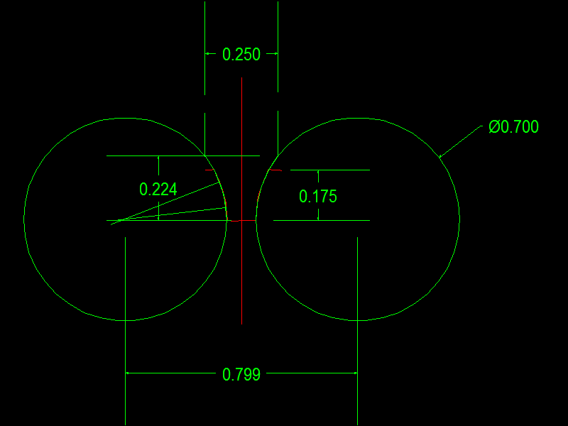
Anyway to get back to the original problem. If James wants to make a cutter using the method outlined in the Gears and Gear cutting book then the following diagram should help.
The red which is hard to see as the green overlays it is one tooth of a 37T gear @14.5 PA and 0.25" CP or 12.5664DP the circle on the left is how the size was drawn using two chords on the curve to find the centre and mirrored to the other side.
So James wants two buttons at 0.700" diameter, spaced at 0.799" apart and a blank cutter of 0.250" wide.
Once the buttons come into contact with the edges of the blank he needs to infeed 0.224" to form the shap but when cutting the gear he only needs to infeed the cutter 0.175" deep.
This is a slightly different way to how Ivan Law does it in the gears book. He touches the OD of the buttons on the face of the blank and then moves across, then feeds in.
The method above is the one devised by Grant in Victorian times and resurrected by Unwin in the 1980's. |
| James Jenkins 1 | 29/04/2017 10:39:25 |
162 forum posts 7 photos | Thank you so much for this John, really helpful! Looks like it's going to be an interesting project. James |
| Neil Wyatt | 29/04/2017 20:05:08 |
 19226 forum posts 749 photos 86 articles | You've averted a looming disaster!
IGMC Neil |


Please login to post a reply.
Magazine Locator
Want the latest issue of Model Engineer or Model Engineers' Workshop? Use our magazine locator links to find your nearest stockist!
Sign up to our Newsletter
Sign up to our newsletter and get a free digital issue.
You can unsubscribe at anytime. View our privacy policy at www.mortons.co.uk/privacy
Latest Forum Posts
- *Oct 2023: FORUM MIGRATION TIMELINE*
05/10/2023 07:57:11 - Making ER11 collet chuck
05/10/2023 07:56:24 - What did you do today? 2023
05/10/2023 07:25:01 - Orrery
05/10/2023 06:00:41 - Wera hand-tools
05/10/2023 05:47:07 - New member
05/10/2023 04:40:11 - Problems with external pot on at1 vfd
05/10/2023 00:06:32 - Drain plug
04/10/2023 23:36:17 - digi phase converter for 10 machines.....
04/10/2023 23:13:48 - Winter Storage Of Locomotives
04/10/2023 21:02:11 - More Latest Posts...
- View All Topics
Support Our Partners


Shopping Partners
Subscription Offer

Latest "For Sale" Ads
- Reeves** - Rebuilt Royal Scot by Martin Evans
by John Broughton
£300.00 - BRITANNIA 5" GAUGE James Perrier
by Jon Seabright 1
£2,500.00 - Drill Grinder - for restoration
by Nigel Graham 2
£0.00 - WARCO WM18 MILLING MACHINE
by Alex Chudley
£1,200.00 - MYFORD SUPER 7 LATHE
by Alex Chudley
£2,000.00 - More "For Sale" Ads...
Latest "Wanted" Ads
- D1-3 backplate
by Michael Horley
Price Not Specified - fixed steady for a Colchester bantam mark1 800
by George Jervis
Price Not Specified - lbsc pansy
by JACK SIDEBOTHAM
Price Not Specified - Pratt Burnerd multifit chuck key.
by Tim Riome
Price Not Specified - BANDSAW BLADE WELDER
by HUGH
Price Not Specified - More "Wanted" Ads...
Get In Touch!
Do you want to contact the Model Engineer and Model Engineers' Workshop team?
You can contact us by phone, mail or email about the magazines including becoming a contributor, submitting reader's letters or making queries about articles. You can also get in touch about this website, advertising or other general issues.
Click THIS LINK for full contact details.
For subscription issues please see THIS LINK.
Digital Back Issues


Donate

 Register
 Log-in
Model Engineer Magazine
- Percival Marshall
- M.E. History
- LittleLEC
- M.E. Clock

ME Workshop
- An Adcock
- & Shipley
- Horizontal
- Mill

Subscribe Now
- Great savings
- Delivered to your door

Pre-order your copy!
- Delivered to your doorstep!
- Free UK delivery!
All Forum Topics > General Questions > 13DP Gears or Gear Cutter