Forum sponsored by:

Jowitt MkII Popett Valve Engine Build
| JasonB | 21/03/2016 18:17:58 |
 25215 forum posts 3105 photos 1 articles | Good to see you are tempted Chris, its quite an enjoyable engine to build and does allow a bit of leway with how it is made. Indeed some people tend to spend their time looking for the elusive last 0.0001" but I prefer to get on and build something. Not to advocate sloppy work but a lot of the time super accuracy and fine limits are not needed.
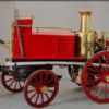
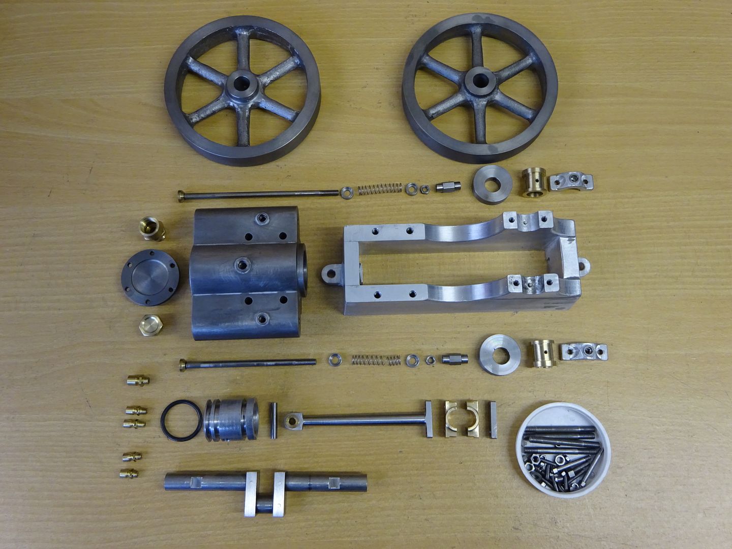
Piston At a shade under 24mm dia the piston will come nicely out of a piece of 25mm or 1" bar so pop a bit in the chuck with enough poking out for the part and turn down to the required 23.95mm which will leave a little room for the piston to expand due to the heat if you decide to run on steam. At the same setting the end can be faced off then starting with a spotting drill most of the waste can be drilled out to say 12mm before changing to a boring bar to open up the hole to the required 16mm dia by 24mm depth.
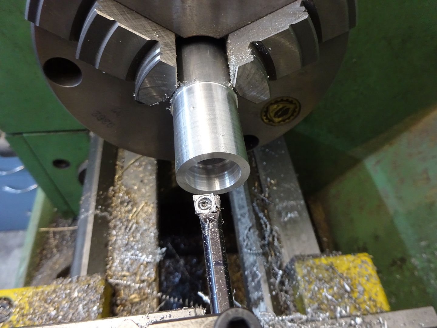
The piston ring grooves can also be added at this stage, I have given dimensions from the end of the piston to the left of the groove so simply touch the edge of the parting tool against the end of the piston and then wind the topslide along 8mm for the first groove and 26mm for the second. Bring the topslide back as you make a couple more parting cuts until the grooves are 2.6mm wide. Ease all the external corners so the O rings don't get nicked when fitting. You will notice that I cut 3 grooves as per Stan Bray's sketch but two will be quite adequate and is what I have shown on the drawings. My engine runs fine on air with just one ring in the groove furthest from the crank.
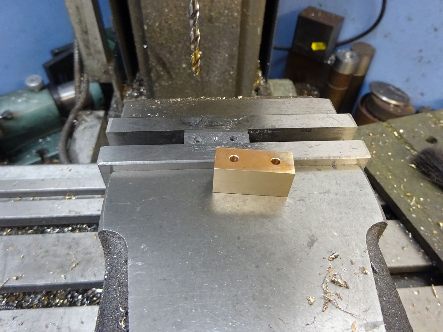
Over to the mill now, locate the centre of the piston dia, the ruler trick will do and then drill and ream a 4mm hole 17mm from the open end. I don't have many machine reamers but find that a hand reamer held in a collet and run at slow speed works perfectly well and in these sort of sizes tend to drill 0.2mm under dia so in this case drill 3.8mm.
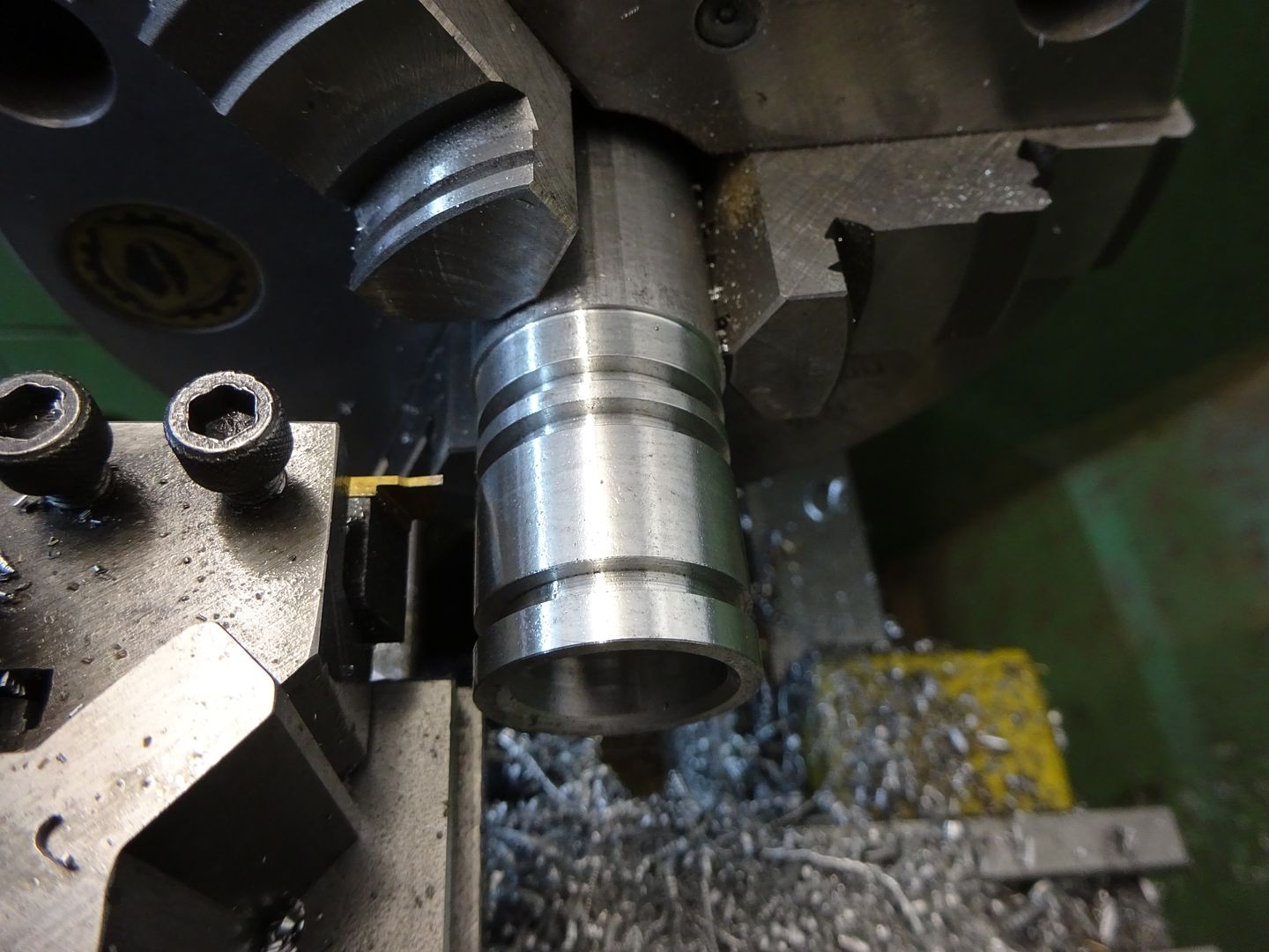
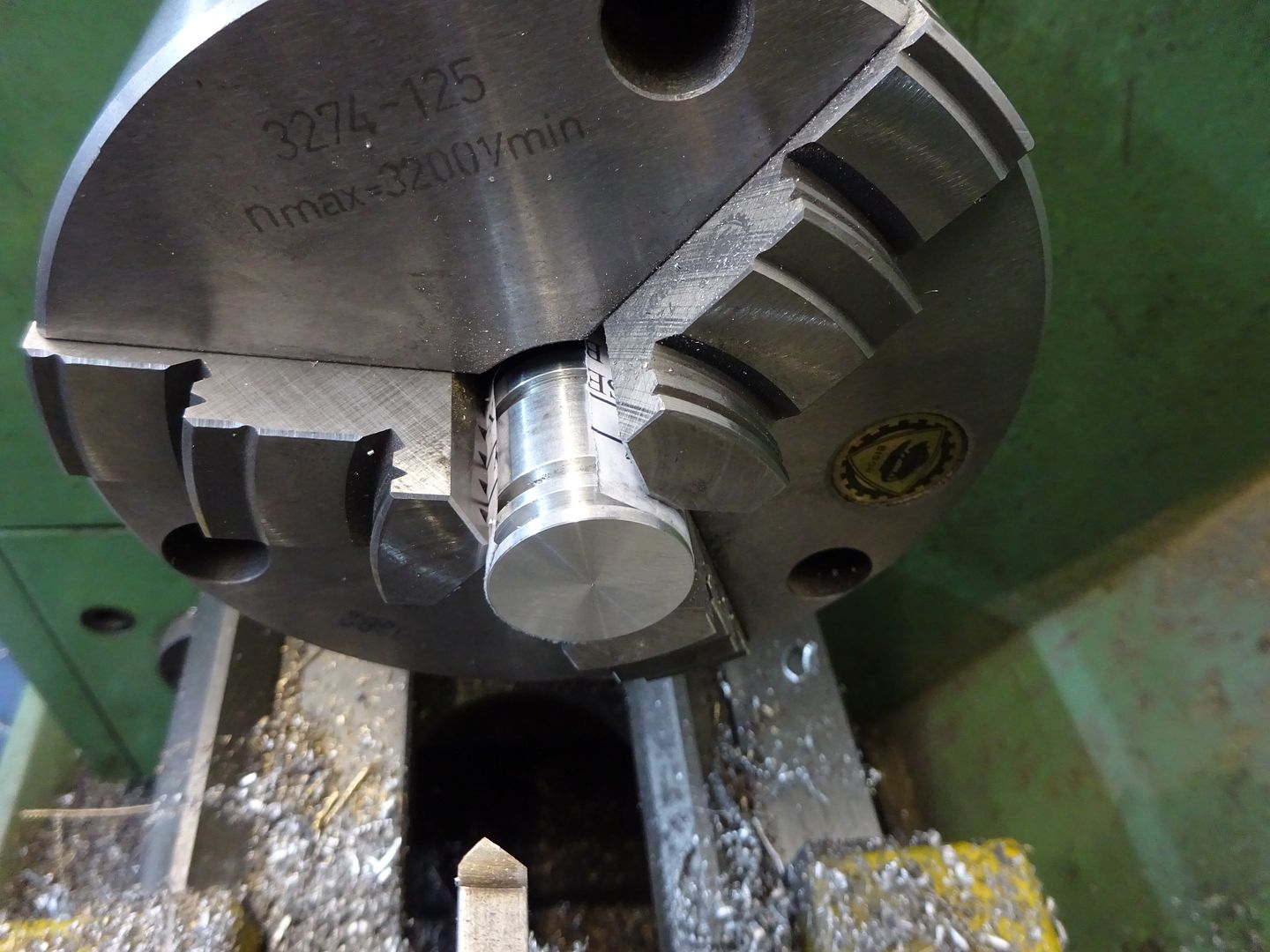
Saw or part off the piston a little over length then with something to protect the finished surface lightly hold in the chuck while the end is faced back to get the final 28mm length.
O-Rings I used Vitron O-rings: 19.6mm ID x 2.4mm section, bought on e-bay # 371503929586 Wrist Pin This is just a short length of 4mm silver steel (Drill Rod) faced to 21mm long and with a 2mm dia x 5mm deep hole in each end. Wrist Pin Pads These can be from Acetal, nylon, or any other similar material or bronze if you prefer doing them in metal so long as it is softer than the iron so they protect the bore from the wrist pin. Turn a short length to 4mm and then the 2mm spigot and finally part off to give a 1mm thick head.
J |
| JasonB | 31/03/2016 19:15:14 |
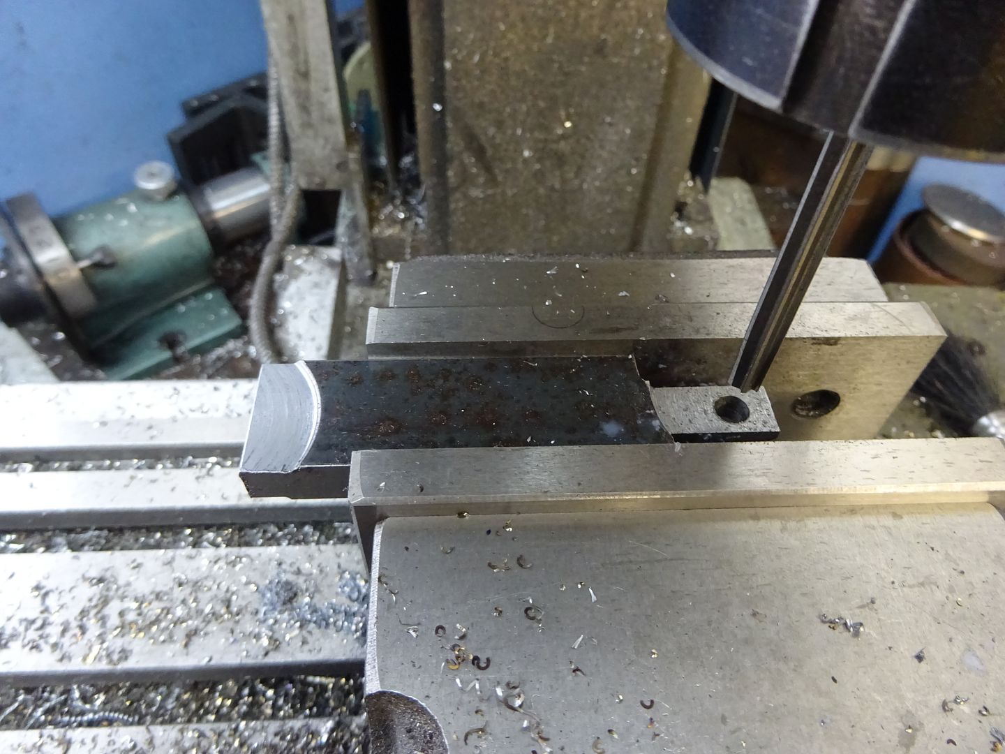
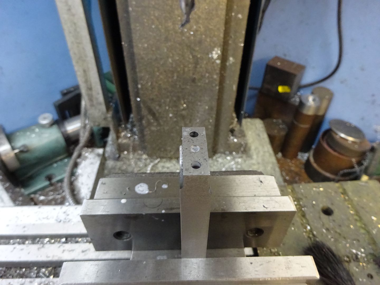
25215 forum posts 3105 photos 1 articles | Conrod I used a piece of 12x25mm black mild steel bar for this a few mm longer than the finished size. Start by maching one end down to 10x22mm and then the other to 6x10mm, square off the 10x22 end and then drill and ream 6mm dia 80mm from that end.
Put a small BS0 centre drill hole in each end and also drill the two 3mm holes in the big end.
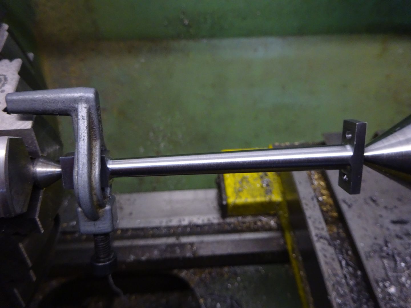
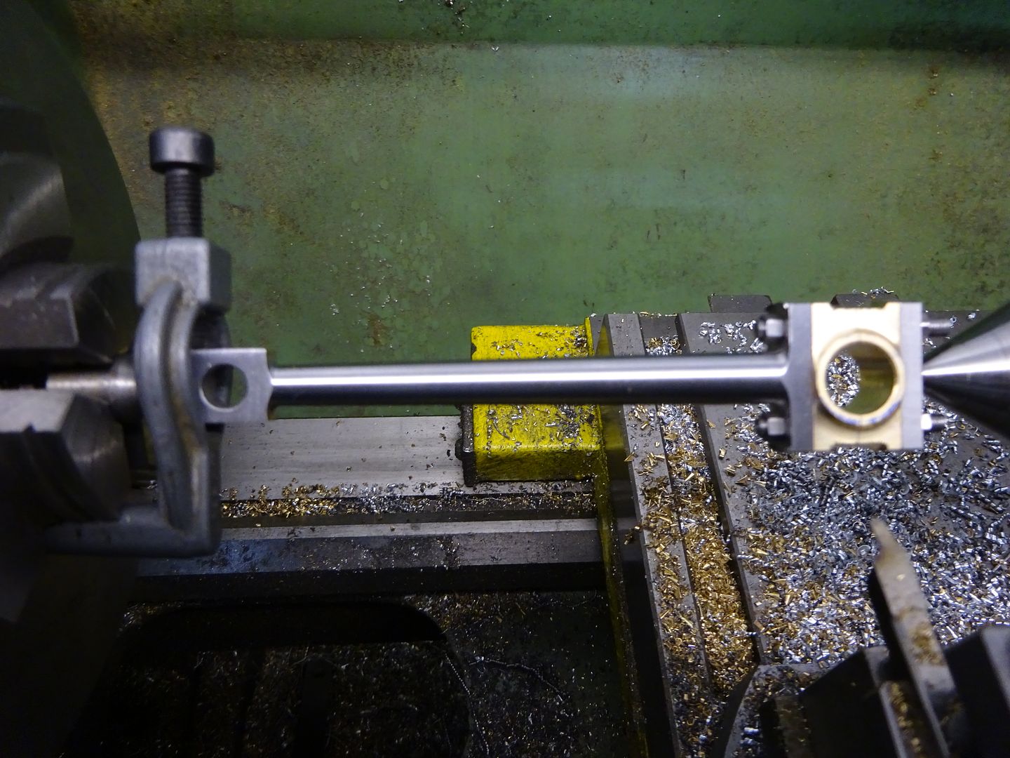
Use a hack saw to remove most of the waste then set up on the lathe between centres, firstly rough the rod down until its parallel and a little over 8mm then set the topslide over and finish to the final taper going from 8mm down to 6mm with a round nose tool.
Finally the small end can be rounded over which wil remove the ctr drill hole Big End Bearings and Keep Plate I will describe these together as some of the work can be done on both at the same time. For the bearings machine two pieces of bronze to 6mm thick and then soft solder together, once cool machine the pair to the final 22mm x 12mm. I find it easier this way than trying to line up two pieces that are finished size when soldering. The keep plate is just a piece of 3mm thick material machined to 10mm x 22mm. Drill the 3mm holes and include another small ctr drill hole in the keep plate.
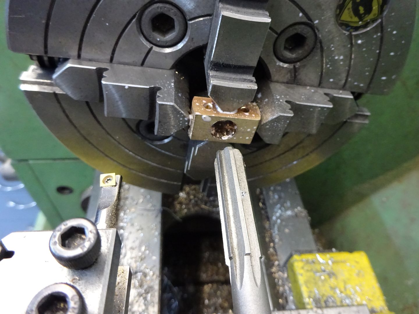
Lightly hold the two bearing halves in the 4-jaw and drill, bore then ream out to 10mm. Take it easy when drilling the hole as a blunt drill can expand pop the solder drill apart, you may notice from the splashes that I have also used some soluable oil which helps keep the heat down when drilling and reaming bronze, general turning can be done dry.
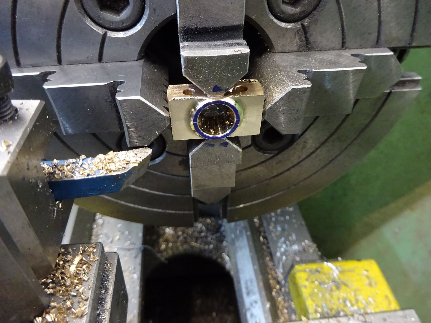
A small round nose tool can then be used to remove 1mm of material on each side blending nicely into the 12mm dia.
The parts so far can be assembled with a couple of temporary nuts and bolts, held between ctrs and then the big end turned down to 22mm dia and the round nosed tool used again to cut the 20mm dia waist in the bronze. Mark the parts so they can go back together the same way. Unsolder the bearings and give the mating faces a light rub on some wet & dry.
Small End Bearing This is a straight forward turning job, the bearing can be pressed or loctited into the conrod. Finally thread the ends of a couple of bits of 3mm rod and add a nut each end to hold things together. Test the fit on the crankshaft as the bearings may have closed up a bit when the solder was cleaned off, if so just run the reamer through again.
J |
| JasonB | 10/04/2016 19:49:21 |
25215 forum posts 3105 photos 1 articles | Valve Parts
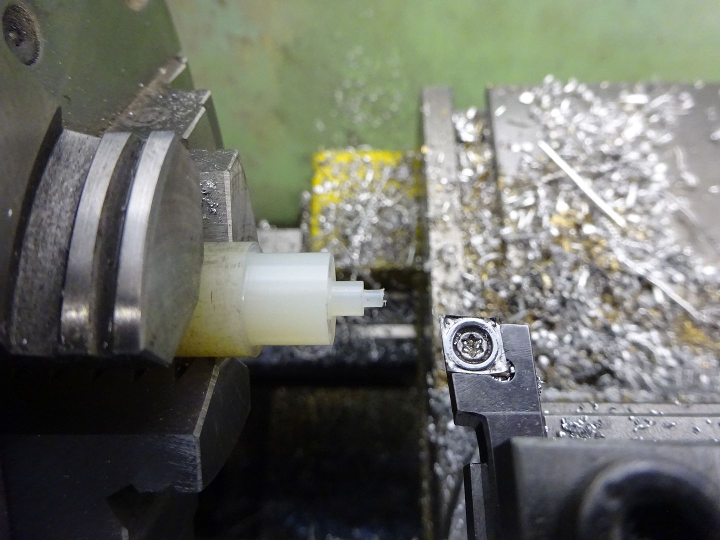
Inlet & Exhaust Rods These are just lengths of 303 Stainless steel faced off to there respective lengths. Thread one end of each M4 x 4mm long for the valve head and the other M4 x 10mm long to allow adjustment of the cam follower. Valve Heads Drill and thread some 8mm dia brass M4 and then cut the 45deg seat, part off and repeat. I find it easier to use a boring bar on the rear of the work with the lathe running in reverse as its easier than reaching across the lathe to turn the topslide handle especially on a job like this where a good finish is needed if the valves are to seal. The heads should be screwed onto the valve rods with a small amount of thread lock.
Cam Followers Face off two bits of 6mm hex steel 16mm long making sure the end that will run against the cam has a nice smooth finish. Turn down each end to 5.5mm diameter for a length of 4mm and then drill and tap M4 x 12mm deep. Lock Nuts These can be made from the same 6mm hex steel or you could use off the shelf M4 nuts and reduce their thickness. Spring Collars Face some 8mm dia steel, drill 4mm through and then form the recess for the spring with a 6mm milling cutter, part off and repeat for the other 3 collars.
Springs I have a couple of boxes of assorted springs which these came from, you want quite a soft spring approx 6mm OD, 25mm free length and 0.4mm wire thickness. Just enough to keep the valve closed but not offer too much resistance as the cam compresses them. All the above parts for one side of the engine.
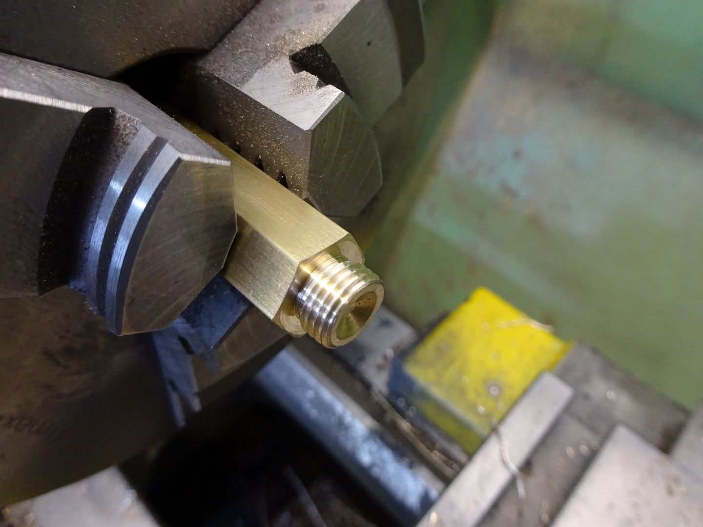
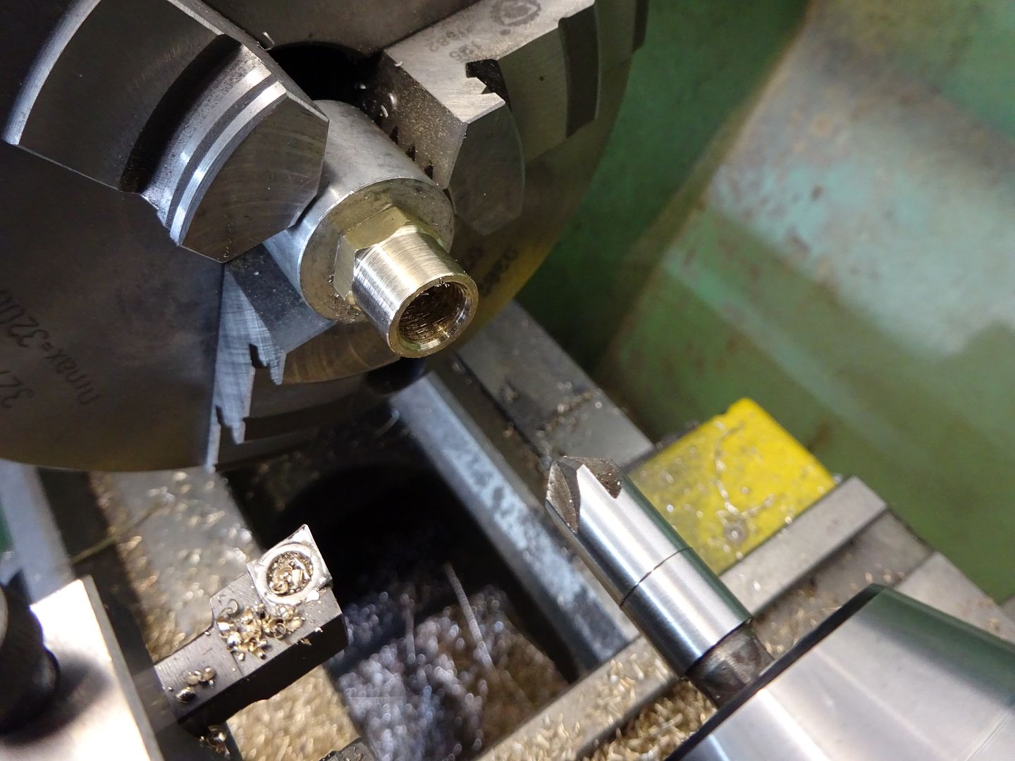
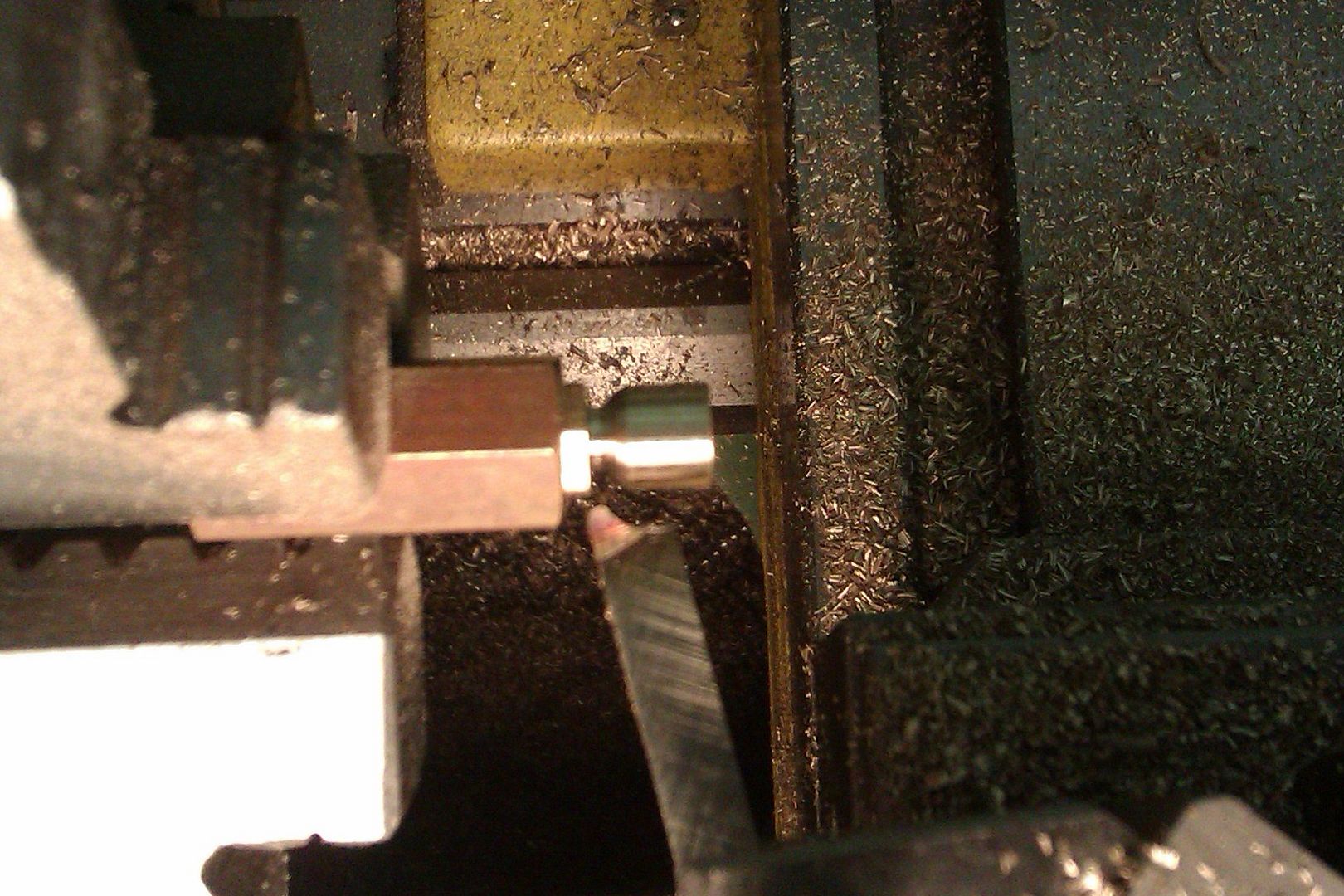
Exhaust Plug Turn a spigot on the end of some 13mm or 1/2" brass rod and thread M10 x 1 or whatever thread you used on the cylinder, part off and then clean up the head with a light chamfer to the corners.
Inlet Seat This is very similar to the Exhaust plug but should be parted off longer. Dril through 6mm dia and then open out and thread for your air/steam fitting, (1/8" BSP fits well). The bottom of this threaded hole should have a 45degree seat cut in a similar way to that of teh exhaust seat in the cylinder.
The two parts in place
J Edited By JasonB on 10/04/2016 19:49:45 Edited By JasonB on 17/04/2016 17:20:15 |
| JasonB | 17/04/2016 19:17:33 |
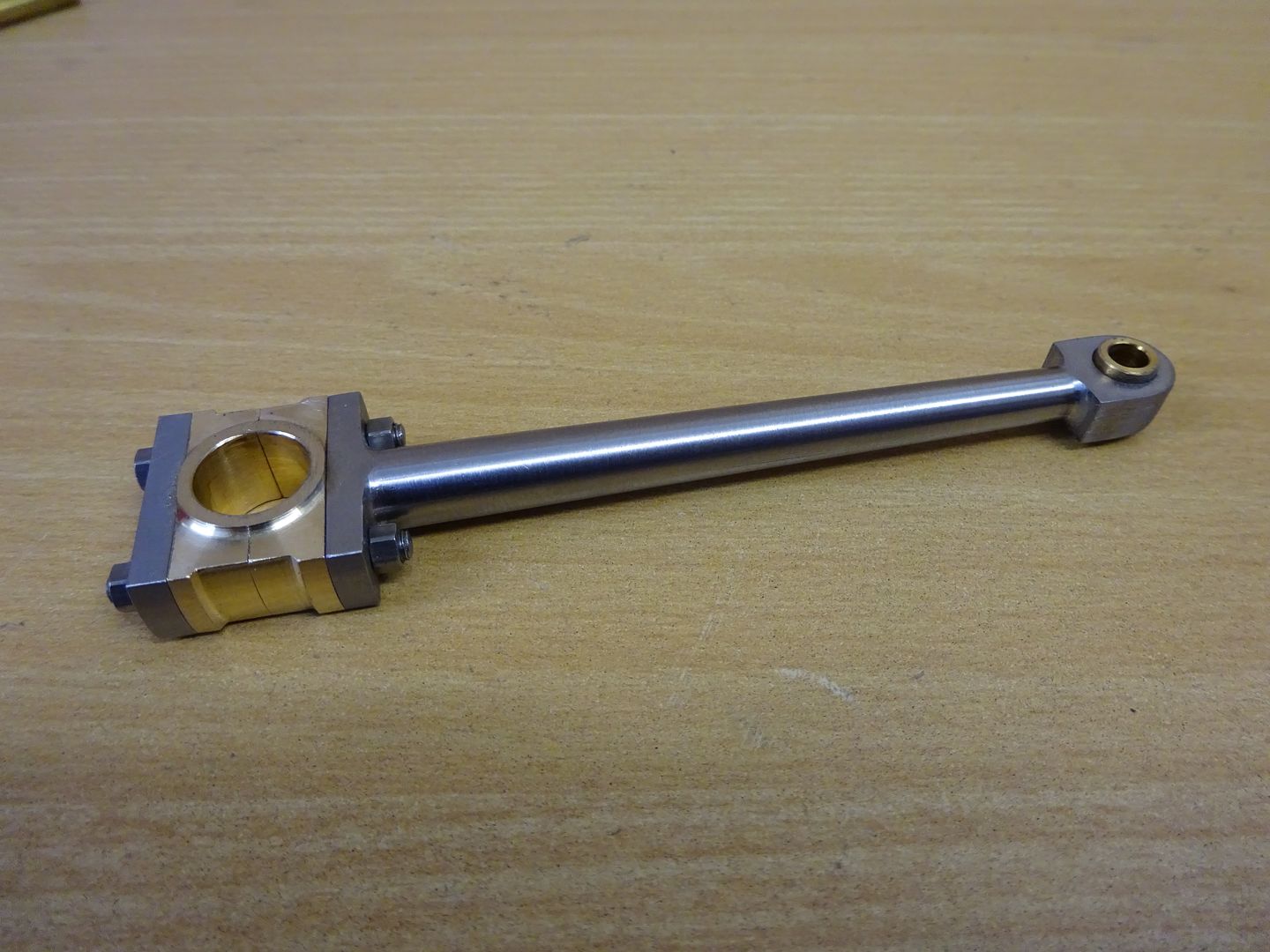
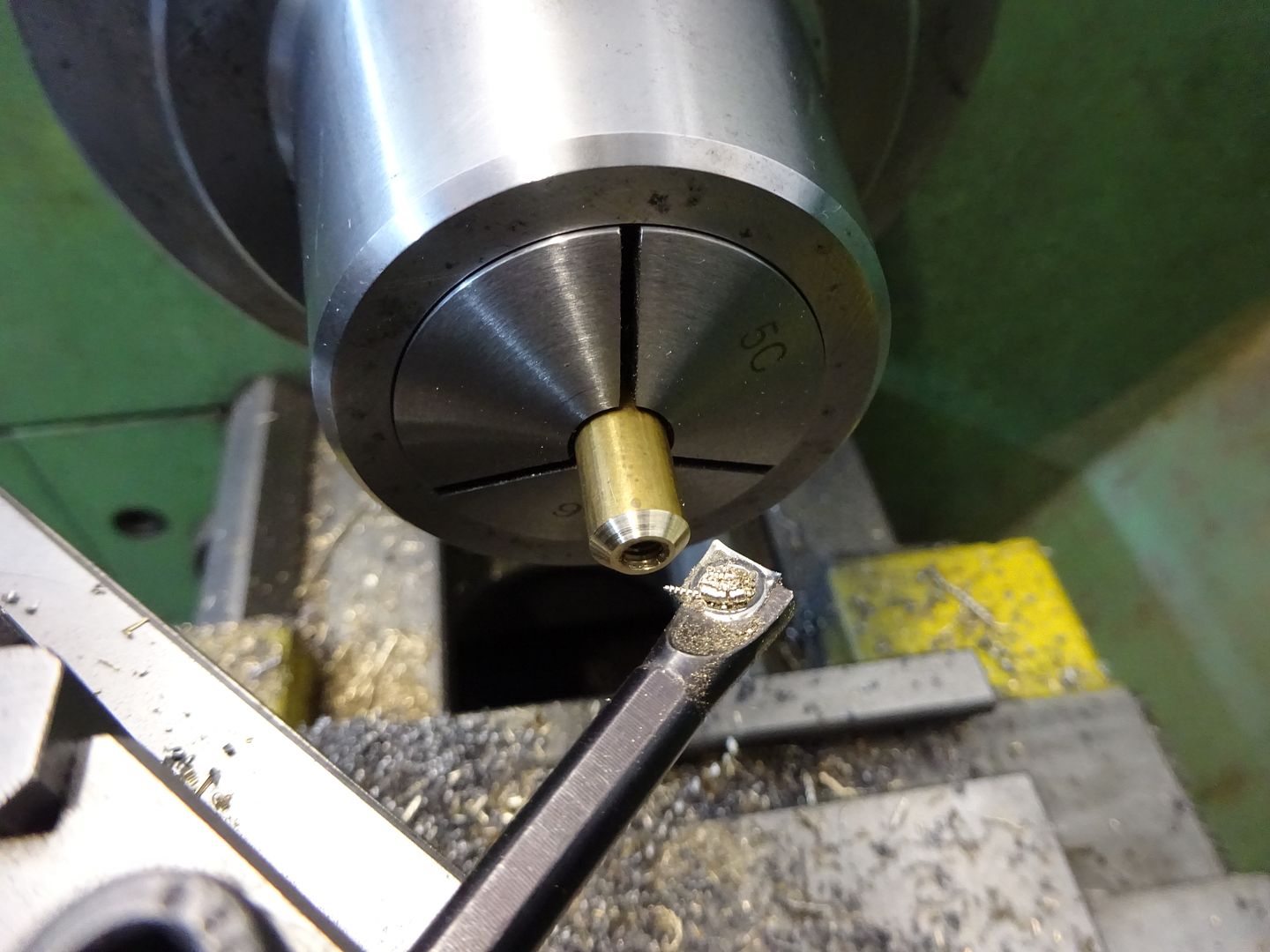
25215 forum posts 3105 photos 1 articles | Oil Cups There are two sizes of oil cup but they can all be made in the same way. Start with a piece of hexagonal brass, face off and then turn and thread the spigot with a metric fine thread. At the same time drill the 1.5mm hole up through the middle then part off. Now take a piece of scrap material and drill and thread so the embrio oil cup can be screwed into it. It worth spending a couple of mins doing a decent job as these holders will come in useful in the future, I have a range of sizes with female thread one end, male the other. With a ball nosed milling cutter enlarge the 1.5mm hole to form the inside of the cup. Now you can either gring up a profile tool from a piece of HSS which can be used to turn down the top of the cup from hex to round and then fed in to create the neck as below. Or just use a round nosed tool the do the waist and use a file to round over the external angle blending the concave waist into the cup main diameter.
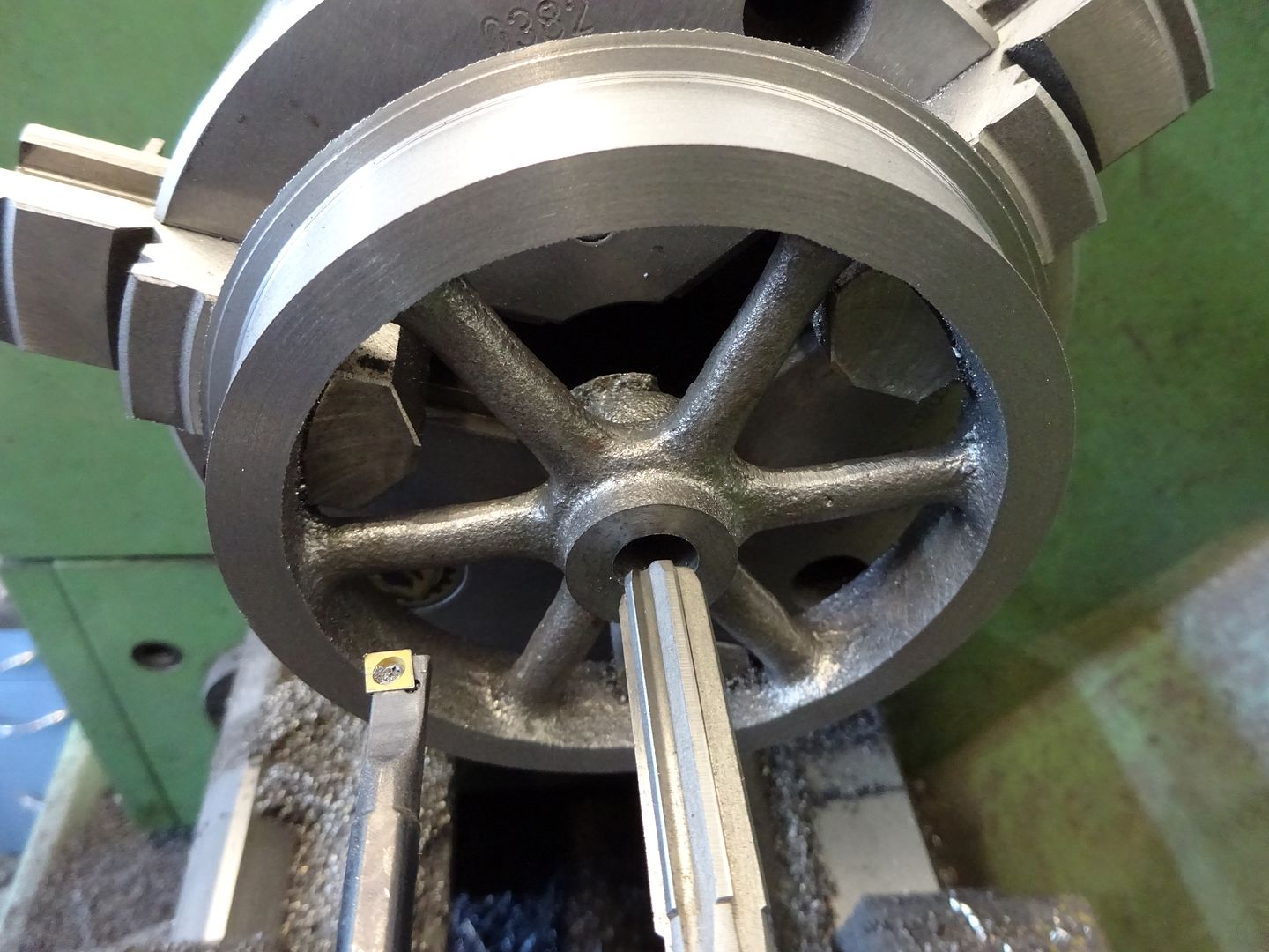
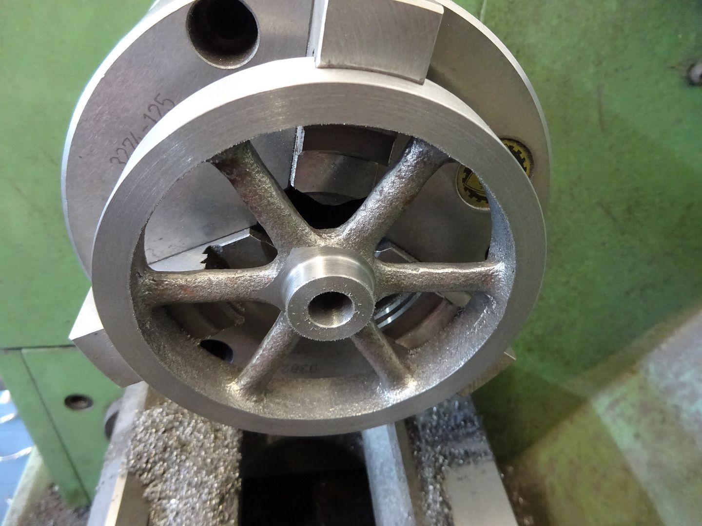
Flywheel Depending where in the world you are located nominal 4" or 100mm flywheel castings sould be available, I went for a couple of "Perseus" ones from Reeves. The castings were quite nice so after a quck clean up with a file I was able to grip them by the inside of the rim using the 3-jaw chuck while the outer face and side were machined. The hub can then be faced, drilled to 9mm, bored to 9.8mm so the 10mm reamer has a true running hole to follow
The flywheel can then be held in the outside jaws while the opposite side of the rim and hub are faced off. I have shown a 18mm wide hub and 15mm wide rim but these are not critical and can be adjusted to suit your castings. The 98mm diameter does matter as much larger and they will be rubbing against the display base!
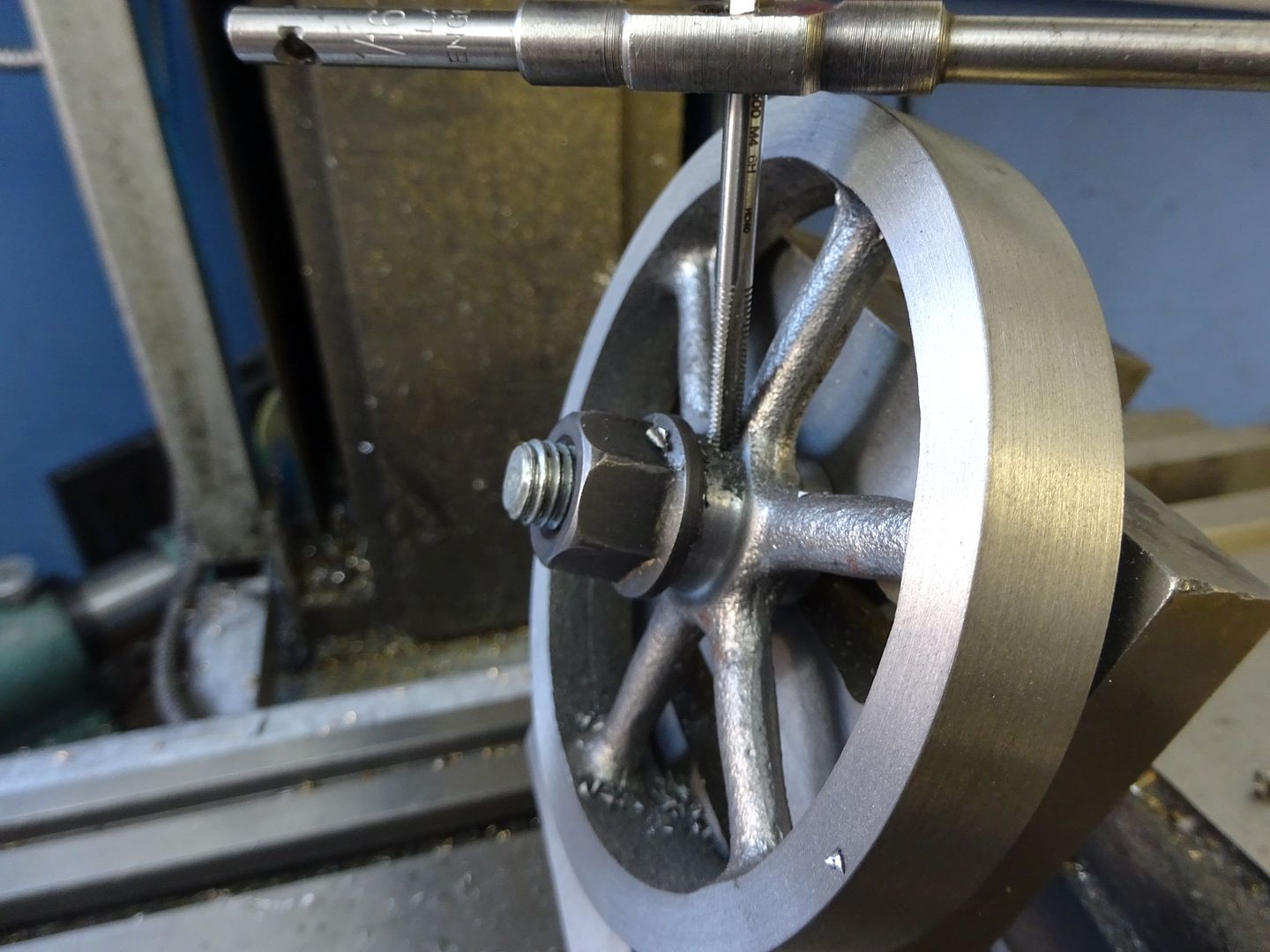
As this is a small engine that won't really do any work I opted to retain the flywheels with a simple M4 grub screw. Hold the flywheel at an angle so your drill and tap just miss the edge of the rim and drill & tap M4. A long reach ctr drill is an advantage to get the hole started. Use a sacrificial bolt through the central hole, start the tap then remove to complete threading.
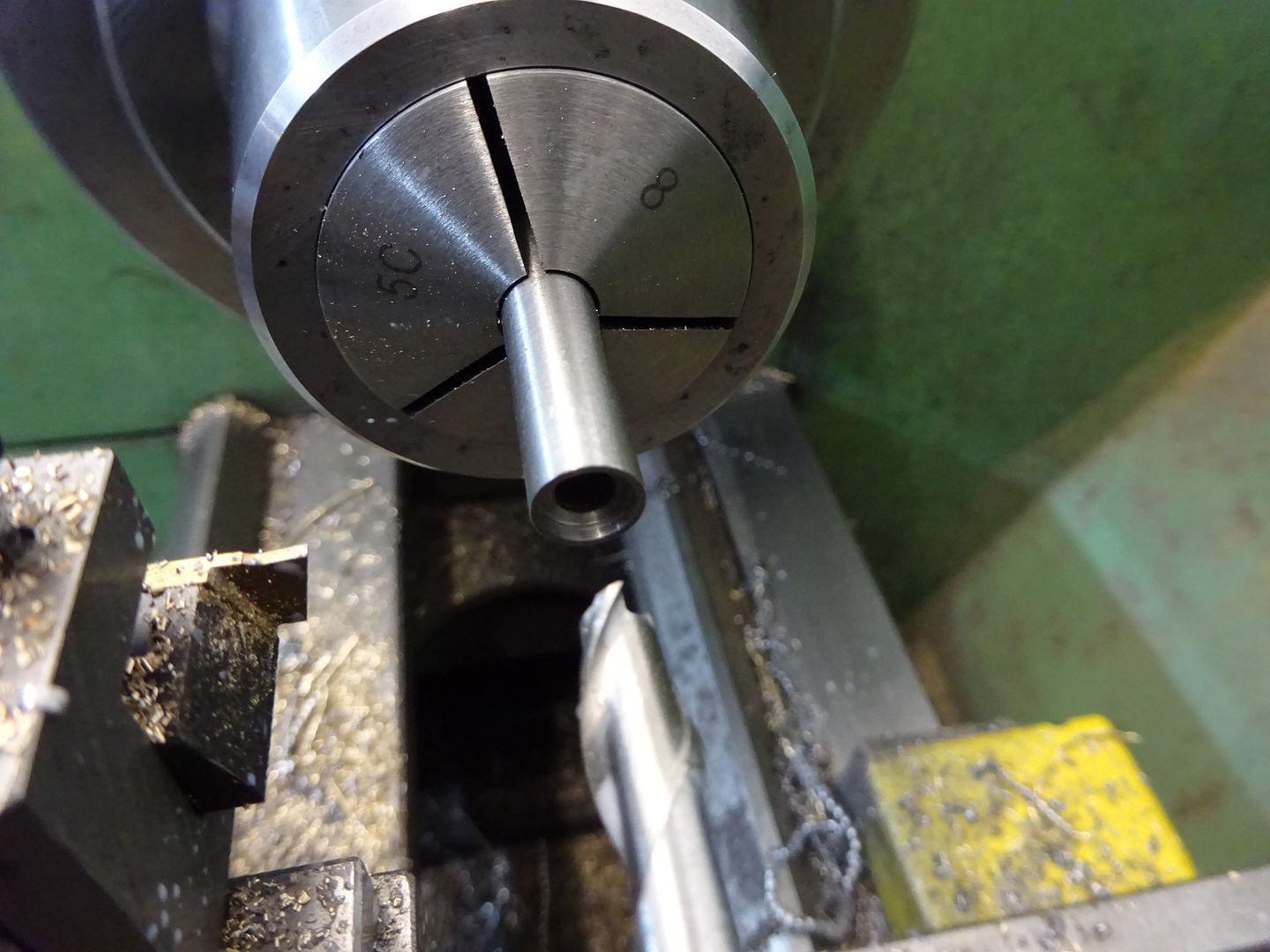
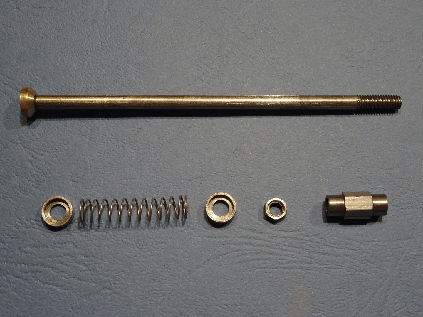
All that remains is to make up a few studs for the various fixings though hex head screws could be used. One thing with metric fasteners is that the standard ones tend to look a bit flat and have a large hex which can look wrong on a period engine. I opted to use the machine turned ones that Bruce (Polly) Engineering sell as these have a smaller hex, are taller and only chamfered heavily on one face. This is what I ended up with.
Oil Cup Drawing to download J Edited By JasonB on 18/04/2016 18:44:06 |
| JasonB | 17/04/2016 19:51:18 |
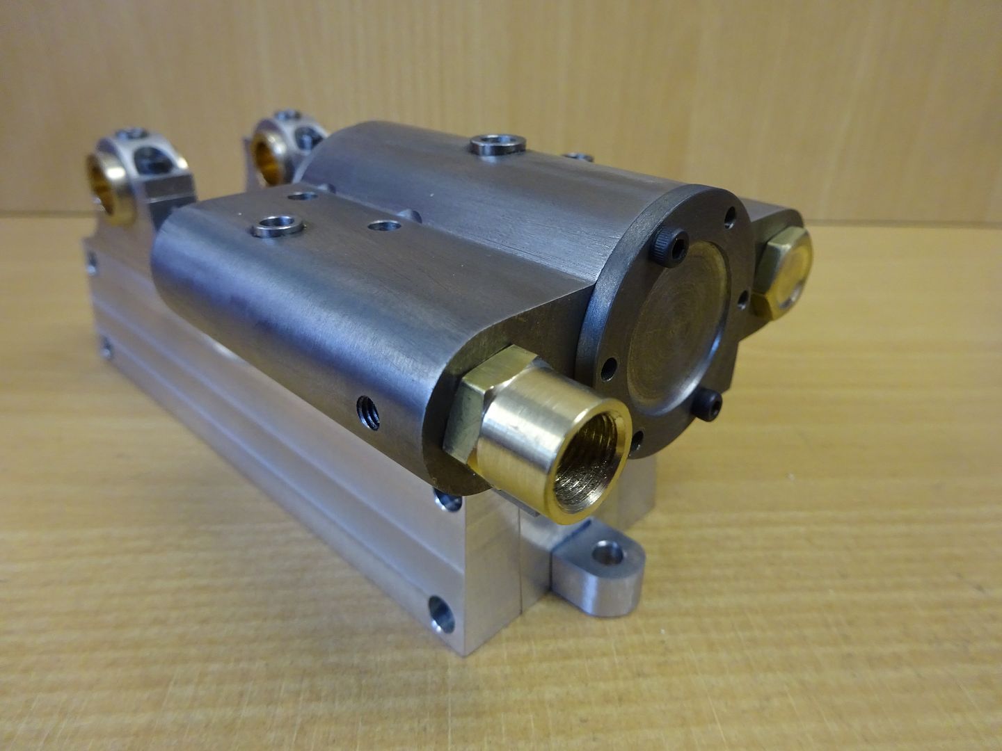
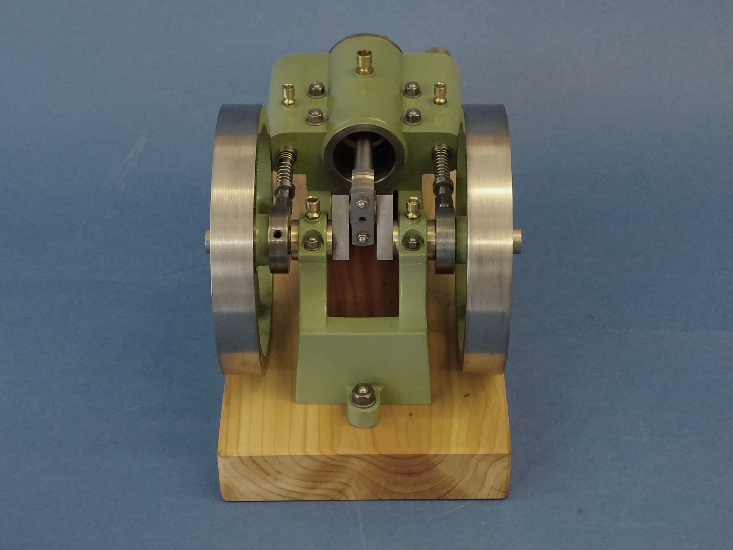
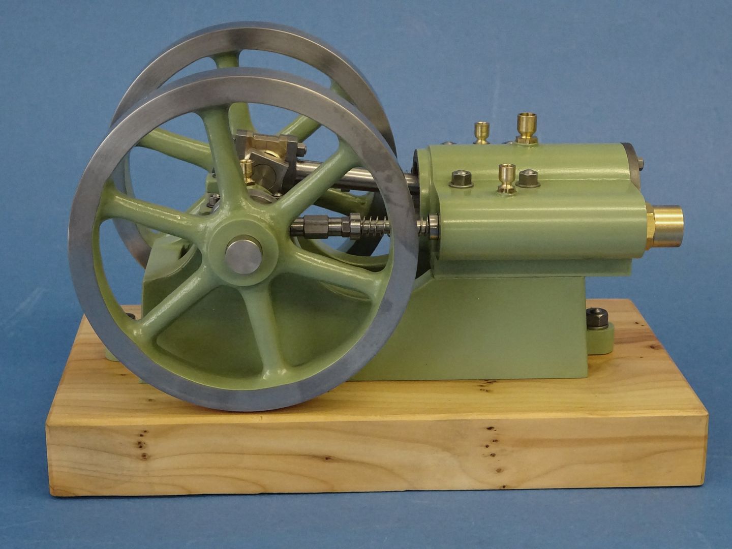
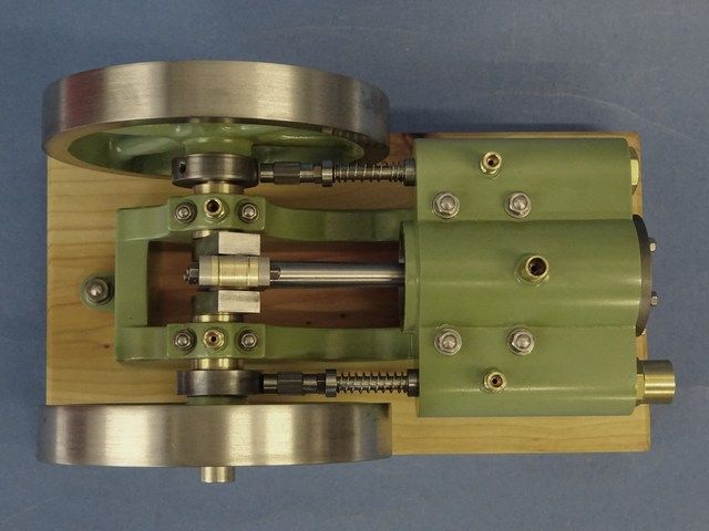
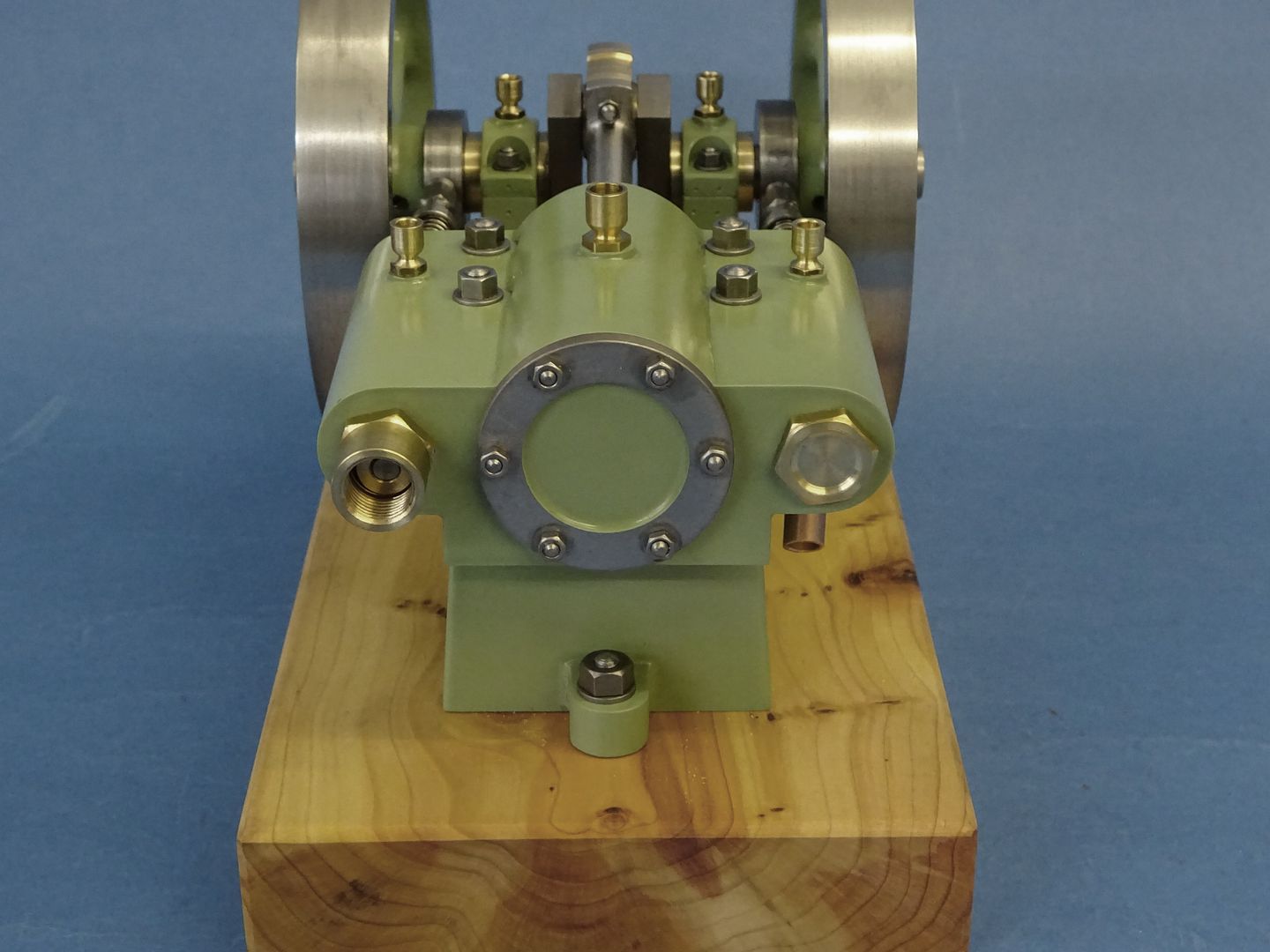
25215 forum posts 3105 photos 1 articles | I like to test run my engines before painting as it saves risking any damage to the paintwork if you have to strip things down to do any alterations. If your fits are OK you should be able to test without any gaskets and just one O ring. As you assemble the engine check that it turns over smoothly after each bit is added as this makes it easier to see where things may be binding. The inlet eccentric should be set so that the inlet is open from TDC until about 5degrees before BDC. The Exhaust should open at BDC and close 5deg Before TDC. Add a drop of oil to the moving parts and connect up some air and see how it goes. If all goes well then the engine can be stripped for painting. Give the parts a wipe over with thinners, prime and then top coat, I used spray cans on this one and settled on Ford "Moss Green" For the base I went with a simple piece of Yew that I had been seasoning for a few years. As you build the engine back up check for smooth running as a bit of stray paint can throw things out. If all is well you should be able to flick the flywheels over like this before the conrod is fitted, the valve springs do slow things down but you should get quite a few turns and a nice gentle stop. The finished engine, not bad for 29day from start to finish working a couple of evenings a week and part of the weekends.
And finally The complete engien running on a couple of psi of air I hope this has been of interest to someone, there is very little feedback on this forum so its hard to know if I'm just posting for the sake of it or if anyone is finding it useful. I would like to thank the couple of members who have PM'd me with a few comments on the drawings which has allowed me to make the odd alteration so they should be Ok if anyone wants to have a go at making one of these engines. The End, Jason |
| Chris Gunn | 17/04/2016 20:18:12 |
| 459 forum posts 28 photos | Jason, thanks for the series, I have downloaded the drawings and intend to make one when I have finished my Stuart Turner Undertype. Chris Gunn |
| Roderick Jenkins | 17/04/2016 21:11:14 |
 2376 forum posts 800 photos | Jason, That's very public spirited of you. Another model to add to the to do list. Many thanks, Rod |
| fishy-steve | 17/04/2016 21:35:37 |
| 122 forum posts 30 photos | Just read the thread from start to finish. Really enjoyed it. Thanks Jason! Steve. |
| Roger Provins 2 | 17/04/2016 21:44:00 |
| 344 forum posts | Thanks very much Jason, excellent! I've downloaded all the drawings and will attempt a build when I cleared my current projects. Roger |
| ian j | 17/04/2016 21:47:53 |
 337 forum posts 371 photos | "so its hard to know if I'm just posting for the sake of it or if anyone is finding it useful"
Jason. You are certainly not wasting your time. I've followed this thread from the start & have been down loading the plans. I intend to build this engine in the near future. I always find your post's interesting and informative.. Ian |
| Martin King 2 | 18/04/2016 06:55:08 |
 1129 forum posts 1 photos | Hi Jason, I totally second the above remarks and thank you very much indeed for this interesting and very informative thread. I am coming along nicely with my attempt at modelling this in 3D using Fusion 360 which is proving to be both challenging and great fun! The step by step format of your thread really makes one want to have a go at this attractive yet not too complicated (I may have to remember I said that latert! ) and I look forward to trying it when I can. Thanks again and best regards, Martin |
| Martin King 2 | 18/04/2016 08:31:24 |
1129 forum posts 1 photos | Out of interest, is there any way to download this entire thread complete with pictures and links into a format like pdf or similar? If so are there any copyright implications. Obviously for private use only. Martin |
| Muzzer | 18/04/2016 10:20:12 |
 2904 forum posts 448 photos | Beautiful work, amazing craftsmanship and attention to detail - and interesting machine. Thanks for posting - I love build threads! Murray |
| JasonB | 18/04/2016 18:57:27 |
25215 forum posts 3105 photos 1 articles | Thanks for all the kind comments and good to know I may have tempted a few of you to have a go. Chris, It would be nice to see what you are upto with your undertype as its not a model that ios often seen. Unless you are keeping that for another article after the Garrett. Martin, again it would be nice to see how your 3D drawings are progressing and also hoe Fusion can render the image. Also thanks for your PM's. I will see what can be done about making a single article. For anyone who has been downloading as the parts have been described I would suggest checking you have the most upto date drawing as there have been some revisions, mostly to make things clearer but there were a couple of small errors on the oiler bosses. The full list of drawings is here on dropbox. Now hurry up and get your versions complete as I have almost finished the drawings for the next engine. This will share the same 24mm bore and will be an Entablature engine as I have some O rings and green paint left over J |
| Chris Gunn | 18/04/2016 20:52:00 |
| 459 forum posts 28 photos | Jason, I will take a few pictures of the Undertype in due course, as I am still working on it. I was lucky enough to win an auction for the drawings and castings on a well known auction site. The cylinders and crankshaft were already machined to a very high standard indeed, so as I have not made it all maybe it is not suitable for publication. It is a nice model I always wanted to make back when I was a lot younger but could not afford the castings. Then it was discontinued so I thought I had missed the boat. The engine goes back to a design by Henry Greenly, and was revisited by H A Taylor who did a series in the Model Engineer starting in March 1971. The design was then taken up by Stuart Turner who produced the castings, but I am not sure when the engine was dropped from the range. It is a change from the 4CD for sure, while I decide whether to make another traction engine. Chris Gunn
|
| Muzzer | 18/04/2016 22:01:24 |
2904 forum posts 448 photos | What CAD did you use? 3D PDF looks good. Murray |
| JasonB | 19/04/2016 07:04:35 |
25215 forum posts 3105 photos 1 articles | Alibre PE which is now sold as Cubify Design. |
| Muzzer | 19/04/2016 08:26:00 |
2904 forum posts 448 photos | Aha. I used to have Alibre Free, then trialed Geomagic when I lost it - similar difference. Nice app. |
| Martin King 2 | 12/05/2016 09:09:34 |
1129 forum posts 1 photos | Hi Jason, Been a bit busy but still trying with Fusion 360. Here is a pic of the base assembly and my first ever play with a render, excuse the bright colours, got carried away with the materials list!
Still finding areas of this program exasperating but fun! Trying to import the cap screws from Mcmaster Carr and duplicating them is less than intuitive and the hierarchical (?) system for components has to be just right or all sorts of problems arise. However that said I am a total novice at this and the power of this program leaves me amazed constantly. Wjhen I get my new bandsaw i have the ally billet standing by to make a start on this from yours (& mine??) drawings Regards, Martin |
| Chris Gunn | 07/06/2016 11:14:15 |
| 459 forum posts 28 photos | Jason, as said earlier I was inspired to make a start and had a rummage around and found 2 round cast test pieces about 5" diameter I scrounged from a foundry years ago, and parted off a slice and then thought I would do 1 for each of my grandkids, 4 in all, so parted off 3 more slices. I have made everything except the con rod and piston and the flywheels since the beginning of May for 4 engines all from the come in handy box. I have just bought the Perseus flywheels from Reeves, I had to get 10 to get a discount, so I have 2 spare Perseus flywheels. If anyone wants these PM me, first come first served. I will take some pics at a later date. Chris Gunn |


Please login to post a reply.
Magazine Locator
Want the latest issue of Model Engineer or Model Engineers' Workshop? Use our magazine locator links to find your nearest stockist!
Sign up to our Newsletter
Sign up to our newsletter and get a free digital issue.
You can unsubscribe at anytime. View our privacy policy at www.mortons.co.uk/privacy
Latest Forum Posts
- *Oct 2023: FORUM MIGRATION TIMELINE*
05/10/2023 07:57:11 - Making ER11 collet chuck
05/10/2023 07:56:24 - What did you do today? 2023
05/10/2023 07:25:01 - Orrery
05/10/2023 06:00:41 - Wera hand-tools
05/10/2023 05:47:07 - New member
05/10/2023 04:40:11 - Problems with external pot on at1 vfd
05/10/2023 00:06:32 - Drain plug
04/10/2023 23:36:17 - digi phase converter for 10 machines.....
04/10/2023 23:13:48 - Winter Storage Of Locomotives
04/10/2023 21:02:11 - More Latest Posts...
- View All Topics
Support Our Partners


Shopping Partners
Subscription Offer

Latest "For Sale" Ads
- Reeves** - Rebuilt Royal Scot by Martin Evans
by John Broughton
£300.00 - BRITANNIA 5" GAUGE James Perrier
by Jon Seabright 1
£2,500.00 - Drill Grinder - for restoration
by Nigel Graham 2
£0.00 - WARCO WM18 MILLING MACHINE
by Alex Chudley
£1,200.00 - MYFORD SUPER 7 LATHE
by Alex Chudley
£2,000.00 - More "For Sale" Ads...
Latest "Wanted" Ads
- D1-3 backplate
by Michael Horley
Price Not Specified - fixed steady for a Colchester bantam mark1 800
by George Jervis
Price Not Specified - lbsc pansy
by JACK SIDEBOTHAM
Price Not Specified - Pratt Burnerd multifit chuck key.
by Tim Riome
Price Not Specified - BANDSAW BLADE WELDER
by HUGH
Price Not Specified - More "Wanted" Ads...
Get In Touch!
Do you want to contact the Model Engineer and Model Engineers' Workshop team?
You can contact us by phone, mail or email about the magazines including becoming a contributor, submitting reader's letters or making queries about articles. You can also get in touch about this website, advertising or other general issues.
Click THIS LINK for full contact details.
For subscription issues please see THIS LINK.
Digital Back Issues


Donate

 Register
 Log-in
Model Engineer Magazine
- Percival Marshall
- M.E. History
- LittleLEC
- M.E. Clock

ME Workshop
- An Adcock
- & Shipley
- Horizontal
- Mill

Subscribe Now
- Great savings
- Delivered to your door

Pre-order your copy!
- Delivered to your doorstep!
- Free UK delivery!
All Forum Topics > Work In Progress and completed items > Jowitt MkII Popett Valve Engine Build