Forum sponsored by:

Further Adventures with the Sieg KX3 & KX1
A thread for new owners of these machines to post in.
| Ron Laden | 27/07/2022 04:02:57 |
 2320 forum posts 452 photos | Thats also impressive Jason, 3 hours per side I was thinking it would have been much longer. How do the cutters fare are they still good after 6 hours I was thinking thats quite a lot of work but for a quality tool maybe not. Do you tend to use carbide more than HSS or is it a mix depending on the job. |
| JasonB | 27/07/2022 06:58:29 |
 25215 forum posts 3105 photos 1 articles | Cutters had done quite a lot of work before this and will do quite a bit more. All carbide for the milling cutters on the CNC for me the main reason being that it would slow the job down a lot if I went with HSS with the bonus that the carbide stays sharper for longer |
| JasonB | 04/08/2022 18:50:16 |
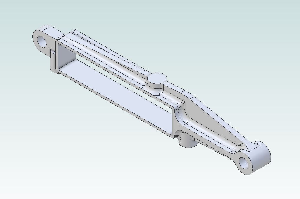
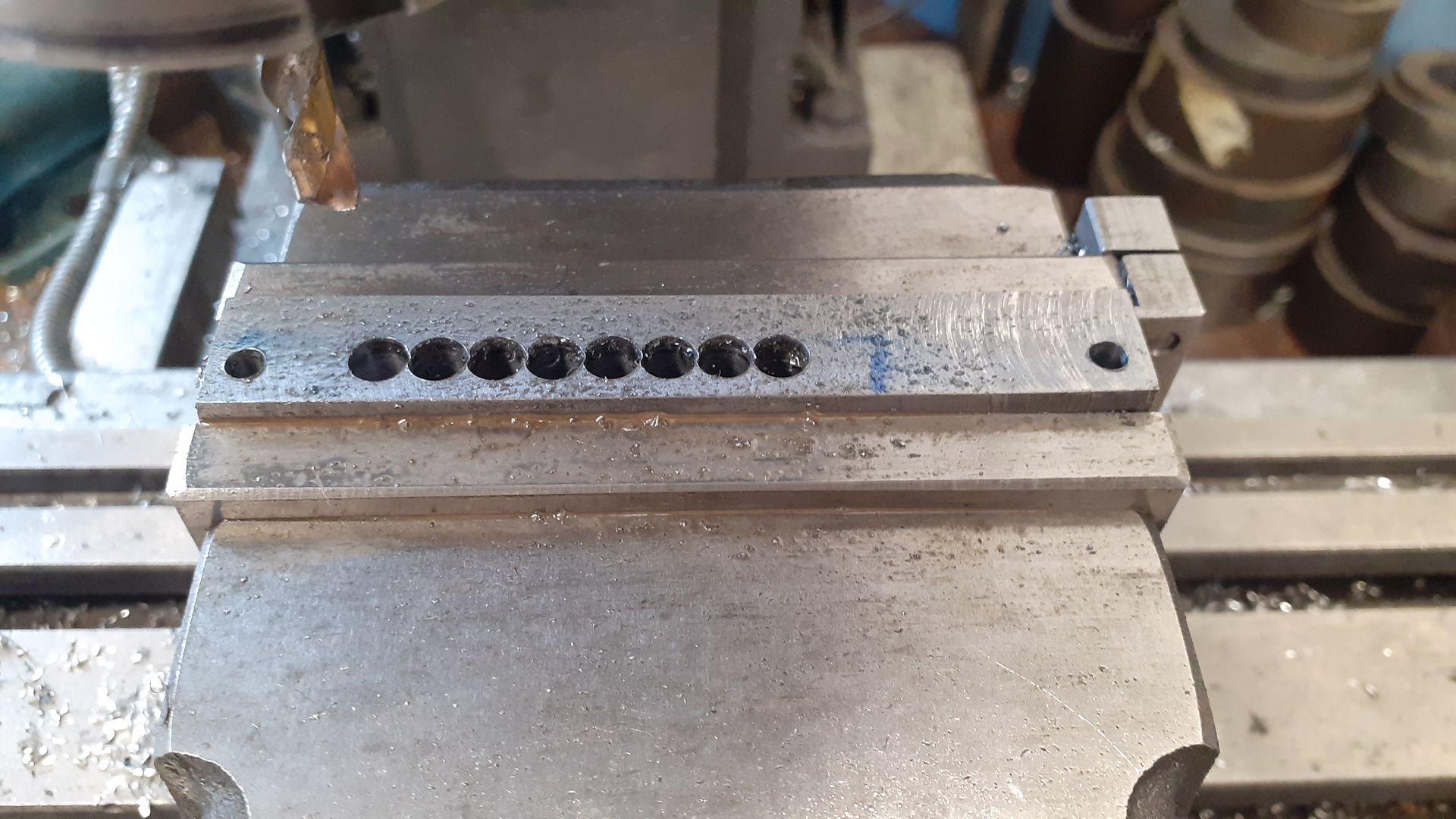
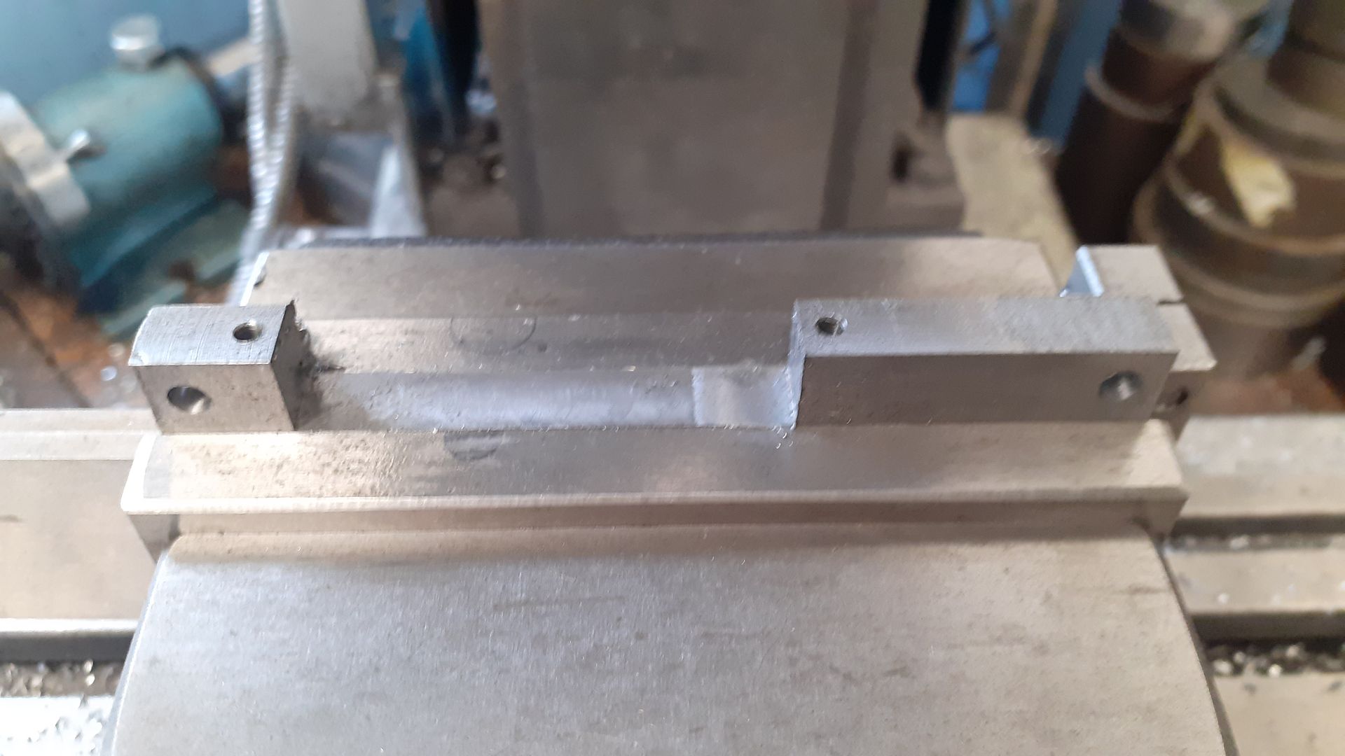
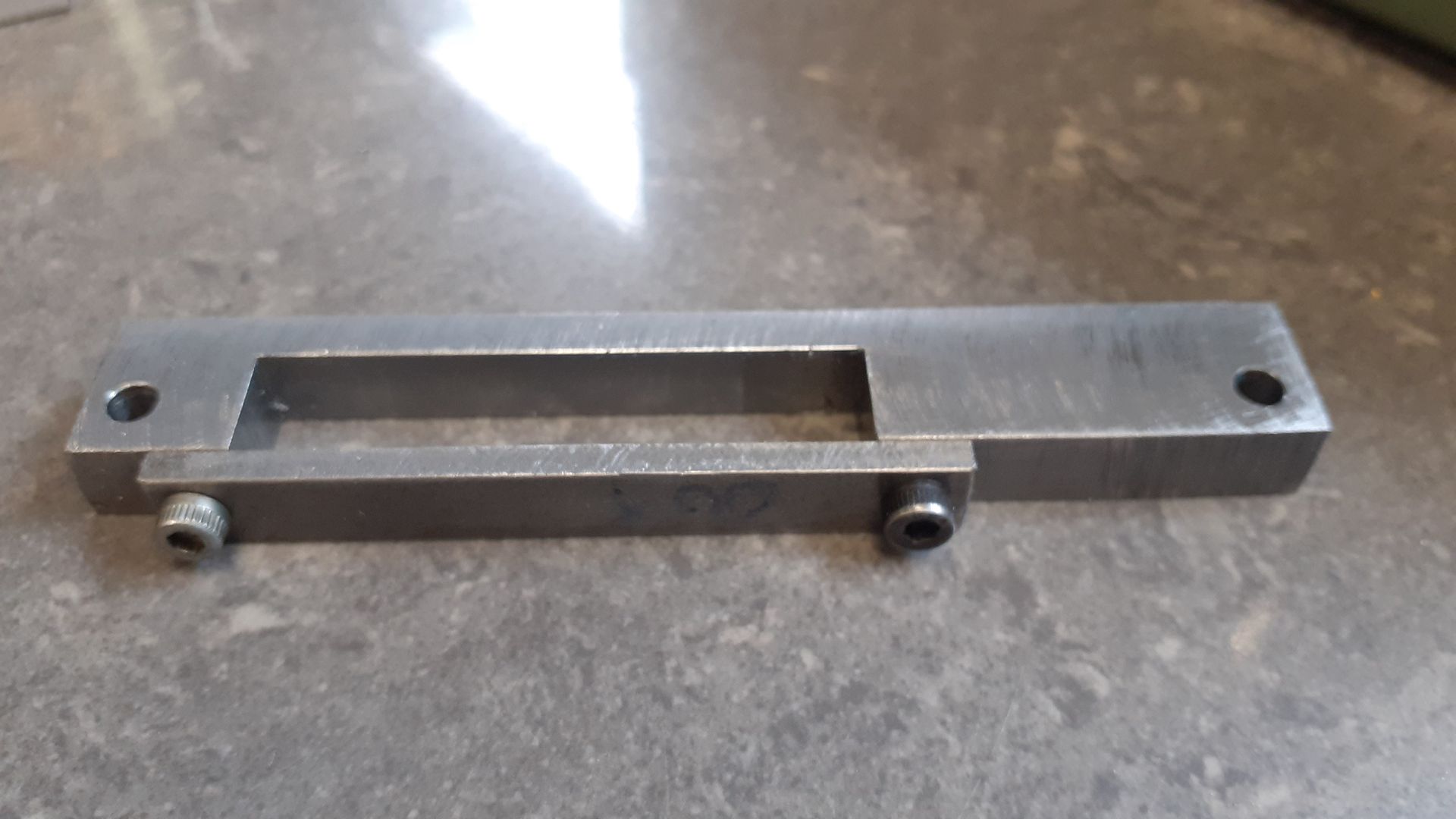
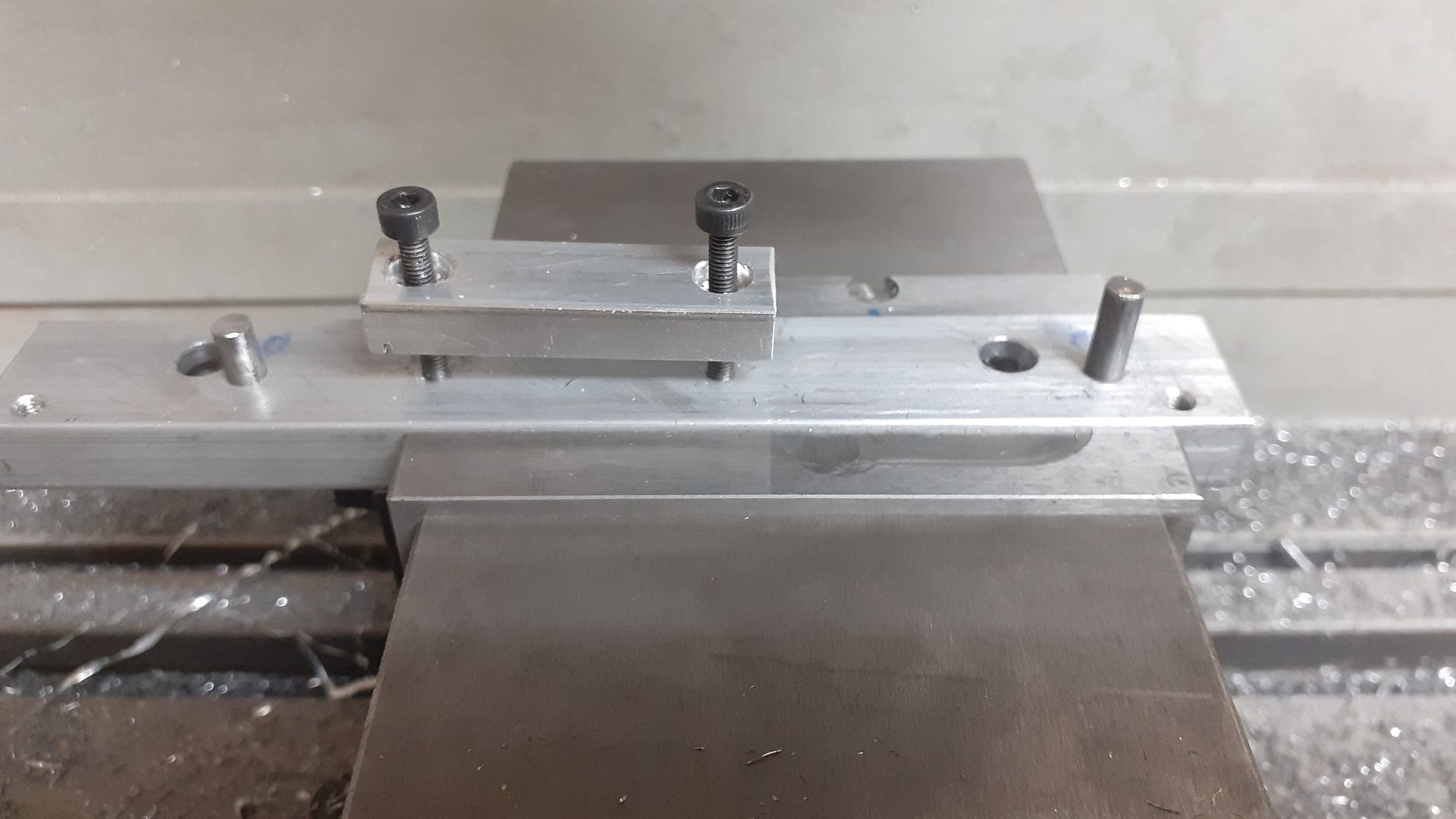
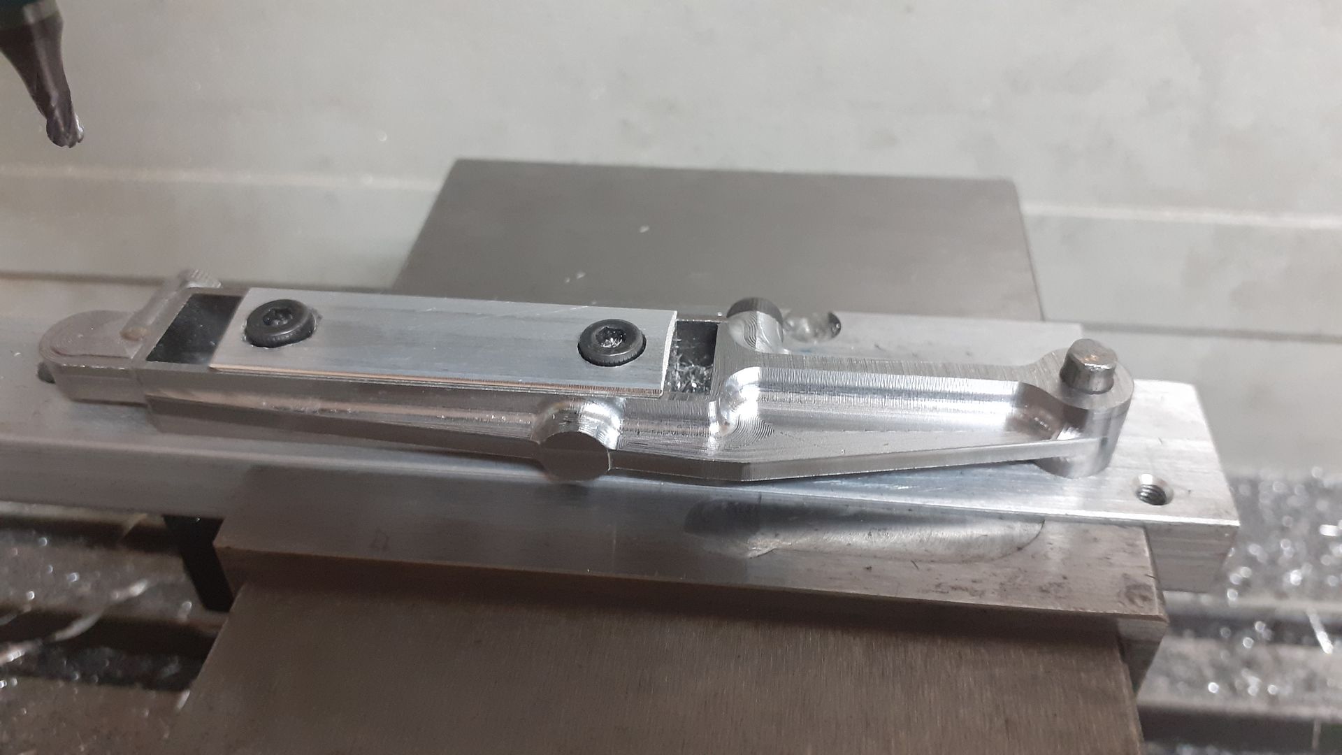
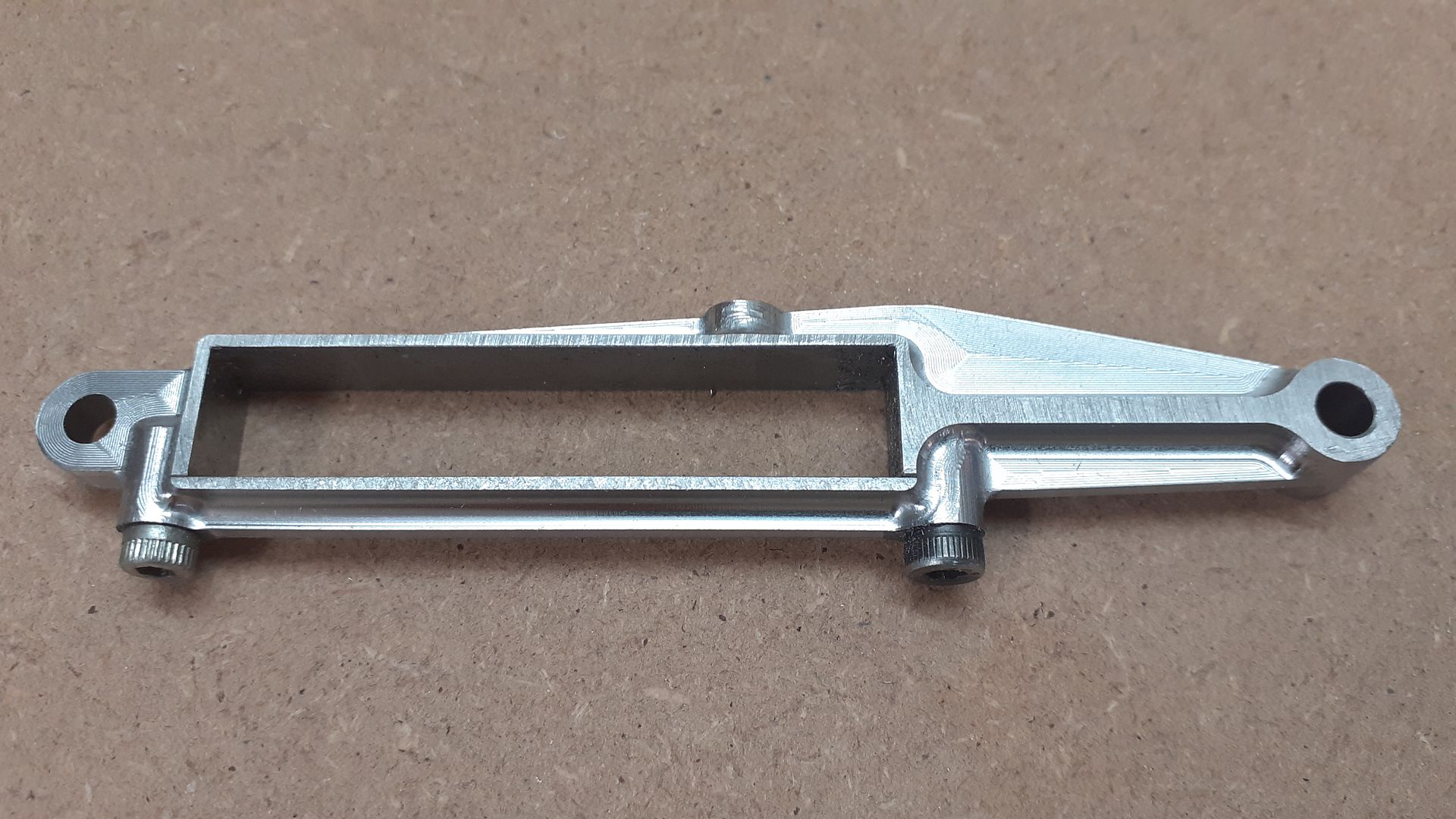
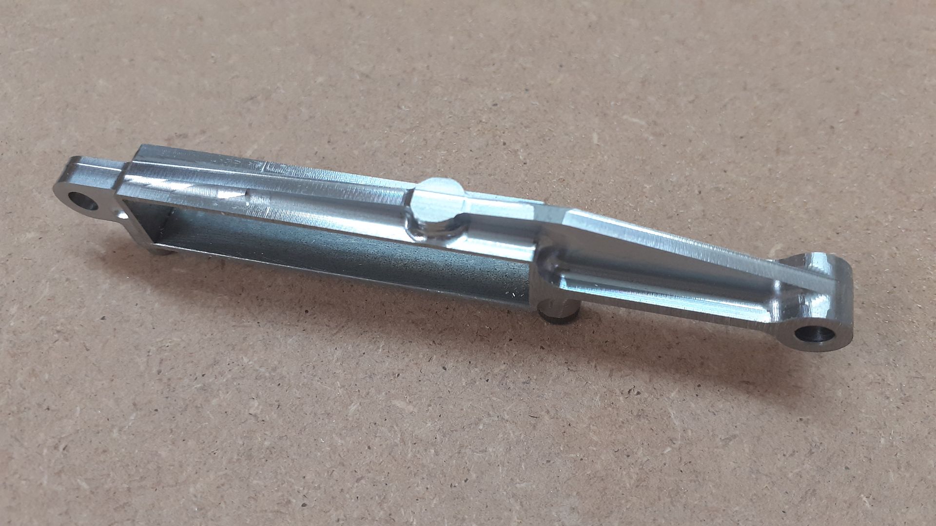
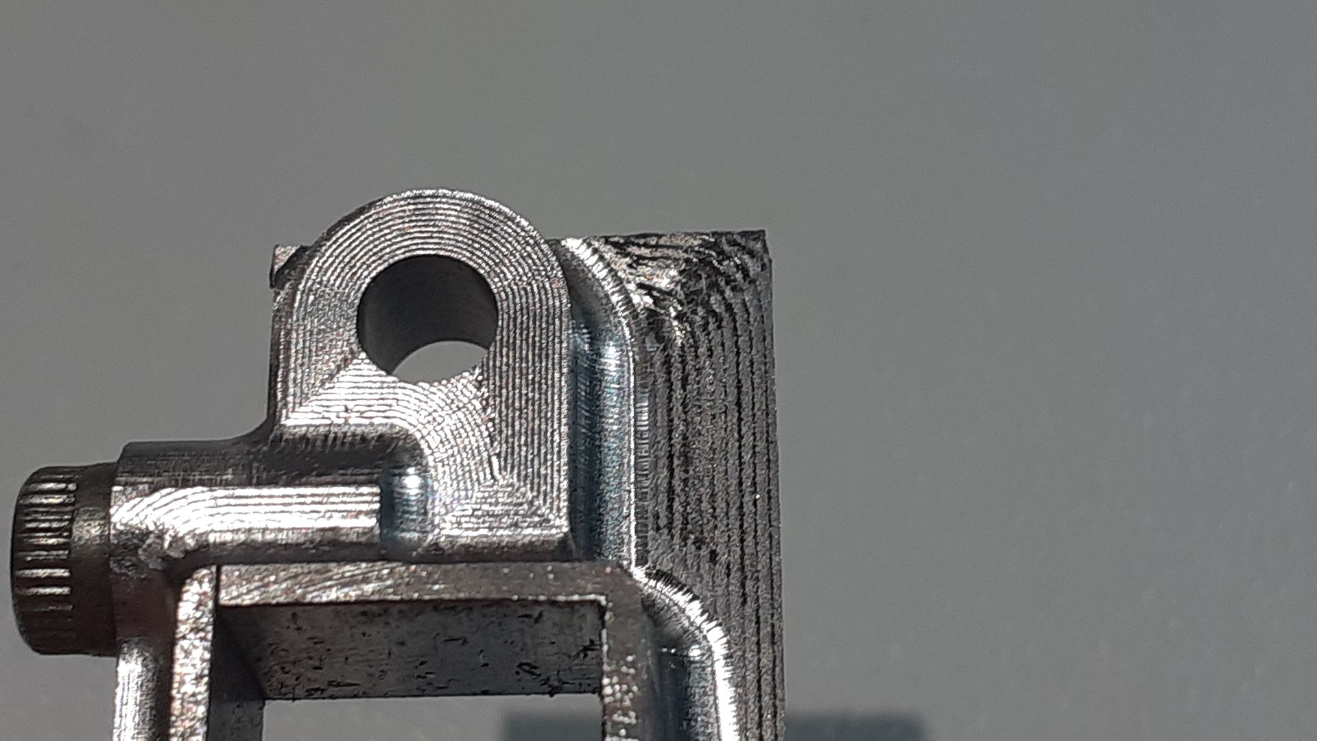
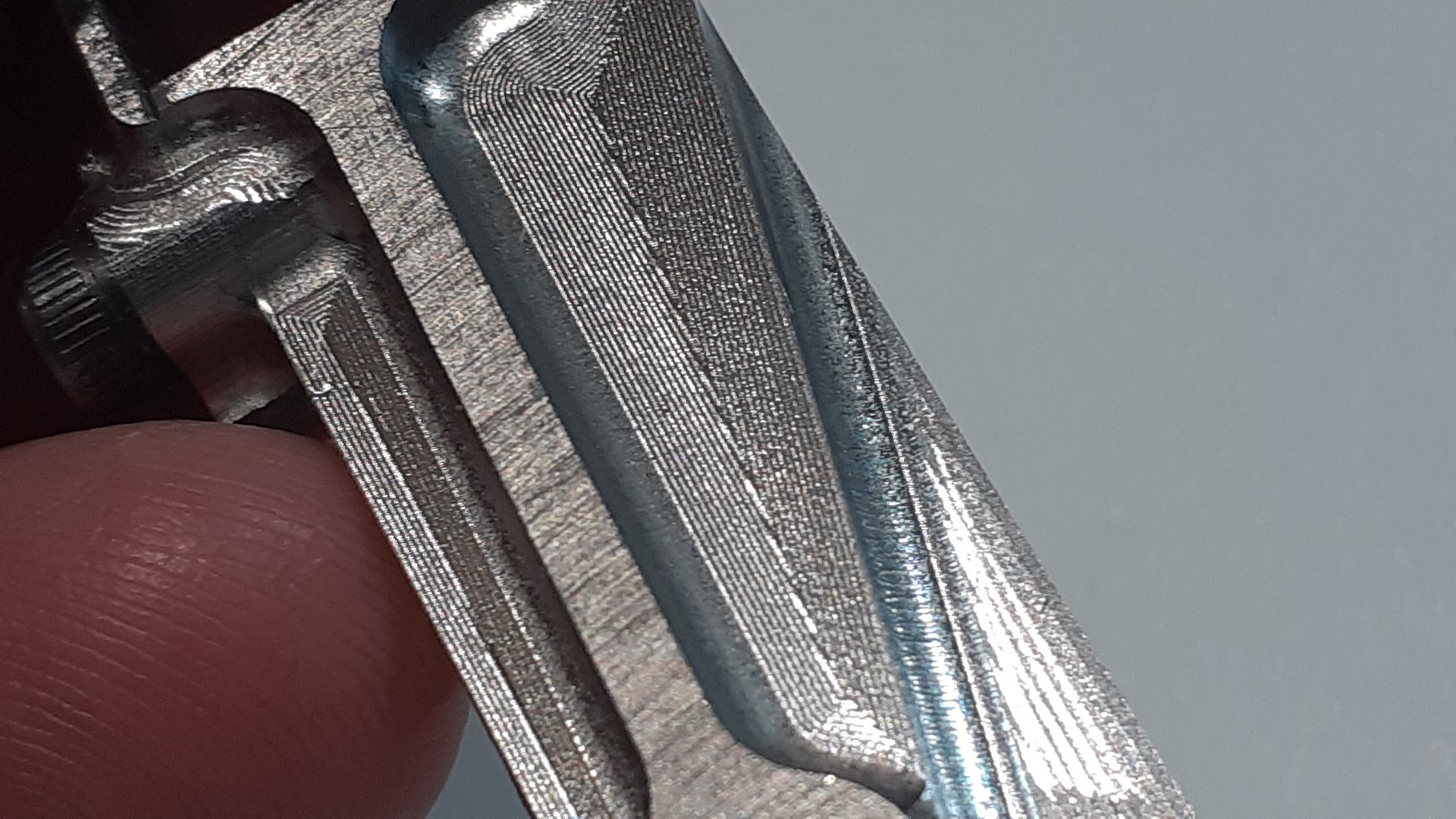
25215 forum posts 3105 photos 1 articles | The little Otto flame sucker that I'm working on has a form of scotch yoke that is pivoted at one end and connects to the conrod big end at the other. I had sent Graham Corry a basic sketch of this with the critical sizes from which he made a pattern and had some cast in brass with the intention to have the crank run against the brass slot. Having subsequently seem images of Tom's larger size replica I decided to go down that route which has split bearings for the crankshaft and to get them into place the bottom of the Yoke is a separate part. |
| Ron Laden | 07/08/2022 05:34:06 |
2320 forum posts 452 photos | I know its CNC Jason but the parts you produce with it are seriously impressive and never cease to amaze me. Ron |
| Ian Johnson 1 | 07/08/2022 09:25:37 |
| 381 forum posts 102 photos | Very impressive results Jason, never be able to tell the difference between a casting when painted IanJ |
| JasonB | 20/03/2023 16:20:37 |
25215 forum posts 3105 photos 1 articles | Well it's been a while but a couple of castings from the patterns shown on the previous page arrived today. Look to be quite good with little flash and the two halves seem to line up well. hopefully they will have soft centres.
|
| JasonB | 11/05/2023 12:24:51 |
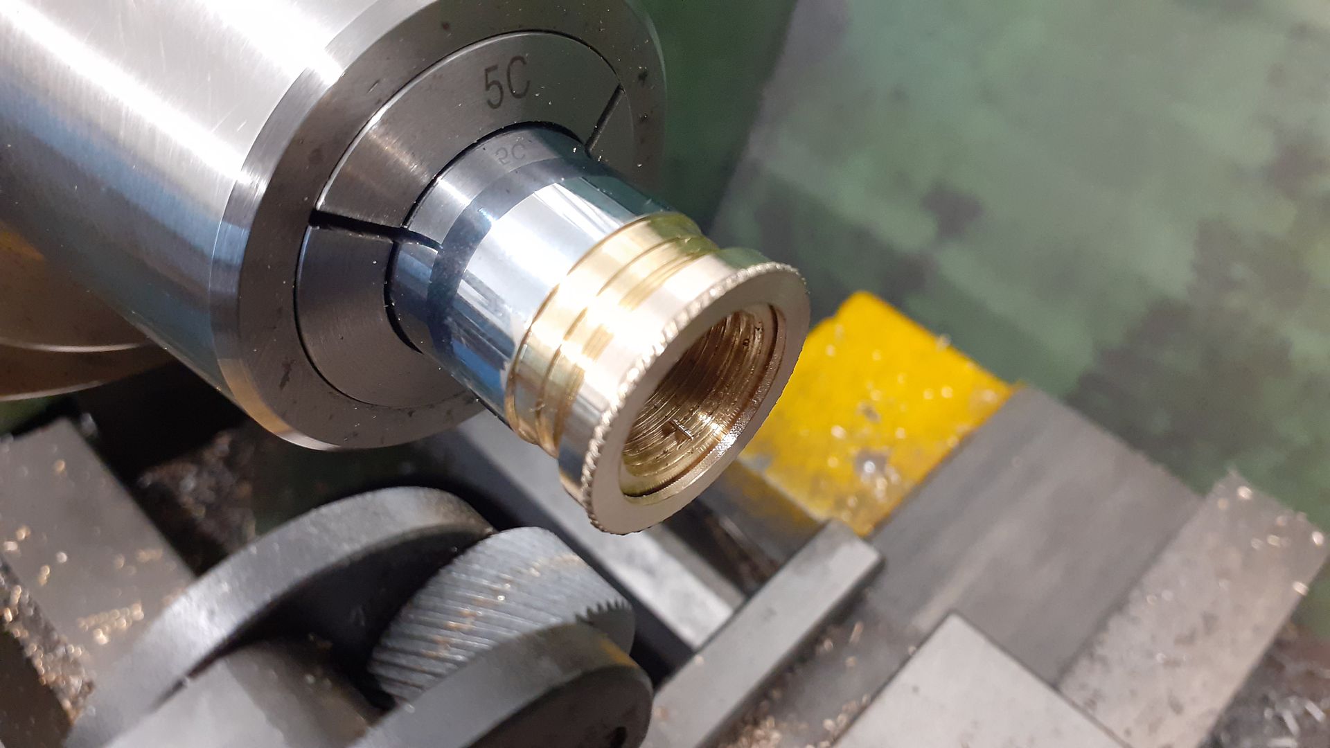
25215 forum posts 3105 photos 1 articles | I've been wanting to try thread milling for a while and the need finally came up so time for a new adventure. The part in question is a gland nut that fits onto the end of a steam engine cylinder to seal the piston rather than it having piston rings. The lower lip just needs to clear the 19mm dia piston and the thread I chose was M22 x 0.5mm and needs to go as close as possible to the lip.
I made use of a bar end of 1" brass and milled the top flat enough using the jog function as a glorified power feed control and then use the CAM in F360 to produce the code to firstly rough out the two bores leaving 0.3mm of material which was then taken to finished size in to passes of 0.2 and then 0.3mm. A change of tool to a single tooth,5 flute thread mill took care of the thread, I ha dread of possible tool deflection so took light 0.1mm steps and a spring pass. Quite happy with how it came out so will be using it again particularly as one cutter can do several pitches and almost unlimited diameters
Edited By JasonB on 11/05/2023 12:25:24 |
| John Haine | 11/05/2023 13:31:29 |
| 5563 forum posts 322 photos | Jason, thread milling is cool! I have use two tools, one a modified M8x1 tap, the other a standard small insert tip inside threading tool I got from JB a few years back. Conveniently that has a cylindrical shank with a flat and takes the insert with the cutting edge exactly on axis. The one made from a tap has to be used in conventional milling mode but the other was quite happy climb milling from the bottom of the bore. I cut an M14x1mm thread in one pass to fit the Unimat spindle and the fit was perfect. |
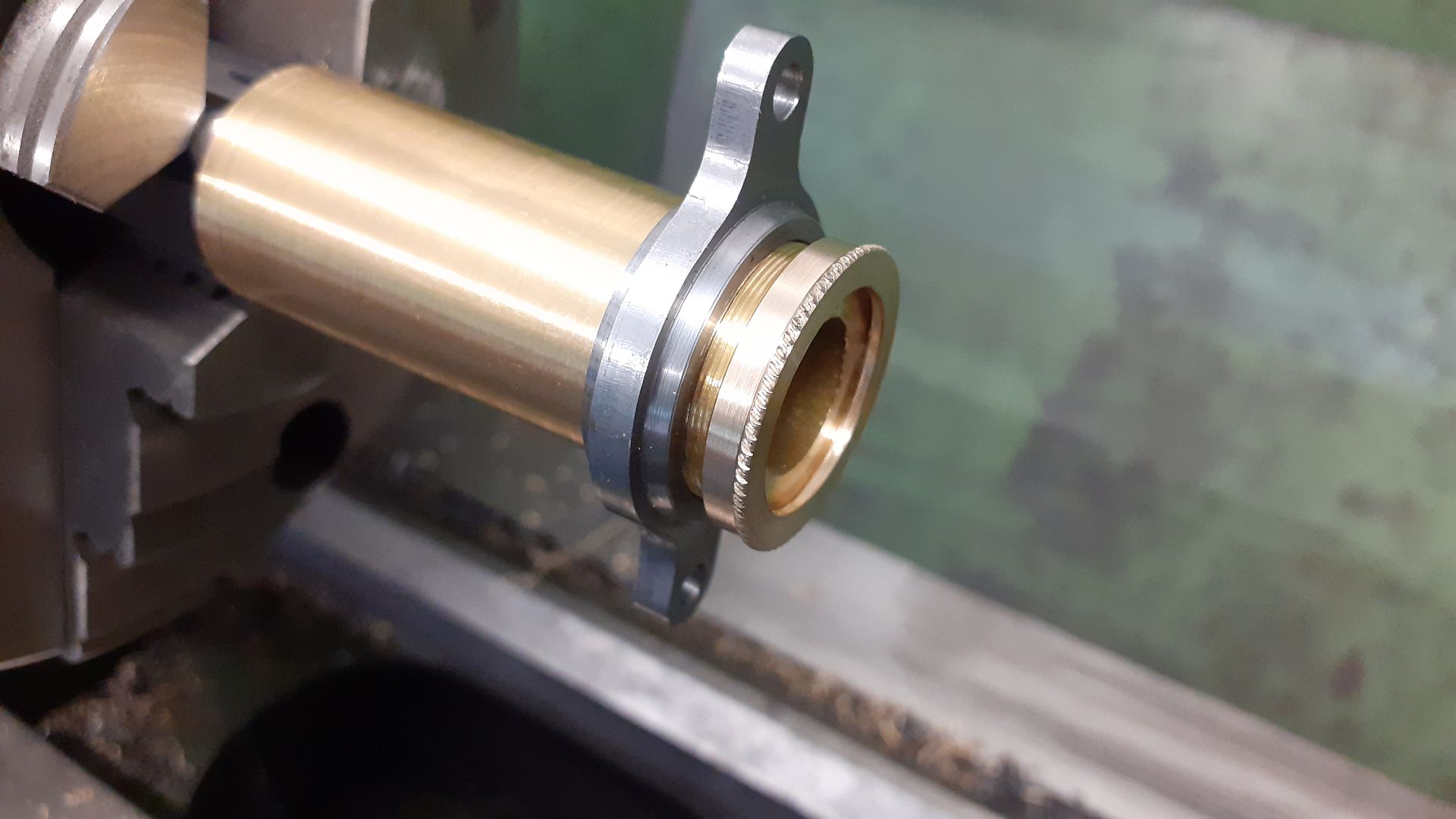
| JasonB | 12/05/2023 18:44:31 |
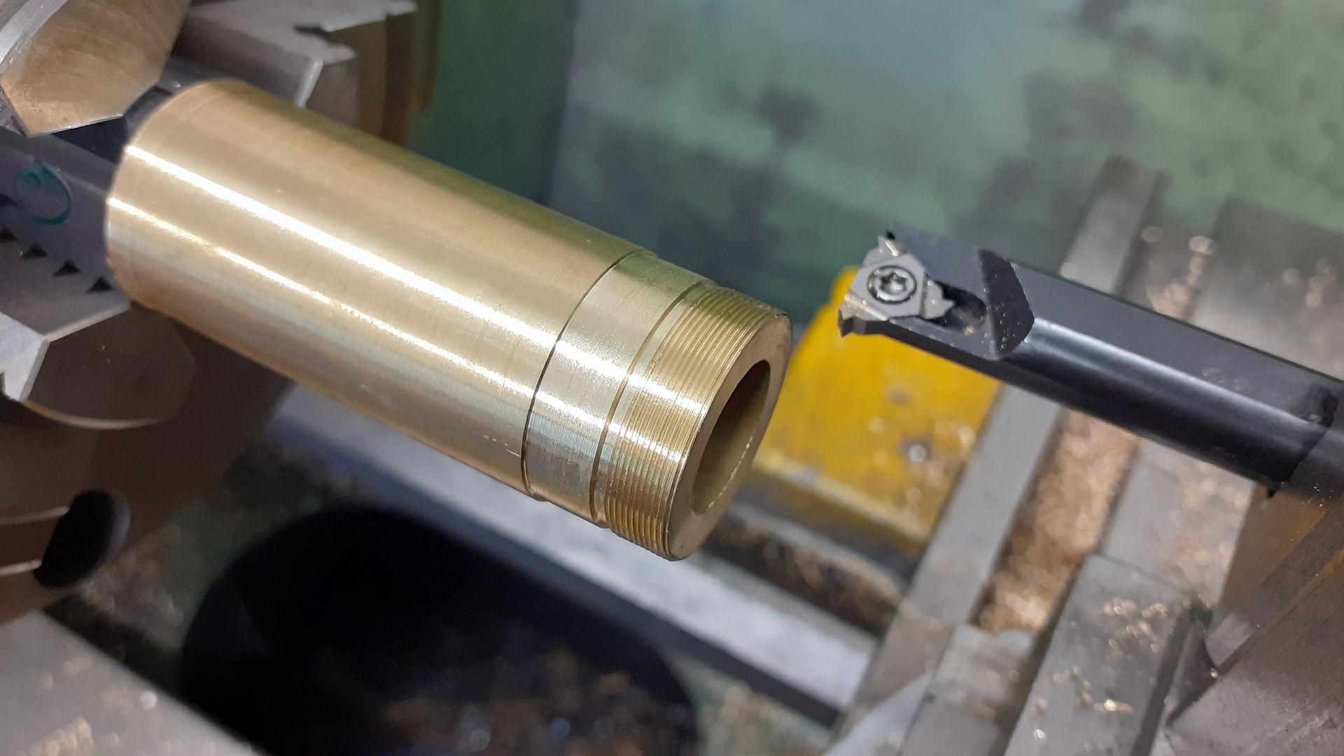
25215 forum posts 3105 photos 1 articles | Thanks John, a couple of others have said they use reground "normal" taps which I'll bear in mind. The female thread was only half the part and I really needed the male to make sure it all went together so I threaded a short length of bar with a test thread on the lathe and it screwed on very nicely. I made use of that test thread to hold the part while the remaining turning was done. Using one wheel only of teh diamond knurl gives a reasonable looking "rope" knurl
Edit, looks like the forums reduction of image size make sit a bit hard to see the 0,5mm pitch thread so here is another shot, click to get it even bigger
Edited By JasonB on 12/05/2023 18:48:26 |
| Nealeb | 13/05/2023 08:51:11 |
| 231 forum posts | I like the idea of thread milling but put off by the cost of cutters! The idea of a modified tap sounds interesting but how is it modified? My understanding of a thread mill is that it is "flat", and even a multi-tooth cutter (to get proper thread crest rounding) looks like a set of circular cutters stacked. A tap, of course, has a helical thread. Do you grind off almost everything to leave the equivalent of a single-tooth cutter? Itching to have a go now... (Shouldn't say multi-tooth, I realise, but I mean a cutter which cuts several adjacent threads at the same time. I see these listed in the catalogues) Edited By Nealeb on 13/05/2023 08:53:06 |
| JasonB | 13/05/2023 10:03:35 |
25215 forum posts 3105 photos 1 articles | Yes you grind off everything except one cutting edge soo feed rate is a bit slower than the one I use das that has 5 cutting edges. You can also get the "single tooth" style in full form so don't have to us the multi tooth ones. |
| Emgee | 13/05/2023 11:45:08 |
| 2610 forum posts 312 photos | Jason I think those single point cutters are only suitable for a dedicated pitch but can do fine or coarse thread and as you say any diameter. Info below from the linked page, These thread mills are suitable for machining internal metric coarse and fine threads with the same pitch using the same cutter. Emgee
|
| Martin Connelly | 13/05/2023 12:58:33 |
 2549 forum posts 235 photos | I found somewhere a figure for the minimum diameter of the thread being cut compared to the diameter of the cutting tool for straight threading tools with no helix angle. I think the tool had to be 60% of the thread diameter to ensure the thread was not overcut due to the tool helix angle (0° ) being different to the thread helix, the thread helix angle reducing as diameter increased. This means that if, for example, you wanted to make a 1mm pitch thread from a Ø6mm thread milling cutter the thread being produced would have to be 10mm diameter at least. A play with 3D CAD would confirm if this is the correct percentage. For purchased single pitch cutters I think the manufacturers will have a data sheet stating the limits of what can be done with each tool. I have also used a manufacturer's web site (Vargus) to create G code for one of their cutters, put in your parameters and it will either say no way or produce G code. When you make a tool from a tap there is the added problem that the tap is at a fixed helix angle and the material behind the cutting edge is not necessarily going to have the same back clearance as a tool manufactured for the job. You would have to remove a fair amount of material from behind the cutting edge to ensure there was sufficient clearance or only use it on quite large diameters to ensure there was no rubbing or overcutting of the thread. Once again 3D CAD could be used to check for interference. Martin C Smiley removed Edited By Martin Connelly on 13/05/2023 12:59:03 |
| JasonB | 13/05/2023 13:27:08 |
25215 forum posts 3105 photos 1 articles | Emgee, yes the full form ones will only suit a particular pitch as they have the correct radius for that given pitch exactly the same as full form threading inserts used on a lathe. I was using a partial form so able to do any pitch within the range again like partial form threading inserts this is what I used which will do 0.5 to 1.0mm pitch and anything in between, you need to make a slight allowance for the more pointed profile of the cutter when doing the larger pitch. |
| John Haine | 15/05/2023 07:31:59 |
| 5563 forum posts 322 photos | Somewhere on this forum there's a thread where the use of taps for thread milling was discussed with several contributions from John Stevenson, though I can't readily find it. I did contribute myself and John was very helpful. For my M14x1 internal thread I use two cutters (different trials). One was an M8x1 tap, with all the rows of teeth ground away except one and the tip ground square. That worked well but is limited to conventional milling down into the hole, and unless you also grind away all the teeth but one it will only do one pitch. A single point cutter (like my internal threading lathe tool I discussed) can start at the bottom of the hole and spiral out, climb milling all the way which is quieter and gives a better finish. To generate the code I used a little program provided by Chestnut Pens which Richard kindly modified to allow the use of a tap. |
| JasonB | 15/05/2023 07:45:04 |
25215 forum posts 3105 photos 1 articles | was this it ? |
| John Haine | 15/05/2023 09:51:11 |
| 5563 forum posts 322 photos | Aha! Thanks Jason, well found. From one of my earlier posts in that thread: After some though I decided that the helix angle of the tap isn't really a problem. You have to remember that the tap is significantly smaller than the hole you are threading. Yes, in principle as the tap rotates the helix may cause some rubbing, but both the smaller tap radius and its form relief are quickly taking the cutter surface away from the work, as it were. Edited By John Haine on 15/05/2023 09:51:56 |
| JasonB | 03/10/2023 19:05:22 |
25215 forum posts 3105 photos 1 articles | Well this will be the last adventure on this version of the forum. A name plate that will be bent and then let into a recess on a cylindrical part to represent cast letters. They are raised and tapered though hard to tell if they are raise dor cut into the metal from the photo
Plate is 50mm x 32mm letters 3.5mm tall and stand 0.4mm out of the background. Apart from the contour cut around the edge all was done with a 60deg engraving cutter with 0.3mm end width, 0.15mm stepover running at 5000rpm and a feed of 200mm/min. I left it running while I went out to do other things as the run time was just short of 4 hours to get through the 83,000 lines of code. The machining marks that are just visible on the background cannot be felt and will have disappeared by the time I have silver soldere dit into place, cleaned things up and probably bead blastsed for good measuer. |
| Ady1 | 03/10/2023 19:17:16 |
 6137 forum posts 893 photos | How long did that take to do Jason? |
| JasonB | 03/10/2023 19:36:40 |
25215 forum posts 3105 photos 1 articles | There is a big clue in my post |


Please login to post a reply.
Magazine Locator
Want the latest issue of Model Engineer or Model Engineers' Workshop? Use our magazine locator links to find your nearest stockist!
Sign up to our Newsletter
Sign up to our newsletter and get a free digital issue.
You can unsubscribe at anytime. View our privacy policy at www.mortons.co.uk/privacy
Latest Forum Posts
- *Oct 2023: FORUM MIGRATION TIMELINE*
05/10/2023 07:57:11 - Making ER11 collet chuck
05/10/2023 07:56:24 - What did you do today? 2023
05/10/2023 07:25:01 - Orrery
05/10/2023 06:00:41 - Wera hand-tools
05/10/2023 05:47:07 - New member
05/10/2023 04:40:11 - Problems with external pot on at1 vfd
05/10/2023 00:06:32 - Drain plug
04/10/2023 23:36:17 - digi phase converter for 10 machines.....
04/10/2023 23:13:48 - Winter Storage Of Locomotives
04/10/2023 21:02:11 - More Latest Posts...
- View All Topics
Support Our Partners


Shopping Partners
Subscription Offer

Latest "For Sale" Ads
- Reeves** - Rebuilt Royal Scot by Martin Evans
by John Broughton
£300.00 - BRITANNIA 5" GAUGE James Perrier
by Jon Seabright 1
£2,500.00 - Drill Grinder - for restoration
by Nigel Graham 2
£0.00 - WARCO WM18 MILLING MACHINE
by Alex Chudley
£1,200.00 - MYFORD SUPER 7 LATHE
by Alex Chudley
£2,000.00 - More "For Sale" Ads...
Latest "Wanted" Ads
- D1-3 backplate
by Michael Horley
Price Not Specified - fixed steady for a Colchester bantam mark1 800
by George Jervis
Price Not Specified - lbsc pansy
by JACK SIDEBOTHAM
Price Not Specified - Pratt Burnerd multifit chuck key.
by Tim Riome
Price Not Specified - BANDSAW BLADE WELDER
by HUGH
Price Not Specified - More "Wanted" Ads...
Get In Touch!
Do you want to contact the Model Engineer and Model Engineers' Workshop team?
You can contact us by phone, mail or email about the magazines including becoming a contributor, submitting reader's letters or making queries about articles. You can also get in touch about this website, advertising or other general issues.
Click THIS LINK for full contact details.
For subscription issues please see THIS LINK.
Digital Back Issues


Donate

 Register
 Log-in
Model Engineer Magazine
- Percival Marshall
- M.E. History
- LittleLEC
- M.E. Clock

ME Workshop
- An Adcock
- & Shipley
- Horizontal
- Mill

Subscribe Now
- Great savings
- Delivered to your door

Pre-order your copy!
- Delivered to your doorstep!
- Free UK delivery!
All Forum Topics > CNC machines, Home builds, Conversions, ELS, automation, software, etc tools > Further Adventures with the Sieg KX3 & KX1