Forum sponsored by:

Emco FB2 Quirks and Additions
| Graham Meek | 03/07/2020 10:06:23 |
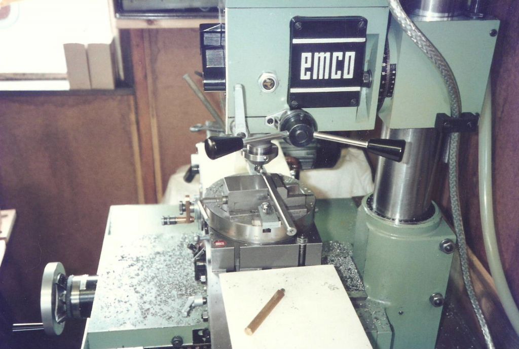
| 714 forum posts 414 photos | I have recently received many emails from around the world for more details on the various attachments and advice on owning an Emco FB2. While a lot of my attachments have appeared in print, there are some who have never read these articles. Thus I thought it would be a good idea to get a catalogue of some of the quirks, problems and attachments listed somewhere. One thing that needs to be sorted is the confusion about the FB2, Several adverts seen over the years list the 4 Speed "Mentor Mill" with its grease filled milling head as an FB2, which incidentally has a 6 speed Oil filled milling head and replaced the Mentor Mill. The number of speeds is the dead give away, as is the integral motor of the Mentor Mill, which in my experience were always Hammerite Blue, or Green. One recurring quirk or problem with the FB2 is that of Oil leakage from the Milling head. Many who have purchased a used machine automatically think it is due to a failed Oil Seal or O-ring. Of the latter there are 5 on the FB2, one large one on the Quill and two each on the shafts of the Speed change levers. Two running seals made by INA are fitted, one to the top cover and one is recessed within the Quill assembly. In the 34 years I have owned these machines I have yet to have any of these seals fail, despite near constant usage. By far the biggest culprit for oil leakage is pressurisation of the gearbox. I first noticed this when one morning after receiving the above mill. A small pool of oil appeared over night on the milling table. As the machine was only a few days old it could not be a failed seal. Leaving the filler plug slightly open cured this leak. Leaving this plug open to the atmosphere allowed the pressure inside to escape. Not being happy with the open filler I modified the standard Emco plug, then designed and fitted the plug shown below, which is basically a snifter valve.
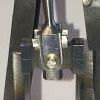
Since fitting this valve I have not suffered any further oil leaks on either of my machines. There are however some who doubt that the head does pressurise. To this end I recently carried out a simple experiment using the finger from a Nitrile glove. This is slipped over a modified sealing washer.
The next photograph was taken 1 minute later after running light at 2000 RPM
Leaving the "indicator" in-situ while carrying on working saw the finger disappear to the far corner of the workshop. Those who have not successfully tied up a Party Balloon will know the score here. I intend to add to this post from time to time. Regards Gray, |
| mgnbuk | 03/07/2020 12:05:03 |
| 1394 forum posts 103 photos | I intend to add to this post from time to time.
As a Taiwanese FB2 clone user, I look forward to the coming installments. I took the simple solution route to let mine breath by just backing off the filler cap by a turn & letting it breath through the thread clearance - not as subtle a solution as yours, Gray, but it seems to work OK. Nigel B. |
| Graham Meek | 04/07/2020 10:54:00 |
| 714 forum posts 414 photos | Hi Nigel, Over the years of owning and working with the FB2 I have tried to make things which have added to its versatility and ease of use. The green machine above was one of a pair of machines. One machine was modified in that the head was permanently on its side and the column was off-set to the right. A thick ground steel plate approx 50 mm thick was used to off-set the column. This brought the spindle back on the centre-line of the cross-slide, thus allowing more use of the table with this type of set-up. Plus the thickness of the plate allowed for tooling in the spindle with no loss of cross slide travel This machine was used mainly for edging plates and as a Horizontal Borer. This allowed me to machine plates and parts which could not be normally accommodated within the "throat" of the mill. Just remember to tighten the filler plug if you tilt the milling head to the right. I just tighten the grubscrew to put more pressure on the ball valve. This stops all but the slightest dribble of oil. Regards Gray,
|
| Graham Meek | 23/07/2020 16:52:27 |
| 714 forum posts 414 photos | The only Achilles heel with the FB2 from what I have read about is the Tufnol Gear (Gear 47 in the parts List), which some people have had some teeth stripped off.
I have seen these gears up for auction with the asking price double what a new spare part costs. As many of the parts are no longer being made by the factory. It is just a matter of time before these too will no longer be available. The last time I took the gearbox apart I took the measurements of the gear and have made a drawing. It is interesting to note that the gear is a DP, and not a Module form. Having originated in Austria I did assume the latter, until the sums just did not add up for a 45 Tooth Helical gear. One of the reasons I think these gears fail is due to owners using the lowest gear to lock the spindle to remove any Morse tooling. If one tries to turn the spindle backwards by hand in the lower range there is a feeling that something is binding, just prior to the gearbox locking up. I think it is the Tufnol gear crowding the smaller steel motor pinion. Removing a stubborn Morse taper using this method is going to put things under stress at one point on the Tufnol gear. Unlike when the machine is running and several of the teeth are sharing the load. To make the changing of tooling much easier and to remove any risk of premature breakage. I designed and fitted the spindle lock below. This makes locking the spindle dead easy and with no risk of damage to any part of the gearbox.
Over the coming months I hope to try cutting a new 45T gear by simply gashing at 8 degrees. It will not be a true helix but given the gear is 12 mm wide and the Lead is well over a metre, I don't think it will matter. It is certainly worth a try and if it works I shall have a spare to hand. Regards Gray, |
| Jim C | 23/07/2020 20:05:09 |
 76 forum posts 4 photos | Hi Graham. I own a Rishton mill which is very similar to your FB2 but with some minor differences. The speed change levers live on the left of the head and like you I have an issue with a small oil leak from the spindle. I do recall some time ago seeing your snifter valve being detailed in I think, MEW magazine but don’t have access to the drawings. Do you have them available or can you direct me to them.? Some of my 2MT tooling is difficult to remove from the spindle (may be me over tightening it?.) so I use a couple of wedges and a homemade clamp to squeeze them together. The removal mechanism at the top of the drawbar does not work for me !! does yours have such a feature. Looking forward to seeing more of the additions you have designed and hoping I can adapt them to the Rishton. Regards, Jim. |
| derek hall 1 | 24/07/2020 13:26:34 |
| 322 forum posts | Hello Graham, I am also the owner of an Emco FB2, and it also has a tell tale oil leak, never thought it was due to positive pressure in the gearbox. I laughed when I read your proof with a finger of a rubber glove though! I would really appreciate a list of articles describing the modifications that you have done on your FB2. Kind regards Derek |
| Joseph Noci 1 | 24/07/2020 15:18:48 |
| 1323 forum posts 1431 photos | Nice to see your FB2 again Graham. The FB2's may be a little light, and scorned by some for their Round Column, but they are such a pleasure to use - smooth, and very easily set up for close to zero slide play and screw backlash. I have 3 of them , in various forms, and have used them for very fine work, through to 20mm endmills and 60mm face mills hogging away in aluminium. My 'true' FB2 ; Fitted with DRO and motorized Z axis. Also some useful swarf/splash guards. Behind it is another 'FB2' - sort of..
This is an FB2, save for the actual mill spindle head. - A sturdy old British (Jones & Shipman) direct drive mill head, MT3. A 2 speed three phase motor, now driven with a VFD. This one is quite comfortable with a 60mm diameter 6 carbide toothed face mill, and will take a 2mm full width slice happily..
And the third one - converted to CNC from an old, very hammered imperial machine - replaced almost everything - all gibs, gears, bearings, quill and then fitted ball screws and a CNC setup. Works nicely..- needs splash guards though!
Regards Joe
Edited By Joseph Noci 1 on 24/07/2020 15:21:28 |
| Graham Meek | 24/07/2020 15:22:33 |
| 714 forum posts 414 photos | Posted by Jim C on 23/07/2020 20:05:09:
Hi Graham. I own a Rishton mill which is very similar to your FB2 but with some minor differences. The speed change levers live on the left of the head and like you I have an issue with a small oil leak from the spindle. I do recall some time ago seeing your snifter valve being detailed in I think, MEW magazine but don’t have access to the drawings. Do you have them available or can you direct me to them.? Some of my 2MT tooling is difficult to remove from the spindle (may be me over tightening it?.) so I use a couple of wedges and a homemade clamp to squeeze them together. The removal mechanism at the top of the drawbar does not work for me !! does yours have such a feature. Looking forward to seeing more of the additions you have designed and hoping I can adapt them to the Rishton. Regards, Jim. Hi Jim, Please find below the drawing of the Breather/Snifter Valve. I am not familiar with the Rishton as regards the filler plug thread details so you may need to check this. The 8 mm counterbore is there to stop oil that makes on the face of the standard plug making its way out of the machine. Something I learnt with the modified Std Emco plug. To size the thread I used a micrometer over 3 drill shanks on the original plug and made my new plug to that dimension.
As regards the tooling getting stuck. It may be better if I detail what I do and how the FB2 is configured. The Top of the Spindle is threaded M18x1. Onto this is threaded a Cap Nut, which accepts the head of the M10 Capscrew drawbar. This cap nut is locked onto the spindle using a 17 A/F spanner, this does not need to be excessively tight. I have introduce a washer above the the head of the Capscrew to limit how far I have to turn the Allen Key to undo the drawbar, before it contacts the cap nut. Plus this washer introduces another face for the capscrew to slide over, rather than directly on the cap nut itself. An EP grease is good at this point. I keep on the shelf behind the mill a clean lint free wipe, every tool change the new piece of tooling gets a wipe. The Morse Socket gets a clean about every 6 months with Isopropyl and another wipe. The dry surfaces of the Morse taper should be enough to hold that item of tooling during use. The drawbar is there merely to stop the tooling coming out during use from cutting forces, Helix on an endmill or slot drill, etc. I have a long series 8 mm A/F Allen Key and this is used to tighten the drawbar, but the pressure on the Allen Key is the Second Finger of my Rt Hand, nothing more. A quarter of a turn with the Allen Key is all that is required to undo and remove the tooling. Occasionally my Shell Mill holder will turn slightly under heavy cutting and tighten itself up further, but the long series Allen Key undoes the cutter with a sharp crack. I hope this helps, Regards Gray.
Hi Derek, You are not alone with regards to not thinking it is due to positive internal pressure. Some have gone to extremes to disprove what the rubber glove finger has proved. The bottom line is I have no oil leaks and my machine is 24 years old this year. Quite a few of the things I have done for the FB2 are shown in my Album, I really ought to get a list together, so you may need to bear with me on that. Regards Gray,
Edited By Graham Meek on 24/07/2020 15:27:29 |
| steamdave | 24/07/2020 16:13:46 |
| 526 forum posts 45 photos | As a former FB2 owner, (who regrets changing it for a more modern machine) I seem to remember that removing tools from the spindle was no problem due to the top hat on the top of the spindle. Just screw the top hat down and pressure was brought to bear on the draw bar, et voila - the tool was out. Dave |
| Graham Meek | 24/07/2020 16:47:48 |
| 714 forum posts 414 photos | Hi Joe, Thanks for the kind words, I am taken by your impressive line up. I particularly like the CNC conversion this looks to have been well thought out. There are times when I wished I had retained my last Green FB2. The current machine with the control panel to the front of the machine means the operator is stood further away from the machine. This is not good for my posture and I am also constantly leaning on the E-Stop button, so far it has always happened when the machine is no running. This would be my only criticism of my current machine. Regards Gray,
|
| Mark Gould 1 | 27/07/2020 21:19:59 |
| 231 forum posts 131 photos | Nice of you to start this thread Graham. Always handy to see other FB-2 machines and exchange ideas. i have made Grahams most excellent spindle lock.
|
| Graham Meek | 28/07/2020 10:33:54 |
| 714 forum posts 414 photos | Thanks Mark for adding your latest FB2 enhancement, also for giving me a reminder. I must get on and gather up some more items for you and this post. Regards Gray, |
| Mark Gould 1 | 29/07/2020 09:13:06 |
| 231 forum posts 131 photos | Thanks Gray, you did say you needed the occasional prod |
| Versaboss | 30/07/2020 22:51:16 |
| 512 forum posts 77 photos | I have sold my Emco mill, but know the buyer. For an easy solution to the oil problem, would it be possible to drill a say 1 mm hole through the hex key opening, and then fill that opening with a piece of foam or plastic sponge. Air can escape, and dirt cannot go in. Kind regards, |
| Graham Meek | 31/07/2020 10:57:20 |
| 714 forum posts 414 photos | Hi Hans, The modified Emco plug in my drawing above, started out in exactly the same way as you describe, before I added the spring loaded valve. The problem with the Emco plug is two fold. The end of the plug is flush with the inside of the gearbox cover. Oil accumulates on this surface during use. When the quill is lowered and then raised droplets of oil from the end of the plug are carried into the foam. The second problem is with continued usage this oil builds up in the foam and starts to leak over the outer surface of the cover. This returns the Status Quo, and there is another oil leakage. Even using the spring loaded version of the Emco plug, this allowed the oil to accumulate in the hex socket. Every so often when using the quill I used to get this spray over my safety glasses, the small hole makes an ideal spray nozzle arrangement. This usually occurred immediately after I had just cleaned the safety glasses. This is why in the final design there is an 8 mm counterbore in the end of the new plug to stop the initial oil accumulation. As with all designs, the Devil is in the detail. Regards Gray,
|
| Graham Meek | 31/07/2020 15:17:05 |
| 714 forum posts 414 photos | An item I have had on trial for a while is a set of Adjustable Stops for the Emco Rotary Table. These are in-valuable when two radii have to meet, or intersect. As the Stop takes away any chance of an over-run with the table, or turning the handle in the wrong direction.
I was using this today on the Main Support for the Lathe Tool Honing machine I am building and described on a separate post.
Also in use is something I made over 30 years ago, and shown above the graduations in the next photograph. It is a simple stepped and slotted Hold-out Washer.
This sits beneath the indexing pin handle on the Rotary Table, there-by keeping the pin out of engagement with the Dividing Plate. This is a real boon when circular milling. It takes minutes to make but saves hours of frustration.
Also in the shot is my revised X-Axis Stop and move-able cursor holder. More on that another time. Regards Gray, Edited By Graham Meek on 31/07/2020 15:18:48 |
| Kiwi Bloke | 01/08/2020 07:46:38 |
| 912 forum posts 3 photos | Gray, it looks as though you are entirely successfully using your (modified) Emco 'Indexing Unit' as a rotary table, for machining slots and other curved surfaces. One would have thought that Emco intended it to be used this way, as well as for angular positioning and indexing, but the FB-2 manual states unambiguously that the table locks should be tightened before any machining. This would explain their decision not to name the thing an indexing rotary table, I suppose. But why make something that is almost a rotary table, and then instruct users not to use it as a rotary table? Strange. Several years ago, when I looked at my unit, I was surprised to see that the worm's axial constraint effectively depended upon on the nut securing the handle, and there was no provision for end-float adjustment. Also, even with the eccentric worm carrier turned to maximum worm engagement, there was significant angular backlash at the table (as far as I remember, the worm was not moving axially). I wasn't impressed, and supposed that the unit really wasn't designed to be used for anything other than angular positioning. I had other rotary tables to use for arcuate machining, so I didn't pursue it any further. What are your thoughts? Have you modified the wormshaft's location arrangement? Another possibility for adding stops to rotary tables is one or a pair of bands, incorporating tightening scews, which clamp to the table's periphery. A radial projection from each band can then contact a stop fixed to the unit's body. (Think glorified Jubilee clip, if my description isn't clear). |
| Graham Meek | 01/08/2020 11:24:46 |
| 714 forum posts 414 photos | Hi Jerry, I understand the confusion with the Emco Rotary Table, given the Manual only describes an indexing function. As far as I was concerned the attachment was both from the start of owning Emco products. It would have been better if Emco had chosen a 60:1 ratio as regards using the attachment as a Rotary Table. The 40:1 ratio is a bit fast for circular milling but you get used to it, although somewhere in my drawing files I have a 60:1 worm and wheel conversion drawn up. I used the attachment as both Dividing Head and Rotary Table until I had a chance to design my own Dividing Head.
This is a marriage of GHT's Versatile Head, the Emco Rotary Table, the Emco machine Vice swivel base and a bit of Meekising. As regards the end float on the Worm Shaft. In the normal Emco design all float is taken up by a special Bellvue Washer with a cut-out in it to clear the locking screw of the sector arms on the indexing plates. This serves two functions in that it provides friction to make sure the sector arms stay put, but also to take up the play in the worm shaft bearing. This is fine for indexing, but when it comes to circular milling it has an Achilles Heel. Provided the cutter rotation and rotary motion of the table are in sink, everything is fine. If however the rotary motion is using the Bellvue washer as its resistance to the cutting forces things can get a little hairy with a tendency for the cutter to snatch. To this end I have done away with the Bellvue washer arrangement and fitted a special spacer to take up the backlash. I use the same arrangement on my Dividing head, and feel I had better take some photographs of that. One photograph saves a thousand words, the special spacer can just be made out in the last photograph of my last post. As regards the depthing of the worm in the worm wheel. In the M8 Tee Bolt slot for holding the Rotary Table down to the cross-slide or milling table there is a Slotted Grub Screw that acts as a stop. This is screwed in or out to get the desired adjustment, but you will need just a little play. Hope this helps, Regards Gray,
Edited By Graham Meek on 01/08/2020 11:29:12 |
| Kiwi Bloke | 02/08/2020 10:56:22 |
| 912 forum posts 3 photos | Thanks Gray, very helpful - I don't remember considering experimenting with adjustment of the 'slotted grub screw'. I must dig the table out and play... Your other comments (and the manual) lend more evidence to my suspicion that Emco didn't consider the thing to have been designed for arcuate milling. What an odd oversight. However, Emco seem to have had other surprising design blind spots - the Unimat 3 vertical unit's quill spindle bearings (sloppy and unadjustable) and the early Compact 5's cross-slide feedscrew nut being integral with the table (no adjustment possible), to name but two. I'm eagerly awaiting further details of your FB-2 enhancements... |
| Graham Meek | 02/08/2020 16:02:52 |
| 714 forum posts 414 photos | Hi Jerry, I think given the number of machines that have come out of the Emco works which have enhanced the Home Machinists lot quite considerably, I can forgive them one or two oversights. We are not really in a position to know what the designers criteria was at the time. Some of the things were probably done to ease production / assembly. Plus there may have been a maximum unit price to work to. Regards Gray,
Above is a view of the mods done to the rotary table Worm shaft to eliminate backlash, or the spring effects of the Emco standard set-up shown below, and mentioned above. Thirty years of wear can just be made out on the end face of the slotted distance piece. The slotted Grub screw for adjusting Worm to Worm wheel engagement can be seen at the bottom of the M8 hold down slot. This needs to be removed from the tapped hole if ever the eccentric sleeve needs to be removed completely. Also in the shot is the O-Ring in the Sector Arms used to provide the friction that the original Emco Bellvue washer was providing to make the Sector Arms stay put during Indexing moves.
On the Table of the RT is a view of the other side of the slotted distance piece.
As promised earlier here is a photograph of the Adjustable X-Axis Cursor holders. The Original one was obscured by the machine vice when in use. In all fairness to Emco this is I think due to the fixed jaw of the vice being parallel to the X-Axis movement. I have noticed the fixed jaw is often shown at 90 degrees to the X-Axis on the Continent. With the vice in this position it does not obscure the cursor. The reason for the two cursors is for visibility down each side of the vice. When one is covered the other is always exposed. When using the RT the Rt Hand cursor is removable so that the Lt Hand cursor can be transferred to the Rt Hand station. The Indexing plate of the RT fouls the cursor in the Rt Hand station and from memory It can mark the original Emco cursor set-up.
More little Quirks to follow, Regards Gray, Edited By Graham Meek on 02/08/2020 16:08:00 |


Please login to post a reply.
Magazine Locator
Want the latest issue of Model Engineer or Model Engineers' Workshop? Use our magazine locator links to find your nearest stockist!
Sign up to our Newsletter
Sign up to our newsletter and get a free digital issue.
You can unsubscribe at anytime. View our privacy policy at www.mortons.co.uk/privacy
Latest Forum Posts
- *Oct 2023: FORUM MIGRATION TIMELINE*
05/10/2023 07:57:11 - Making ER11 collet chuck
05/10/2023 07:56:24 - What did you do today? 2023
05/10/2023 07:25:01 - Orrery
05/10/2023 06:00:41 - Wera hand-tools
05/10/2023 05:47:07 - New member
05/10/2023 04:40:11 - Problems with external pot on at1 vfd
05/10/2023 00:06:32 - Drain plug
04/10/2023 23:36:17 - digi phase converter for 10 machines.....
04/10/2023 23:13:48 - Winter Storage Of Locomotives
04/10/2023 21:02:11 - More Latest Posts...
- View All Topics
Support Our Partners


Shopping Partners
Subscription Offer

Latest "For Sale" Ads
- Reeves** - Rebuilt Royal Scot by Martin Evans
by John Broughton
£300.00 - BRITANNIA 5" GAUGE James Perrier
by Jon Seabright 1
£2,500.00 - Drill Grinder - for restoration
by Nigel Graham 2
£0.00 - WARCO WM18 MILLING MACHINE
by Alex Chudley
£1,200.00 - MYFORD SUPER 7 LATHE
by Alex Chudley
£2,000.00 - More "For Sale" Ads...
Latest "Wanted" Ads
- D1-3 backplate
by Michael Horley
Price Not Specified - fixed steady for a Colchester bantam mark1 800
by George Jervis
Price Not Specified - lbsc pansy
by JACK SIDEBOTHAM
Price Not Specified - Pratt Burnerd multifit chuck key.
by Tim Riome
Price Not Specified - BANDSAW BLADE WELDER
by HUGH
Price Not Specified - More "Wanted" Ads...
Get In Touch!
Do you want to contact the Model Engineer and Model Engineers' Workshop team?
You can contact us by phone, mail or email about the magazines including becoming a contributor, submitting reader's letters or making queries about articles. You can also get in touch about this website, advertising or other general issues.
Click THIS LINK for full contact details.
For subscription issues please see THIS LINK.
Digital Back Issues


Donate

 Register
 Log-in
Model Engineer Magazine
- Percival Marshall
- M.E. History
- LittleLEC
- M.E. Clock

ME Workshop
- An Adcock
- & Shipley
- Horizontal
- Mill

Subscribe Now
- Great savings
- Delivered to your door

Pre-order your copy!
- Delivered to your doorstep!
- Free UK delivery!
All Forum Topics > Manual machine tools > Emco FB2 Quirks and Additions