Member postings for Sam Stones
Here is a list of all the postings Sam Stones has made in our forums. Click on a thread name to jump to the thread.
| Thread: Cutting speed theory |
| 23/04/2011 06:53:01 |
|
Further to my previous posting, I have to say that I haven’t been grocery shopping this week. That is the domain of my dear wife. So, although there have been no requests for a photograph,
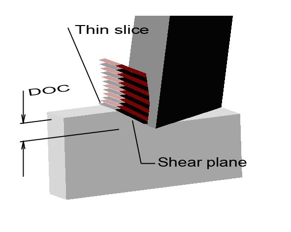 My hypothetical diagram is based upon a simple cutter (tool bit) shaped like a wide parting-off tool, and placed as if it were installed in a toolroom shaping machine or indeed a planer. The tool bit is tilted back at an angle of 10 degrees to provide top rake, while the underside (actually known as the front face or end relief angle) is also backed off by 10 degrees. For simplicity, the workpiece is narrower than the width of the cutter. As usual, DOC indicates depth of cut. Although I have tried to explain this in my previous posting, the diagram and a few more words may help.
As the cutting tool first makes contact with the workpiece, the metal of the workpiece starts to be compressed locally ahead of the cutter. Suddenly, when the compressive stress exceeds the shear strength of the metal, the metal gives way at an angle to the direction of tool travel. (This angle is known as the shear plane, and is related in particular to the metal properties and the top rake of the cutting tool. There will be ME readers who can no doubt, explain the theory better than I.)
Driven by the advancing cutter, this thin slice of metal momentarily `slides’ over the workpiece along the shear plane. Almost immediately, the shearing action stops, and the tool tip begins once more to compress the metal of the workpiece. Again a thin slice of metal is `dislodged’ and slides over the workpiece. The process is repeated at a rapid rate, and a ribbon of swarf curls off the tool tip. It is usual to see the shark-skin appearance on the inside face of a piece of swarf.
For clarity in my diagram I have shown the thin layers in alternate colours. Clive has clearly indicated that there is a lot of heat energy generated during this shearing action.
This reminds me of the time when I was bending down near a shaper already `cutting’ metal. While searching for some bolts and clamps in a tool box, a very hot piece of swarf landed on my head. As I tried to brush it clear, it wrapped itself around my finger while still hot enough to continue to burn anything it touched. There was a strong smell of burning hair and skin, and my language was not that of a gentleman.
 Regards to all,
Sam
Edited By Sam Stones on 23/04/2011 06:57:03 Edited By Sam Stones on 23/04/2011 07:02:52 |
| 21/04/2011 04:57:47 |
|
Hi Norman, Although I have stood for many hours watching swarf in many forms as it leaves various machine-tools, and can remember a little about Mohr’s Circle as applied to metal cutting theory, I cannot venture too far down this burrow. It is unfortunate however, in the context of metals, that we use the word `cut’. I say this because the action is more complex. For simplicity, I’m basing my comments upon the action as seen during the surfacing of a round bar of metal in a lathe. The way I understand it, (and I have a simple way to demonstrate it), the so called `cutting’ action commences when the tip of the tool-bit first bites into the metal and causes the material of the workpiece to momentarily fail in compression. Almost immediately, as the stress level builds up, the material ahead of this compressed portion fails in shear. The failure takes place at a specific angle referred to as the shear plane.
Almost immediately, this shearing action stops, and the compression process begins again. The stop-start process is repeated at a rapid rate as can be seen by examining the `inside’ and `outside’ faces of the swarf.
Let it cool first!!! It is usual to see a form of rough `shuttering’ or shark-skin on the inside face of the swarf, while the outside face appears `polished’. This polishing is a result of the material being compressed and then burnished as it slides over the top face of the tool-bit. The shuttering is evidence of the stop-start failure pattern. The shear plane varies from metal to metal, and will also be influenced by the angle of the top rake. Beyond this, and in terms of the energy dissipated, etc., I am out of my depth. I can however, invite you to explore the action using a fresh tub of margarine from the fridge, and a normal table knife. Between meals and with the permission of SWAMBO, the kitchen is a wonderful place to investigate. For this test, the knife does not have to be sharp. Taking hold of the knife as if you were about to `butter’ a slice of bread, tilt the blade at right-angles to the surface of the margarine. Starting from one side and with the blade pressed into the margarine a few millimetres, sweep the blade across the surface is if it were a planing tool. Given that you have got the angle about right, you should see (stuck to the knife) an enlarged version of a piece of metal swarf. If, for any reason, especially if SWAMBO is hovering around, and you need a bit more detail, I’ll shall be quite happy to take a photograph or two and plonk them into the thread. Good luck! Sam Edited By Sam Stones on 21/04/2011 04:59:40 Edited By Sam Stones on 21/04/2011 05:01:14 |
| Thread: Technical and engineering drawing. |
| 21/04/2011 01:26:29 |
Hi Les,
Goodonya moyte.
With the cat out of the bag, the cat among the pigeons, and more ways to skin a cat, all should be clear.
Sam
PS My Australian wife reckons my Ozzy accent is way off.
|
| 21/04/2011 01:15:00 |
Len, (our Merry Miller), has made an interesting point.
As they appear to be fond of the number eight, wouldn't BS 8888 be aimed at the Chinese market?
Sam
(Tongue in cheek) |
| 21/04/2011 01:03:23 |
|
Gentlemen,
With the cat out of the bag, Nick has shown one of the solutions and has clearly used 3rd angle projection.
Or has he? Don’t take this personally Nick, because (I hope) I’m trying to bring attention to an important part of Terry’s original idea. If it were (all) 3rd angle dangle, sorry projection, shouldn’t the small square of my original PLAN view be dotted? And where should the PLAN view be positioned to avoid this? In the words of `Top Gear' James May "Oh cock!" While, from a young age, I learned to draw in 1st angle (as a Pomme - English projection comes naturally), I have become `tolerant’ to 3rd angle projection, a method better suited to drawing very long objects such as aircraft and ships. However, I still maintain (and have taught for many years) that 1st angle is by far the better system for moulds of the injection type. In the plastics industry (especially this country), countless drawings are constructed in 3rd angle, an Australian industry `standard’. Sadly, the views and sections end up in all sorts of weird positions, contradicting the basic rules of 3rd angle, and showing little to no resemblance of how the mould is positioned in the moulding machine. Then along came CAD. This was the door which opened us up to the wonders of 3D solid modelling but, I believe, caught a lot on the hop. To keep pace with a changing world, they had to learn CAD, and with most commercial software, months of training was often required (and still does). Personally, other than the cost, I found 3D CAD a delight, and only look(ed) upon 2D as a means of initial construction or when conveying information when my client requested dimensioned (paper) drawings via the plotter. Perhaps we should wait a little longer for someone to show us other alternative solutions to what has become known here as Sam’s test!? Best regards to all who sail in her, Sam By the way, is a nurd, (nerd, nurd), Imperial or Metric? Edited By Sam Stones on 21/04/2011 01:07:36 |
| 20/04/2011 05:32:27 |
|
Geoff, Thanks for your comment. Bob Sheppard (from Harper Green Secondary Modern School, in Farnworth c.1946) holds a very important place in my memory. Tony, I think you’re right. Where are all the responses to the test? Yes, I think you’re right too Steve. It must be too simple a test. I have another anecdote for those of you who are enjoying Terry's thread. I must preface mine by saying that Melburnians have an expression about exposing ones posterior in Burke Street, so here goes. In the late 50's, it became necessary to redesign the outer casing of a toilet cistern. At that time, the casing and lid were being compression moulded from a composite of pitch and other reinforcing materials. The `new’ material was the much more modern thermoplastics polypropylene (PP), and had become commercial around 1957. Unlike the pitch compound, PP could be injection moulded. The specification also included that the existing innards of polyethylene ball valve and syphon, and various metal fittings were to remain. The cistern casing was designed for both `high’ level and `low’ level operation, and for greater adaptability, was identical left to right. It was necessary with this `new’ material to provide parallel wall thickness by local thickening the five inlet/overflow/outlet positions, thus forming `bosses’ on the ends and underneath. The next task was to design and detail the tooling (injection moulds). Eventually, I had produced about half a dozen sheets of tool drawings for the cistern’s lower half. These drawings, having passed through the checkers hands a couple of times, and gained approval at various other levels, were sent off to a German toolmaker. Two injection moulding machines were duly ordered and installed, and after about 6 months the cistern and cistern lid moulds arrived. "Have a look at this!" It was the chief draughtsman. One of the end bosses was missing! But how could that have happened? It turned out that on the GA and also in detail, (having sectioned the mould through various planes to show the feed arrangement, water circuits, air ejection, etc. etc.), I had inadvertently omitted to show that the cistern was actually symmetrical about the vertical centre line. The toolmakers had gone ahead and worked exactly to my drawing. Eventually, the problem was rectified, but by this time I had (coincidentally), taken on a new position with a major raw-material supplier. This company supplied PP, the very supplier of the grade being used for the cistern!!!? Guess what? The bl . . y cistern followed me there with another problem. But that’s yet another story. They say things come back to haunt you. But surely not twice. A couple of evenings ago, my wife and I were watching a very early `On the Buses’ episode. Bus driver, Stan Butler was replacing their old toilet cistern with a modern low-level version, and as usual, he was getting into all sorts of bother. You’ve guessed it! He was installing the very same cistern which I designed (and helped to screw-up), all those years ago.
AND, the point is, besides following my story, have you understood some of my deliberately placed design engineering jargon? If not, then Terry's objective gains more validity.
Best regards to all,
Sam
Edited By Sam Stones on 20/04/2011 05:33:50 Edited By Sam Stones on 20/04/2011 05:35:29 |
| 19/04/2011 23:16:58 |
Some of you guys are working late, but it's nice to get up in a morning and find so many postings.
Sam
Melbourne time = 08:15 |
| 19/04/2011 02:52:29 |
|
At midday in Melbourne, there are 61 responses after less than two days. That is saying a lot about Terry’s idea.
I was also expecting more responses with regards to the little test. Are you too embarrassed to speak up?
No, it’s not a trick question Nick. It has everything needed to construct the SIDE elevation, and makes the point about `reading’ a drawing and the need for acceptable standards. Have a look at Steve Garnett's posting on 18/04/2011 13:46:13. He mentions SWMBO and her `instant’ recognition of the missing view. Congratulations to her! Hi Dick, And I thought I was old.
Terry, You mentioned Spatial Awareness. That’s something quite a few engineers appear to lack. Geoff, Could it be that you are related to the man who most inspired me at school? His names was Robert (Bob) Sheppard and taught Practical Drawing at a Lancashire Secondary Modern. Steve, I was delighted when (c.1960) we switched to ink drawing and `Page’ pens, and were able to get rid of all that graphite dust. Mind you, mistakes needed to be erased with an electric eraser, which could easily burn a hole through the tracing paper.
I’m probably babbling on too much, but . . . at a factory producing a wide variety of plastics mouldings (in those days they were thermosetting materials), we had to `tool up’ for a Bakelite switch plate. It was one of those small but extremely complicated shapes with faces, angles and curves which only a switch manufacturer could invent. To make sure we had all of the correct dimensions, it was decided that we should reconstruct the drawing from the dimensions provided. No matter which way we tried, we couldn’t get any part of the drawing to meet where it should have met. Finally, the drawing was sent back to the customer so that they could review it and offer comment. I can’t recall the outcome, because I moved on to work with another company, but this was another example of why drawing standards and an ability to be able to read them are important.
When I was first introduced to Automotive Industry drawings here in Australia, (having been fully indoctrinated into 1st angle [English] projection), it felt as if I was being introduced to an appalling mess. It was 3rd angle with reference points somewhere in the middle of the vehicle. It was also hard to distinguish between construction and product outlines, because they were all the same thickness. Ugh! Let me say also (as if it weren’t obvious), that I delight in seeing the old stuff , like the escapement drawing in `With the Watchmaker at the Bench’ by Donald De Carle c.1933, a style I often tried to emulate.
Here's a copy . . .
 Regards to all,
Sam I wonder where the yellow went?
|
| 18/04/2011 08:36:29 |
Frayed so, Dick.
Most of my nuts are old and hoary.
 But, I'll bet it wasn't 1948 when you were shown it. You couldn't be that old!?
ady, You could be on to it !
Sam Edited By Sam Stones on 18/04/2011 08:41:44 |
| 18/04/2011 01:38:52 |
 Further to Terry's and other postings, how about a little test? If you already know the answer, please keep it to yourself for a few days. If you don't know the answer and can't work it out either, then post a reply to that effect.
The test is simple, but is intended to help to determine if Terry's idea is a popular one.
The two views (FRONT and PLAN), are drawn in first angle (English) projection (not third angle). Tutt Tutt Sam!!!
 There are no missing lines on either of the views shown, neither full lines nor dotted (dashed). With your knowledge of engineering drawing can you construct the side elevation (above the word `SIDE')?
By the way, although I worked out the answer at secondary school when I was thirteen, have also been `doing' engineering drawing since about 1948, and have taught various levels of engineering drawing (mainly applied to other subjects), I have no idea what BS 308 looks like. Another Tutt Tutt.
 Regards to all,
Sam |
| Thread: Help! |
| 10/04/2011 03:31:36 |
|
Hi Richard,
I have to return my `T’ shirt, because it’s too long ago to remember anything about the flux, and I can only guess at what (grade of) metals I used. I think the steel was high carbon (probably silver steel), and the brass was `off-the-shelf bar from the local supplier. I/we took no measures to release the flux/gases. When I say `we’, I made the parts in my own workshop, and then took them into work where they had the oxy torch.
I recall making the brass ring a tight fit onto the (interface) diameter of the steel `sink’ and, before fluxing, I made absolutely sure that everything was clean. An old RAF trade-training catch phrase was `Clean and Tin’. But that was for soft soldering electrical work. Upon scanning the 1972 ME (five part) article, it would appear that I actually deviated from John Stevens design of a one-piece brass wheel, and followed the bi-metallic design as described by Gazeley. What was I thinking??? I have no real experience of rolling except from forming some 1/16" aluminium sheet into large cylinders about 8" diameter and 5" long. They were casings for the lights of some TV show or other. Again too long ago. However, with respect to its visibility, unless you obtain a truly round wheel, it will look somewhat primitive as it oscillates. That has been one of the issues I’ve had to address wrt the helical balance spring in my clock. In other words, unless the wire of the spring is accurate in pitch, diameter, and held central at both ends it will `wobble’ and look odd. I think you have started at the right `end’ of the clock, because once you have determined the `beat’, then the gear(box) design should be relatively simple. Good luck, Sam |
| 09/04/2011 01:27:16 |
|
Hi again Richard, Without too much thought, an obtuse idea momentarily traversed some of my neurons. Since you have actually contemplated using tin cans, could you apply sufficient brass to a flat strip of steel, and then carefully bend the result (with the brass on the outside), to become your wheel rim? After all, the rim will (normally) be in two semicircular pieces. To remain ductile, I imagine that the brass would need to be annealed progressively as you bend (or roll) the strip to the desired radius.
Clearly, there would need to be plenty of brass, and even an excess of steel, for the lathe work to produce the proper article.
Sam Edited By Sam Stones on 09/04/2011 01:28:53 |
| 09/04/2011 00:22:40 |
|
Hi Richard,
I feel sure that you will have already perused the ME Forum for ideas!? If not, then insert `Balance’ into <Keyword> and `Clocks’ in <All Topics>, this brings up several posting about issues I had with balance wheels and balance springs. In particular, they highlight some of the `struggles’ I’ve had with the escapement of my skeleton clock. Clearly, the larger size of your intended wheel is likely to introduce additional challenges, which may not have surfaced during the time I was making my balance wheel, c.1973 Suffice it to say that I had five attempts at fusing the brass ring into the steel sink. To get enough heat, and with the help of a friend, I/we resorted to the use of an oxy-acetylene torch.
The primary causes of failure were non-fusion of the brass to the steel, and blow holes in the brass. I put the former cause of failure to insufficient heating and melting, while the blow holes may have been due to trapped flux escaping up through the brass. No doubt the heavier brass was displacing the melted flux (and/or gases). My final attempt (which can be seen in one or two of my pictures) still displays a couple of tiny blow holes. I must also admit to getting wrong, the thickness ratio of brass to steel, and trust that there will still be enough temperature compensation for a reasonable time-keeping result.
As for the spring, that was becoming quite a saga, for me at least. However, thanks to the generosity of one of you gentlemen, I have been sent a spring which has all the makings of a very close approximation to the recommended design. When I’ve regained some of my health, and the cooler Melbourne weather is upon us, I intend to pursue this to completion. If not, SWAMBO will descend upon yours truly.
Good luck,
Sam |
| Thread: Junk or what? |
| 06/04/2011 01:10:07 |
Good morning gentlemen!
Congratulations must go to Thor, Peter, Nick, Norman, Andy, Gordon, Andries, and Derek for their correct guess. AND, a big thank-you for everyone else who contributed. If you guessed that it was a section of a wooden water main, you were spot on. That’s a good website Andy!
I had a good laugh at your suggestion Terry, especially since the pipe measures almost 24" (600mm) diameter. I’d expect that it would require an oversized mouth and produce a note so low that only whales would be able to hear it. Now here are the details to accompany my photographs in my album marked "A Load of Junk?" :-
About a kilometre from where my wife and I live, engineers are installing and coupling a new gas pipe into the current system in order to boost the gas pressure. During the excavation process reaching down to a depth of about 3 metres, a section of an old water main was severed to make way for the new pipe and some valve gear. It was this piece of pipe which had been torn up, and placed near the walking track which our dog and I use every morning. At first, I thought the pipe was just a bit of an old farm drain shoved under the track, but it was the construction which really caught my eye. So later in the afternoon, camera in hand, I set off.
As I was about to take photographs, one of the engineers came over to see what I was doing.
"What is it?" I asked. "It’s a piece of a wooden water main, perhaps a hundred or more years old." he explained.
I later checked on the Internet, and discovered that in Australia, these pipes could have been layed in the late 1800's. We chatted a bit more about the pipe's construction, then I took a string of pictures.
The pipe measures about 23" inside diameter, and the inside layer is made up of 22 strips of red gum, which appear accurate enough and fit together very neatly to have been machined inside and out. (See my diagram). Besides being curved in profile, they are partially tenoned with `V' shaped (90 degree) tenons. Wrapped around the layer of red gum is a layer of 5/16" diameter steel wire, which has been wound around at about 13/16" pitch. A third layer covers the wire and appears to be felt-like. This is heavily coated in bitumen which was still sticky to the touch. Upon further examination, the inside of the pipe may have been coated with a cement-like substance, although this may be just a coating of silt. My photograph of the inside of the pipe seems to indicate that the bottom of the pipe was on the left, while on the right, there is just a small amount of surface rot. There is clear evidence that the pipe was made in sections and spigoted one end into the next. However, it wasn’t possible to determine the length of a section of this pipe since some of the piece was still in the ground. The condition of the wood is quite remarkable, with hardly any signs of rot. Similarly, the steel wire has been well protected from rusting.
What sort of pressure must this pipe have had to endure, if the pipe were running full from a mountain water supply? The engineer said he would like to know how they arranged a bend in a pipe of this design. There can also be quite large forces in play as the water changes direction.
So far, I haven’t found details of a pipe of this type of construction, which come anywhere near 24" diameter. That would also explain why the steel wire was wrapped around with such a close pitch.
As for my skeleton clock project Norman, a series of health issues have distracted my attention somewhat, as has working in an over hot garage.
Best regards to all,
Sam Edited By Sam Stones on 06/04/2011 01:17:48 |
| 05/04/2011 09:07:10 |
Under the Southern Cross I Stand A sprig of wattle in my hand, A native of my native land, Australia you little beauty
A good try Richard, but . . .
Best regards,
Sam
Edited By Sam Stones on 05/04/2011 09:07:55 |
| 05/04/2011 04:30:14 |
I went back this morning to take some more pictures, and some bu. . . .er (sorry, someone) had nicked it.
Anyway, here's another picture I took yesterday, to provide you with a closer look.
 Notice the rings pressed into the black stuff, and the join lines running along the length. Tomorrow, I'll post some more pictures. It will then be clear to all what a surprising bit of junk this really is.
Regards,
Sam
Edited By Sam Stones on 05/04/2011 04:31:09 |
| 05/04/2011 01:24:46 |
Steve,
No, it's got nothing to do with kangaroos or any other type of non-human animal.
Could this be another clue?
OK, here's my next clue - I'm told that it could be more than 100 years old!
Sam |
| 05/04/2011 00:03:03 |
Cos it wouldn't be metric. |
| 05/04/2011 00:00:08 |
Andrew Johnston! Naughty boy!
5/16" was meant to be my Third Clue.
Who knows which direction our current politicians are going. They appear to be clue-less.
Sam |
| 04/04/2011 23:28:28 |
|
Second Clue - The wire is 5/16" (0.8mm) diameter steel. |
 I don’t have a fresh tub of margarine to demonstrate the action of how metals actually `cut’. Instead, I’ve cobbled up a simple diagram to show what I remember of the so called `cutting’ action.
Magazine Locator
Want the latest issue of Model Engineer or Model Engineers' Workshop? Use our magazine locator links to find your nearest stockist!
Sign up to our Newsletter
Sign up to our newsletter and get a free digital issue.
You can unsubscribe at anytime. View our privacy policy at www.mortons.co.uk/privacy
Latest Forum Posts
- hemingway ball turner
04/07/2025 14:40:26 - *Oct 2023: FORUM MIGRATION TIMELINE*
05/10/2023 07:57:11 - Making ER11 collet chuck
05/10/2023 07:56:24 - What did you do today? 2023
05/10/2023 07:25:01 - Orrery
05/10/2023 06:00:41 - Wera hand-tools
05/10/2023 05:47:07 - New member
05/10/2023 04:40:11 - Problems with external pot on at1 vfd
05/10/2023 00:06:32 - Drain plug
04/10/2023 23:36:17 - digi phase converter for 10 machines.....
04/10/2023 23:13:48 - More Latest Posts...
- View All Topics
Support Our Partners


Shopping Partners
Subscription Offer

Latest "For Sale" Ads
- Reeves** - Rebuilt Royal Scot by Martin Evans
by John Broughton
£300.00 - BRITANNIA 5" GAUGE James Perrier
by Jon Seabright 1
£2,500.00 - Drill Grinder - for restoration
by Nigel Graham 2
£0.00 - WARCO WM18 MILLING MACHINE
by Alex Chudley
£1,200.00 - MYFORD SUPER 7 LATHE
by Alex Chudley
£2,000.00 - More "For Sale" Ads...
Latest "Wanted" Ads
- D1-3 backplate
by Michael Horley
Price Not Specified - fixed steady for a Colchester bantam mark1 800
by George Jervis
Price Not Specified - lbsc pansy
by JACK SIDEBOTHAM
Price Not Specified - Pratt Burnerd multifit chuck key.
by Tim Riome
Price Not Specified - BANDSAW BLADE WELDER
by HUGH
Price Not Specified - More "Wanted" Ads...
Get In Touch!
Do you want to contact the Model Engineer and Model Engineers' Workshop team?
You can contact us by phone, mail or email about the magazines including becoming a contributor, submitting reader's letters or making queries about articles. You can also get in touch about this website, advertising or other general issues.
Click THIS LINK for full contact details.
For subscription issues please see THIS LINK.
Digital Back Issues


Donate

 Register
 Log-in
Model Engineer Magazine
- Percival Marshall
- M.E. History
- LittleLEC
- M.E. Clock

ME Workshop
- An Adcock
- & Shipley
- Horizontal
- Mill

Subscribe Now
- Great savings
- Delivered to your door

Pre-order your copy!
- Delivered to your doorstep!
- Free UK delivery!