Member postings for Sam Stones
Here is a list of all the postings Sam Stones has made in our forums. Click on a thread name to jump to the thread.
| Thread: Super Glue & Balance Springs |
| 02/07/2011 01:56:22 |
|
Hello again, especially Dick, Ian, and Norman, Thank you for all your ideas, I really appreciate getting your type of assistance. Just a couple of points about the use of guitar strings, and also in making extra equipment. At the risk of repeating my earlier comments, my target is to finish the clock while I still have some dexterity left. I also consider my workshop to be a very temporary affair, and am reminded on occasions that the Hobbymat lathe is, after all, still on loan. As some of my pictures show, the mechanism of a skeleton clock is intended to be fully visible. That’s the primary purpose of piercing the frames and wheels. In the case of John Stevens clock, the most obvious animation is the balance wheel and spring sitting inside the top `cage’. The nice thing about steel guitar strings, is that they are already polished. So if I can keep them in that condition, there will be less effort needed to bring them up to scratch. I would agree however, for those who like that sort of thing, that the spring could be a nice blue colour after tempering, but once again . . . I like Ian’s idea of passing a low voltage current through the wire to soften it. I did notice that being rather fine, the wire burns immediately (like wire wool) if placed in a naked flame. I could also imagine that with care, the use of electrical current in this way, could be employed in both the rehardening and tempering after the wire has been wound to size. Holding it to shape would be quite a challenge however. In my next comment, if not before, there is likely to be an element of `egg-sucking’ for grandmas. However, I’m inclined to believe that winding the wire around a 4mm diameter mandrel to get a finished diameter of about 8mm, does actually subject a percentage of the steel section to stresses above the elastic limit. How much of this will be in tension (or compression), I could not imagine. Clearly, there would also be a certain % of the section which does not get stressed beyond the yield point, or the spring would come off a 4mm mandrel at 4mm without any `snap-back'. Machinery’s Handbook offers a table for Arbor Diameters for Springs Made from Music Wire and although it doesn’t actually mention the OD I needed, by extrapolation and my own tests, I seem to be on the right track at 4mm. In terms of `annealing’ (I have difficulty with the definition of annealing), early tests of heating previously wound coils to about 200 deg C showed very little relaxation, and all the wire that I have wound since remains very close to what I wanted without this treatment. Finally, and switching to Norman’s comments about the case (thank you Norman), and where to buy them, I have elected to follow John Parslow’s approach. Refer ME p202 15 August 2008. It concludes John’s article called "15-day skeleton timepiece". With the help of a friend with some good woodworking machinery, I now have a pine base suitably stepped, together with some pieces of Tasmanian oak beading to trim the surround. The ends of the beading have been mitred which is a task I have never enjoyed via the hand-sawing method. I’m currently waiting for some shellac to dissolve and before I glue I will begin to apply this to the oak in multiple coats alternating with a rub-down with fine sand paper. I trust that PVA will hold everything together. The centre area of the base (inside the glass) will be covered in a dark blue material, the sort of cloth that is turned into tracksuits and the like. There’s a glass supplier down the road who has made fish tanks and display cases, so I’ll be talking to him next week. Alternatively, I’ll get him to cut the five pieces of glass, and glue them in place with clear silicone. Depending upon how the silicone runs between the glass, I imagine knifing off the excess to leave a very clean joint. I reckon the French polish will be ready by now. Regards to all, Sam Edited By Sam Stones on 02/07/2011 02:06:00 |
| 01/07/2011 08:56:51 |
|
Looks like my editing needs a shake-up.
I've just discovered that my last few paragraphs dropped off the end.
Please pick up from :-
It Failed!
Have you ever bought 3ml tubes of super glue, and found that they contain less than half a ml? But that’s another story. Super glue sets as it combines with moisture in the atmosphere. It also dissolves in acetone. You get my picture? I was down to my last guitar string, so my last attempt had to work. I painted a very thin layer of super glue onto the mandrel, and wound my remaining string as before. Then I painted an ample coating of super glue onto the coils, before heading off to my nearest (and cheapest) source of acetone. The Cheap Shop had nail-polish remover for a couple of dollars. Now came the witching hour as I cut the wire. Zipp! The wire flew off the mandrel as before, but this time (it would appear), there was enough super glue remaining to hold the coils together rather than having them fly around. I dropped the promising result into the glass bottle of nail-polish remover, and waited for several hours, observing occasionally, that nothing was happening. Mumble grunt. When I did finally fish the wire from the nail-polish remover, I could see under magnification, that there was still undissolved glue holding the coils in place. Gradually, I peeled off the glue to expose what I now consider to be a near perfect result. I was later informed by a kind gentleman that nail polish remover contains certain oils which could preclude the dissolving process, and that pure acetone might be the better option. There, gentlemen is my method. Best regards, Sam PS I'm well aware that there could be retained stresses within the spring, and that annealing is usually carried out, post winding. Frankly, my clock is running beautifully, which is what matters to me. PPS
Thanks for your comments Dick. As you can see I'm satisfied with the way my clock is going. However, I feel sure that your ideas will be useful to future balance spring makers. Edited By Sam Stones on 01/07/2011 09:00:17 |
| 01/07/2011 02:45:50 |
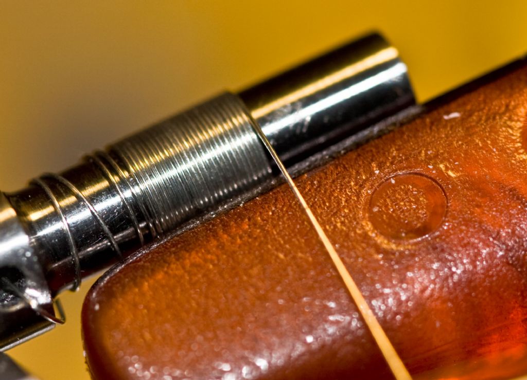 In getting close to completing each step of my skeleton clock, I believe that I owe several of you gentlemen a thank you and at least show my final method for making the balance spring. I must preface my notes by reviewing a few issues, and to intersperse acknowledgments for the ideas of others who helped me to reach what I believe is a viable solution. Background I have already mentioned in previous discussions that the helical spring in my John Stevens skeleton clock was originally intended to be a rectangular cross-section from wire 0.020" x 0.005" (I will stay in Imperial units for this exercise). It can be appreciated that a spring wound from wire with a rectangular cross-section offers lots of vertical stiffness, while remaining far less rigid in the direction it will bend in use. For a wide range of reasons, too numerous to list here, I elected to recalculate the stiffness in terms of round wire. This was a simple exercise to determine the equivalent stiffness (moment of inertia) in my CAD package. A wire 0.008" in diameter was the result. Where to get this size of wire? Someone suggested guitar strings, and I was lucky enough to discover from a friend who owns a music shop, that this was the smallest string normally available over the counter. Such luck! The finished sizes of the helical spring were to be 3/8" OD and nine turns to produce a working length of about 3/8". Had I still retained my Myford and other workshop machinery, I could have set the pitch accurately and wound the spring with the pitch built into the winding process. I would also have guided the wire onto the mandrel as was also recommended in various places and by the kind thoughts of other contributors. However, I had borrowed a lathe which was not very attractive in the screw-cutting department, and therefore elected to close-coil the wire. In other words, the wire would be touching itself on each successive rotation of the mandrel. I have also to say here, and as was explained to me some time ago, the wire is itself, caused to twist on its axis during the process of winding. I have no idea how this manifests itself, so I chose to ignore it other than to allow the wire to have the maximum amount of freedom as winding took place. Winding tests showed that a 5/32" steel mandrel would, when the wire was cut free, produce the requisite spring OD of 3/8". Up until now, I had turned the power off to the lathe, and only turned the three-jaw chuck (backwards) by hand. Very tedious, but also fairly safe. Unlike running under power which is not recommended. Controlling how the wire was held in place on the mandrel both during the winding stage, and before being released, had already been discussed elsewhere and amounted to applying pressure to the coils with a fixed piece of soft wood and running this with the lead-screw feed set to the spring pitch. My efforts were abysmal.  I couldn’t control the coils which would wrap themselves together in an unglorified tangle. I was also drawing attention from SWAMBO, who had begun to notice how much time I was spending in the music shop, and how much housekeeping was going on emptying the music shop of guitar strings. So I needed another method of stopping the coils flying apart uncontrollably once I had made that necessary cut. Method Before explaining my technique, it is essential that you take great care to avoid accidents. WINDING SPRINGS CAN CAUSE SERIOUS INJURY.
Using 0.008" diameter guitar strings, which are about 39" long, I ran a weighted nylon thread over a pulley for more than this length so that the guitar string had plenty of freedom to twist on its axis should that be taking place. My weight was a convenient drill chuck off the lathe, and weighed about 1/4 lb. The next tricky bit was threading the guitar string through a tiny hole drilled across the mandrel, sharp edges removed, and then rotating the lathe chuck until the end of the wire was caught and secure. The position of this hole in earlier attempts (with the hole drilled into the adjacent larger diameter of the mandrel) had, I believe, introduced some addition twisting into the wire as the wire slid briefly down onto the working diameter of the mandrel. The nylon thread (with weight attached), and the wire are suitably connected, and the winding process can begin. I also took great care to avoid kinking the wire in any way. Clearly, this would affect the desired outcome. While I am certainly not recommending driving the chuck under power, I was running out of time, patience, guitar strings, and the need to avoid getting cramp in my old hands. I calculated that the winding time under power would be about 15 seconds, so I set the lathe in reverse (it has a bolt-on chuck so would not unscrew), and standing well clear, I turned on the power. It worked like a charm.
 But I still had to stop the coils from spinning off the mandrel. It was then that I hit on the rather ludicrous idea of gluing the wire to the mandrel. Having noted on many an occasion that clock and watch makers use shellac as a glue, I pasted some of my own concoction over the coils, hoping that I could later soak the glue and the wire in meths and trusting that the coils would uncoil themselves slowly and under control. It failed!
The shellac had not f |
| 17/06/2011 01:26:02 |
Hi Pat,
Your comments about the springs in moving-coil meters are most interesting. I too, found that the end `finishes' were important in getting my springs to work properly.
Although there is some angular variation with my clock's balance wheel, I estimate that while the clock is ticking away, the total angular displacement is as much as 450 degrees of arc.
I suspect that variations in the angle of swing, relate to things like the fusee geometry, my rather crude gears, maybe the bi-metallic aspects of the balance wheel, and dare I say it - the condition of the main spring. I'm now concentrating on building a suitable case with a fabricated glass cover.
Also, thank you for your compliments.
Best regards,
Sam |
| Thread: A plastic valve |
| 15/06/2011 09:44:34 |
|
Thanks for your comments Michael. I agree with you about fluidics, and how it doesn’t seem to have established a place in technology. For companies into pneumatics, it was probably attractive in the early days, but I would assume that there are many more electronic switching solutions rather than adopting this method. I've seen (on TV) the results of using air lines to trigger lightening strikes through copper wire, but I imagine even this would not need sophisticated fluidics. I was rather fortunate in developing and succeeding with the plastics valve. Developing from a simple conversation with a friend in research, I went on to make quite a range of specialised laboratory equipment.
This `arm’ of my business was (for a while at least), becoming bigger than my involvement in plastics technology.
Regards, Sam |
| Thread: Super Glue & Balance Springs |
| 15/06/2011 09:12:42 |
Thanks Clive,
That's a super (glue) solution.
Since my clock is now working, I'm no longer in need of making more balance springs. I actually came close to emptying the music shop of their stock of their thinnest guitar strings.
However, I feel sure that your comments will serve to provide a neat answer should anyone care to develop this spring-making idea still further.
Thanks for your help.
Regards,
Sam |
| 15/06/2011 00:34:29 |
|
When I introduced the thread about near empty tubes of super glue, and although it was a significant irritation at being ripped off, I was actually in the middle of some final experiments to make a usable balance spring for my skeleton clock. In previous threads about balance springs, I searched and tested several ideas to try to find (with my limited equipment), a reliable method. As my own notes show, I had determined that a wire diameter of 0.2mm (0.008") would replace the flat section as used in the original clock design. This has since proved to be fairly accurate since the clock is now beating with an accuracy of less than 1 sec/hour, and responds well to fine adjustments. That said, I can briefly describe my approach to making my balance springs. The most significant problem I have had when winding the spring onto a 4.0mm diameter mandrel has been how to uncoil it successfully after winding. Once released, the usual result has been for the spring to fly open and to wrap itself into an unuseable mess. There have been some very useful comments posted, some of which pointed to additional twisting which takes place (unseen) during the winding process. Michael Williams wrote :- The traditional method of making very small springs with limited equipment is to pass the feed wire through a hole in a piece of flat soft wood and arrange for the flat part of the wood to bear down on the coils that you have already made . Until such time as you deliberately remove the wood the coil remains tight and under total control . You cut off surplus feed wire with the wood still in place and then slowly lift it away . As an added bonus there is an element of screw-cutting going on in the wood and after a few turns; a neat set of grooves form which help to keep the winding pitch constant . Please be very careful when winding springs under power - it is a terribly dangerous process. Perhaps it was the hidden twist and how I anchored both ends of the wire which were responsible. To avoid weakening the mandrel I had drilled the 1mm anchor hole through the larger 1/4" diameter section. What seemed to be happening was that the wire was skidding down the side of the step, thus introducing extra twist. This was rectified in my final attempts. The free end was weighted and the wire was passed over a simple pulley. I took the trouble to stop the weight from spinning, expecting that any back and forth twisting would be transferred to the spring. Taking note of all the warnings, winding the wire onto the mandrel had always been done by hand with the main power switch turned off. This was very tedious and tiring for my old hands and fingers, since reaching the three-jaw was awkward. I had also chosen to wind the spring ACW so that I could see a little more of what was happening to the winding process. It was at that point that I decided to wind the wire under power with the lowest lathe speed (267 rpm), and in reverse. The chuck was bolted so there was never any danger from it unscrewing. I also calculated that I had at least 15 seconds before I had wound all of the 1 metre length of guitar string onto the mandrel. I stood ready to switch off, and hey presto, a nicely wound spring. That was until I removed the wood which Michael had suggested. Another tangled mess! That was when I went off at a tangent, and began to explore the possibility of gluing the wire to the mandrel, and using a solvent to let the spring slowly uncoil. The traditional `glue’ in clock making is shellac which dissolves in methylated sprits. This would be ideal, or so I thought. So I tried again giving the tightly wound wire a good coating of shellac, waiting overnight for it to set. It didn’t work so I figured that the shellac had not found its way under the wire and onto the mandrel. With that fixed, I tried again. The wire instantly flew into another mess, and another guitar string went into the bin. I interpreted this result to mean that the shellac was too brittle, and/or hadn’t bonded sufficiently. It was also possible that the meths had not fully evaporated completely from under the coils. That’s where the super glue came into the picture. I should (again) point out that super glue (cyanoacrylate) sets by combining with moisture from the atmosphere or from your breath. It is also supposed to soften in acetone, which would be ideal, or so I thought. With a very thin coating of super glue applied to the surface of the mandrel, I tried once more, applying two coats to the tightly wound coils. Several hours later, I cut the wire. Whoops!
The wire uncoiled but didn’t tangle. But the freed wire was stuck together over much of the length of the spring, albeit at about the correct spring diameter of 9mm. I had my bottle of acetone (nail-polish remover) ready, and promptly dropped the spring into it. Nothing seemed to be happening. The coils remained stuck together, and the acetone seemed to be doing nothing either.
When I fished the spring from the acetone, it became clear that although the glue had turned white(ish) it was still present. Very carefully, I teased the coils free, and found that I had to strip off whiskery lengths of glue still attached to the wire. Remember, the diameter of the wire is only 0.008". This posting may provide food for thought, but it has become more of a saga, so I must end here. One question. Why didn’t the glue dissolve in the nail-polish remover? |
| Thread: A plastic valve |
| 14/06/2011 05:50:21 |
|
Gentlemen, In response to a couple of questions about my de-burring technique, especially from Pekka, I cobbled together a couple of schematics from what I remember. It was, after all about 30 years ago. Michael Williams has reminded me also about the fluidics phenomenon, which I seem to recall involved Enots. However, I hadn’t realised that the valves mentioned could cope with liquids besides air.
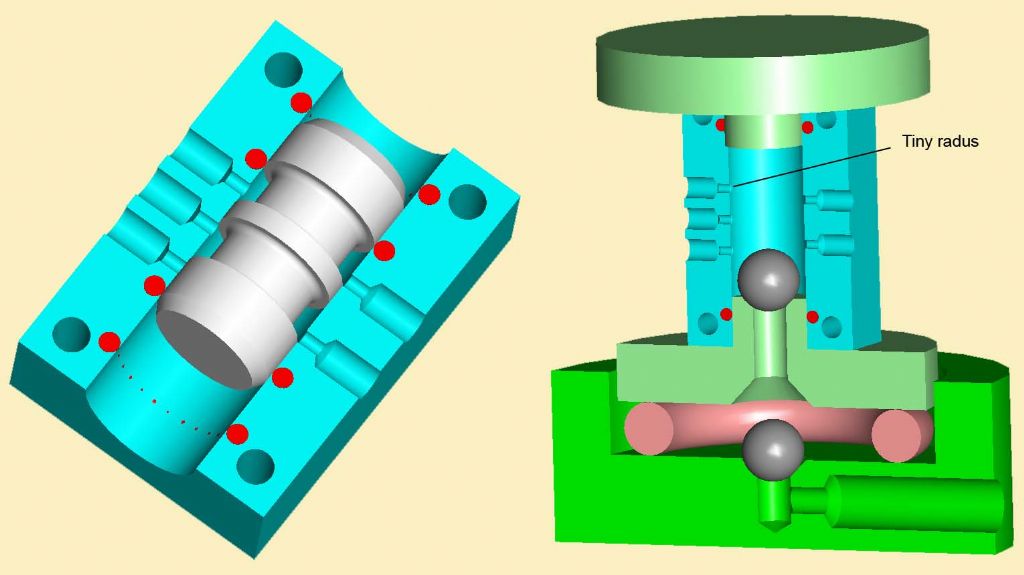 In my diagrams, you can see the basics of the valve, and the method I used to pump the tripoli slurry through the valve ports. The slurry was gravity fed into the bottom RH drilling, while the two balls controlled the direction of flow. However, while there are a couple of notes with this picture, I hesitate to go into specific detail unless anyone has additional questions.
Regards to all,
Sam
PS My skeleton clock is now running well with previous over-night errors of about 2 seconds per hour fast. After todays adjustment, the last (three-hour) time check, revealed an error which was too small to record against my computer clock. Edited By Sam Stones on 14/06/2011 06:03:21 |
| 10/06/2011 04:52:29 |
|
This posting could be titled - How I de-burred the tiny holes in the PMM valve bodies. Just to back-track a moment, the inside bore of the PMM valves had a honed and highly polished finish. That was eventually my minimum standard. Where the five 1.0mm holes broke through however, the best result was a sharp corner, while the worst was a burr. Clearly, the PTFE spool would be damaged if this condition prevailed. The solution was quite a simple idea really, and one which Pekka alluded to in his earlier posting above. The solution - Use a particulate slurry, and flush this backwards through the holes.
But, what sort of equipment should I use to achieve this? What sort of particulate material would be most suitable?
I settled on tripoli as the preferred powder, and I presumed it was the same stuff found in liquid metal polish. It was cheap and could be mixed with water, so the PMM was safe from solvents. I added a very small amount of wetting agent to help to disperse the powder in the water, while avoiding a severe dose of the froths. The mechanism was fairly simple too. I had an old washing machine motor and added a large ball race to the shaft with about 5mm eccentricity. This eccentricity was to produce my up and down movement. A couple of polypropylene (PP) adaptors suitably spigoted to locate into the bore of the valve body closed off the bore, one of which was drilled through to allow the slurry to pass. A simple ball valve sitting inside the bottom adaptor ensured a reasonable one-way flow of slurry. A stubby length of RPVC about 40mm diameter formed the body of the contraption, while providing a miniature priming tank for containing the slurry. The tricky bit was still to come, ie. how to make the pumping action take place without too much leakage? As I recall, this came in the form of a couple of rather chunky `O’ rings roughly the same diameter as the RPVC tube and about 6mm in cross section. Besides helping to form a seal between the tank and the outside world, there was sufficient `give’ in the `O’ rings and the rest of the contraption for the eccentric ball race to generate a pumping action. In other words, to squash the assembly up and down, forcing the slurry through the tiny holes. Fifteen minutes of this while I carried on with something else, and the job was done. It took a low power microscope to view the beautiful radii which had replaced the burrs and sharp edges on these largely inaccessible places. Although I’ve searched amongst my old samples to provide a picture, it would appear that they have all been dumped during successive moves. Regards, Sam |
| 10/06/2011 01:23:19 |
|
Gentlemen, Thank you for your compliments, I’m only pleased to have somewhere to divulge some of my `tricks’. Before I disclose my method of de-burring the 1.0mm holes into the body of the PMM (Perspex) valves, I need to make a couple of comments about the more recent postings. I fully agree with Pekka regarding the machining and use of unfilled PTFE (Teflon). However, once its basic properties like creep, coefficient of friction, and inertness are understood, these can be dealt with as required. Pekka, your comments have aroused my curiosity. I suspect that you have worked in a research environment where these valves (or similar) were in use. I designed them specifically for one task in a biological research laboratory. From your other comments, I have to say that I also developed and made several other pieces of laboratory equipment, none the least being an infusion pump which would physically accept standard syringes from 5ml to 50 ml. Stepper motors were indeed used as the motive force, while the engagement and re-setting of the pump and syringe was achieved using a gearing-down lead-screw system not unlike a lathe split-nut arrangement. As I recall, with a wide range of speeds and syringes, discharge amounts could range from a millilitre or two over several hours, through to a relatively quick discharge of 50ml in just a few minutes. Another very serious semi-production task I developed, also involved machining elastomers. This was where the kitchen freezer became an import part of the equipment. It was of course, necessary to push the frozen food to one side, to make room for the items to be `frozen’. Around the mid 80's, both of my kids were heavily into roller skating, and the polyurethane wheels would wear unevenly. Over a number of weekends, a semi-production line began to evolve as more and more kids asked for their wheels to be machined.
I found that a wheel reduced in temperature to between minus 15C and minus 20C could be brought back into service to an acceptable `standard’ rather quickly. Setting the lathe feed to about 20tpi produced a grooved finish which the kids loved and presumably bragged about. The single point tool was given a very steep top rake similar to that which I would use for aluminium. A hidden benefit to this operation was that a slight amount of condensation developed on the wheels which seemed to improve the so-called cutting action. In hindsight, slicing rather than cutting would better describe this action.
Coping with the high `discharge’ rate of the polyurethane swarf was perhaps the hardest part of this production line, until my son and I decided to let the swarf wrap itself around the wheels and remove it later. A sharp Stanley knife worked wonders. As for the PTFE spools, and to pick up on the comments from Pat, Hansrudolf, and Andrew. Using the 1ml syringes as the `power’ source as mentioned before, the spool was caused to slide a mere 2mm, so that either one of two fluids could be switched rapidly as they were directed into the specimen bath. A material combination with minimal stick-friction was required. The best materials I had access to, and which were suitable for my modest home workshop were polymethyl methacrylate (PMM - better known as Perspex), and polytetrafluoroethylene (PTFE - better known as Teflon). Together, and with the degree of fit I had determined as suitable, these two materials produced virtually no stick friction, and provided a positive seal between the adjacent fluid channels. Since you asked Hansrudolf, all of my work in making these valves was carried out on my Myford ML7, and a nerve-wracking Chinese mill/drill. It wasn’t (and dare I suggest still isn’t), possible to use a micrometer to measure the central diameter of the spools to the level of accuracy I found necessary, especially since this middle section (web) of the spool was only 1.5mm wide. At this scale, PTFE is too soft and slippery to get any kind of sensible reading. What I did was to use Go/NoGo gauging and selective assembly. For repeatability, the Myford was good enough for me to leave the cross-slide locked, and make final surfacing cuts without disturbing anything but the saddle. Getting back to the original Thread, and why de-burring was so important. The minimal interference fit of the central section of the spool and the valve body, was still such as to cause the PTFE to (dare I say) exude into the 1mm port holes. Therefore, any kind of sharp edge was likely to interfere with, and even shear off, a tiny sliver of PTFE from the spool. Since some of the research involved measured millivolts, any liquid bridging the central spool web was likely to interfere with these low voltage measurements. This posting has growed like Topsy, so I’ll add another posting to describe how I de-burred the holes. Regards to all, Sam |
| 09/06/2011 00:55:10 |
|
I intend to hold off a little longer before explaining my de-burring method wrt drilling 1.0mm holes through PMM. Hints at my method have already appeared.
Instead, I shall put some comments forward in response to the above replies.
To obtain a positive seal between the inside of the PMM and the PTFE spool, while bearing in mind that PTFE does creep, I made the centre section of the PTFE spools a small amount larger in diameter, ie. about 0.008mm (0.0003"). This was all I was prepared to trust from my lathe in a semi-production sense. The unfilled PTFE was ideal in terms of its low friction characteristics, especially that of `stick’ friction. Both materials (PTFE and PMM) had to be relatively inert to the fluids being processed. In response to PekkaNF’s comments about machining PTFE, it's a material which is not easy to grip. Unlike POM (polyacetal, Delrin,) which is more rigid, and swarf normally comes away cleanly (unless static builds up and pulls the swarf onto the workpiece), unfilled PTFE is soft and slippery. Its creep resistance is very low too, so it becomes necessary to surround the workpiece with metal as a means of reducing movement (creep). At the time, I had quick release collets, so gripping the PTFE bar-stock was not an issue. Another aspect which came to my notice in terms of the performance of the valve, was that at 19 degrees C, PTFE goes through a phase change and sharply increases in volume. This had to be taken into consideration for valves specified for use in applications where the operating temperatures were above 0 degs C, but below 19 degs C. For these special lower temperature versions, I made the diameter of the PTFE spools a small amount larger to accommodate this drop in volume. I also had to supply special instructions for when the valve was not in use. Researchers could either keep the valves in the fridge or strip them down to remove the spool. Storing the separate parts at room temperature was not a problem, although an important part of preparation for use was to reduce their temperature to below 19 degrees, and to keep them below 19C while in use. Returning to de-burring, I think Weldsol’s comments about using a sacrificial bar has merit, although I needed to make quite a few of these valves, so it would be necessary to jig the bar to accurately locate the hole centres and avoid significant (bar) wastage. This wouldn’t have been too much of an issue since I was already drilling the holes with a drilling jig. However, I do wonder about what would happen if the drill wandered slightly. Colin - I’ve just returned Sparey’s book to the library, (after reading about his method for winding helical springs). However, his comments about `... drilling Ebonite, Bakelite and other plastics ...’ reminded me that drill-pointing to a very steep angle was the method being used in the plastics factory where I started my apprenticeship in 1950.
There were very few thermoplastics in those days, so melting was not a real issue. These days, we are inundated with a huge variety of mainly thermoplastics. As it happens, before I started my own business, I was a technical officer servicing polypropylene (PP). One of this material’s characteristics is its ability to be hinged. The so called "Living Hinge".
When machining PP (which begins to soften at about 130 degs C and melts quite sharply at about 175 degs C), this hinging property is also responsible for producing very ragged edges.
It doesn't want to let go!
 The best results with most thermoplastics appears to be having very sharp cutters like woodworking tools, lots of swarf clearance, and reducing the cutting speed.
Keeping the work wet will help to reduce the heat build up. I could go on about PP but that’s another story.
Regards to all,
Sam
Edited By Sam Stones on 09/06/2011 01:02:22
I've just remembered. I arranged the spool to be pushed back and forth hydraulically. The source of this hydraulic `power' was via two 1 ml hyper-dermic syringes. Edited By Sam Stones on 09/06/2011 01:06:49 |
| 07/06/2011 07:58:51 |
|
Some considerable time ago, and quite by chance, I found myself designing and making a miniature five-ported hydraulic valve for use in medical research. It was machined from solid Perspex (PMM) and measured about 26mm long by 22mm wide by 16mm deep. It was to be secured to a microscope stage operating at fairly high magnification, and hence had to be remotely controlled to avoid generating vibration. I chose to make the spool from Teflon (PTFE), which had to seal completely, two fluids being switched by the valve as the fluids passed through it. In other words, there must be no leakage. The main bore of about 9mm diameter had to be machined and reamed with the minimal amount of frictional heat, so that final lapping (essential for accuracy and finish), didn’t cause crazing. Some liquids can be seen to induce stress-cracking from inbuilt stress, (a bit like happens when a high density polyethylene injection moulding comes into contact with detergent solutions). This crazing of the PMM was initially found to be a significant setback, until I developed a satisfactory low heat machining solution. However, the real problem came when drilling the five 1.0mm port holes. As these broke through into the 9mm bore, you would expect a significant burr to be formed on the inside.
There was. Five of them.
The action of shunting the PTFE spool over this rough surface would immediately damage the spool and defeat the purpose of the valve.
Once the word got out, I finished up making and selling several dozen of these individually manufactured valves to various research groups around the world. My question is :- How would you deal with the burrs?
I'll post my method in a few days.
Sam |
| Thread: Is it abuse if I...........? |
| 07/06/2011 01:47:13 |
|
To answer Nobby’s question, there are several 12BA screws in my skeleton clock. They hold the hardened end (thrust) plates in position for the bottom bearing of the balance wheel arbor, and the bottom bearings of the two escapement arbors. Having said that, and this is about tapping and the use of tap wrenches, I have to admit that under these circumstances, I twirled the taps in and out between my finger and thumb. AND, I was only tapping into brass. It’s nearly forty years ago so I can’t remember exactly, but I may have assessed the resisting torque versus the tap’s strength together with the squeak coming from the brass/tap, to know when to back off. If we are talking about screw size, my ego is quickly deflated when I peer inside an old watch. Regards, Sam |
| Thread: Super glue (cyanoacrylate) |
| 06/06/2011 05:40:32 |
|
Hello Dick, Thanks for your post.
I have to say that it was my initial gripe about being ripped off when buying Super Glue, that set me going on this thread.
The delicacy of making the balance spring in my clock is such that I would find using a hot melt adhesive a bit too risky, but thanks for the thought. In the meantime, and despite taking an inordinate amount of time, I was largely successful in making a suitable clock spring from 0.2mm guitar string wire. I will probably open a thread about it shortly. My method only took about two drops of super-glue to achieve what I was after.
Regards,
Sam |
| 04/06/2011 00:41:09 |
Hi Terry,
I agree, and clearly remember asking a retailer why the bottle of Loctite I had just bought was half empty. On that occasion, I didn't get a technical answer, except "They're all like that!" He exchanged it and gave me another bottle also half full - or was it half empty?
My gripe is that the tube of Super Glue clearly states NET 3g but, as my picture shows, the tube certainly contains less than one gram.
Isn't this fraud?
Unlike (normal) Loctite which sets from the exclusion of oxygen, it is my understanding that cyanoacrylate begins to set from the adsorption of moisture from the atmosphere. If you want it to set quickly, you simply breath on it. As you do, you will see it turn white.
While I was really voicing my annoyance at the Super-glue rip-off, this thread is beginning to become a storm in a teacup. One or two drops of glue was all I needed.
What I'm actually trying to do is find the best temporary adhesive which will hold my helical clock-spring onto the winding arbor, and so that I can control its unwrapping action. My previous attempts with 0.2mm (0.008") wire, both dry and using shellac have resulted in a twisted, tangled mess.
In an hour or so, I shall know if super glue (dunked in acetone) is the way to go.
By the way, I'm getting some strange looks from retailers, because my recent purchases have been for eyebrow tweezers and nail-polish remover.
 Ah! The ways of clock making. Sam |
| 03/06/2011 05:39:20 |
|
Great stuff this Super Glue (cyanoacrylate), but is it just me or do others get ripped off when buying it. The regular, off-the-shelf tubes of glue are marked NET 3g (three grams), but how coarse is the NET? Time and again when I buy a tube of this stuff, the tube certainly does not contain 3 grams of liquid. OK, so with a density of 1.1 g/cm3, the tube would contain less than 3 cubic centimetres. But take a look at the photograph which compares a full tube with one which I squeezed until the air was expelled. Admittedly, I was in the middle of a job and couldn’t stop before using about two drops prior to re-capping the tube. I also have to accept that some of the glue is lost in filling the nozzle, but what happened to the rest?
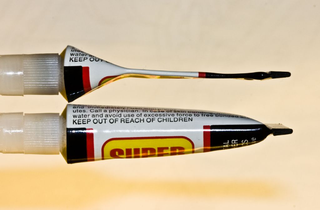
I once challenged the suppliers of 3g tubes in a brief run of emails, and was quite taken by their total contradiction. Initially they claimed that apart from the occasional empty tube, their QC was such that every tube was filled completely. In a subsequent email, it was stated that sufficient space had to be allowed in the tube so that the glue could be squeezed out safely.
Am I just a cheap-skate, or does anyone else share my views?
Sam |
| Thread: More clock stuff |
| 01/06/2011 01:38:17 |
|
Hi Stephen, Dick, and Norman, Thanks for your comments about using ball races, and about handling the main spring. Given more time and a proper workshop, I would be very tempted to fit ball races into the clock. If you know of Rex Swensen (Sydney, Australia), he is a strong advocate of fitting them into clocks, and has offered several important engineering ideas to support his work. His notes can be seen in another forum. As for removing the main spring, I can only offer the following comments. Your word `gripe’ Dick, certainly describes the brief whirling sound the spring makes, as it unblocks itself. I had thought that this would have been fixed with oil!? When I bought it from Messrs E E Gray of Clerkenwell, a London supplier back in the 70's, I simply inserted it (halfway) into the barrel before cutting it free from the wire binding. That’s where it has been ever since, and has never been unwound. At this point in time, I would not be able to tackle the exercise of removing it alone. Perhaps I should take it to a clock maker who should have a spring winder? As a general warning to anyone who doesn’t know, there is still a lot of `power’ left in a spring of this kind. I understand that some of this power is often produced by the spring being initially manufactured with a partial curve in the opposite direction to the way it is eventually coiled in use. I’m also left wondering what lubricant would best suit this situation, and for long term use. I know of lubricants containing a suspension of micro-fine PTFE (Teflon) particles. Would this be a better bet? Thanks again, Sam |
| 31/05/2011 03:15:50 |
| Gentlemen,
Although my skeleton clock has been running for many hours, there have been one or two occasions when it has stopped for no obvious reason. There have also been occasions when there is an abrupt rumble coming from the main spring. Although not clearly visible in this picture, for an idea of spring size, this barrel is about 60mm diameter, and 50mm wide. 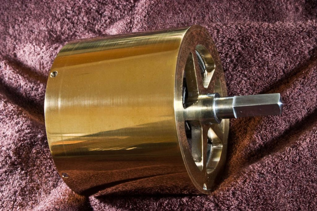 There is ample sideways clearance for the spring inside the barrel. I conclude that the main spring is sticking to itself thus holding back the necessary driving torque. A sort of stick-friction, or perhaps capillary action.
In the initial `start-up’ a couple of weeks ago, I ran some sewing-machine oil onto the edges of the spring, and now wonder if the spring should be lubricated or washed in petrol and left relatively dry.
There is also the possibility that over the 30 or so years the clock stood around, parts of the spring rusted.
What are your thoughts?
Sam |
| Thread: My skeleton clock |
| 26/05/2011 05:24:23 |
|
Hello you clock-watchers,
In case you are following my very slow progress, I have added three more pictures to my album - John Stevens Skeleton Clock Part 1. There are now 30 pictures in this album.
The new pictures show the three essential elements which are a part of the skeleton clock `coming alive’. The fusee and barrel can be seen connected together via an 80lb (36kg) breaking strength braided fishing line. It was a nice stroke of luck that the line was yellow. It seems to go well with the brass. During winding, the line is transferred (upwards) from the barrel to the fusee at a decreasing rate, thus providing a type of torque compensation as the main spring approaches being fully wound. I’m not convinced that the profile of the fusee, generated by a 2" radius, accurately compensates for the increasing main-spring torque. But it’s going to have to do, cos I won’t be making another. However, while I was winding it up completely for the first time, I could feel the compensation taking place. Also visible in this picture, although not easy to determine, is the stop-work mechanism designed to prevent over winding, and thus avoiding having the line drop off the end of the fusee. It is identified by the notched steel arm pointing away from the camera. As the line is wound onto the fusee and travels towards the front of the clock, the spring-loaded steel arm is deflected into alignment with the snail-shaped hook, just visible under the small end of the fusee. Although concealed within the `great wheel’, there is a blued-steel circlip-shaped spring called the maintaining spring. This provides continuing power to the clock during winding. While it is not obvious, there are 29 items (including screws) which make up the entire fusee mechanism. The next picture shows each of the important parts of the escapement. I deliberately chose a long exposure time to display the movement of the escapement. Hence the reason for the blurred image. There are already pictures in this album showing this part of the clock before the clock came to life. The oscillation of the lever is just visible as a double image above the fifteen-toothed ‘scape wheel. At the top of the picture is the over-stiff spring, responsible for the fast beat. It is made from 0.011" (0.28mm) diameter wire, whereas my calculations suggest it should be 0.008" (0.2mm) diameter. Other calculations reveal that this thicker wire produces a spring which is approximately twice as stiff as it should be. My last picture to be added shows the bell and hammer in place. This `once-on-the-hour’ strike is just about to take place in the picture. However, because the clock is running at more than twice the correct speed, it currently strikes every 28 minutes. The hammer is lifted via a pin on the `minute’ wheel and `lifting piece’ positioned at the front of the clock. It was necessary to introduce a spring which would stop the hammer from bouncing more than once on the bell. This seems to work OK. The rough-looking screw just about the hammer head provides end adjustment for the `fourth’ wheel (contrate), who’s teeth are turn at right angles to engage with the 14 toothed escapement wheel pinion. I’m yet to go into the garage and make some more, softer, balance springs.
Regards to all,
Sam |
| Thread: turmning test |
| 23/05/2011 08:06:26 |
|
In my opinion, that sort of finish is typical of very low grade mild steel (MS), where the swarf is tearing and periodically reattaching itself to the workpiece. Someone gave me some old lift (elevator) 3" diameter winding axles, removed from a city office block in Melbourne. I was delighted until I came to use it. It turned out to be rubbish, and wouldn’t turn or mill without wearing out cutters. With reference to this thread, a test with the same cutters on some free-cutting MS might prove me wrong. And of course, having the cutter height set correctly if that wasn’t already checked. A decent cutting fluid might also yield more information.
Regards,
Sam |
Magazine Locator
Want the latest issue of Model Engineer or Model Engineers' Workshop? Use our magazine locator links to find your nearest stockist!
Sign up to our Newsletter
Sign up to our newsletter and get a free digital issue.
You can unsubscribe at anytime. View our privacy policy at www.mortons.co.uk/privacy
Latest Forum Posts
- hemingway ball turner
04/07/2025 14:40:26 - *Oct 2023: FORUM MIGRATION TIMELINE*
05/10/2023 07:57:11 - Making ER11 collet chuck
05/10/2023 07:56:24 - What did you do today? 2023
05/10/2023 07:25:01 - Orrery
05/10/2023 06:00:41 - Wera hand-tools
05/10/2023 05:47:07 - New member
05/10/2023 04:40:11 - Problems with external pot on at1 vfd
05/10/2023 00:06:32 - Drain plug
04/10/2023 23:36:17 - digi phase converter for 10 machines.....
04/10/2023 23:13:48 - More Latest Posts...
- View All Topics
Support Our Partners


Shopping Partners
Subscription Offer

Latest "For Sale" Ads
- Reeves** - Rebuilt Royal Scot by Martin Evans
by John Broughton
£300.00 - BRITANNIA 5" GAUGE James Perrier
by Jon Seabright 1
£2,500.00 - Drill Grinder - for restoration
by Nigel Graham 2
£0.00 - WARCO WM18 MILLING MACHINE
by Alex Chudley
£1,200.00 - MYFORD SUPER 7 LATHE
by Alex Chudley
£2,000.00 - More "For Sale" Ads...
Latest "Wanted" Ads
- D1-3 backplate
by Michael Horley
Price Not Specified - fixed steady for a Colchester bantam mark1 800
by George Jervis
Price Not Specified - lbsc pansy
by JACK SIDEBOTHAM
Price Not Specified - Pratt Burnerd multifit chuck key.
by Tim Riome
Price Not Specified - BANDSAW BLADE WELDER
by HUGH
Price Not Specified - More "Wanted" Ads...
Get In Touch!
Do you want to contact the Model Engineer and Model Engineers' Workshop team?
You can contact us by phone, mail or email about the magazines including becoming a contributor, submitting reader's letters or making queries about articles. You can also get in touch about this website, advertising or other general issues.
Click THIS LINK for full contact details.
For subscription issues please see THIS LINK.
Digital Back Issues


Donate

 Register
 Log-in
Model Engineer Magazine
- Percival Marshall
- M.E. History
- LittleLEC
- M.E. Clock

ME Workshop
- An Adcock
- & Shipley
- Horizontal
- Mill

Subscribe Now
- Great savings
- Delivered to your door

Pre-order your copy!
- Delivered to your doorstep!
- Free UK delivery!