Member postings for Stub Mandrel
Here is a list of all the postings Stub Mandrel has made in our forums. Click on a thread name to jump to the thread.
| Thread: Stuart Turner Sun Engine |
| 06/02/2010 21:53:28 |
Hi Alan, Not the voice of experience here, but I recall seeing a similar closed sump steam engine that used 'oil flingers', these are fingers that stick down from the base of the big end and 'fling' the oil where it's needed. It means you can use less oil and the big ends don't foam the oil so much. But it does require some work and a sump that clears the big ends by a fair margin. Neil |
| Thread: Is it worth the money |
| 01/02/2010 22:26:45 |
It's a darn sight better than my attempt at boiler making, and mine's a simple verticle one with a flue and cross tubes. Neil W. |
| Thread: Tachometer design |
| 01/02/2010 22:06:25 |
Thanks Les, Glad you took my post in the spirit intended. I'm not familiar with PICs and their architecture, but I can apprecaite the pin issue - driving displays eats output pins! Why not look at hall effect switches? They contain a schmitt trigger and all conditionng circuitry, all you need is a +3 to +30v supply, and a pull up to Vdd on the output: http://uk.farnell.com/allegro-microsystems/a1104eua-t/hall-effect-switch-sip-3/dp/1521705 I find one of these 100% reliable. Neil |
| 31/01/2010 21:01:11 |
First: I'd like to see Les get his article published and then we can stand well back and see what happens! Most micros these days have bult in comparators that will do the job as well as or better than an LM393, though a sensor (opto or hall effect) with built in conditioning is the most reliable solution. Many micros have serial ports that can easily speak to a PC, just add a MAX232 or similar to get the right levels, or even a USB-RS232 convertor to allow USB connection. The problem with a PC link is getting the PC to do something with the data. Can I plug BBC Basic for Windows by from Richard Russell - the best £30 i ever spent on computing related stuff. If you used to play with home computers years ago, then this will allow you to do all your old tricks and use windows interfaces without the pain and anguish of Visual BASIC or similar. Neil |
| Thread: Nova |
| 25/01/2010 22:43:58 |
| That''s a really nice photo-set Ramon, and a very well a made engine at the end. |
| Thread: N.A. Subscriptions in Disarray |
| 25/01/2010 22:36:33 |
Posted by David Clark 1 on 25/01/2010 20:03:36: Hi There The posting above solves the problem why we changed subscription houses. EWA called in the administrators. Wish someone had told me earlier. regards David Ever feel like as mushroom? they keep us in teh dark and feed us b******t! Neil |
| Thread: Boring tools for Boring Head |
| 25/01/2010 22:34:15 |
I have some HSS boring tools that are somewhat like D-bits. Setting them is quite critical, as you need to angle them to get some top rake, whilst ensuring that the round undersurface doesn't rub. When the hole is near to the diameter of the cutter, it's best to arrange it with no top rake at all. You can add more as the hole opens out a bit, if required. the knack is to look very closely at the tool tip when it is stationary and touching the work. Check for point contact at the cutting edge, and no rubbing. It is a bit trial and error, but as you normally start with hole a lot smaller than finished size, you have plenty to practice on  The boring bit is opening the hole up a few thou at a time! |
| Thread: Milling Tools |
| 24/01/2010 22:30:17 |
LOL! A Stuart 10 which you can knock off in 3 or 4 longish evenings You might manage that! Mine took ages - It would take longer now as I'd try and do a better job. |
| Thread: Scale nuts and bolts |
| 24/01/2010 22:26:13 |
That's a very different modelling subject! Best of luck. The draughtman needs a haircut though! Neil |
| 23/01/2010 21:30:36 |
Hi Paul, You can lie awake at night worrying about this! I've found that the BA series really helps, because the 0.9-times step bewteen sizes means that there is always a size within 5% of the correct size. The thread scales with the size of the nuts, so it always looks right, even if it isn't scale pitch Many folk suggest that BA fixings with reduced size heads look best. The one pain in the neck is that the 'one size smaller hexagon' BA fixings can be hard to track down, and don't seem to exist below 8BA with 9BA hex. Another reason for variation is that some suppliers can't get hold of proper BA hex stock, and use the nearest metric size instead. Interestingly, though, looking at some old engravings the full size BA hex scales pretty well. So my advice is use the nearest BA size and get a good nights rest! Neil Edited By Neil on 23/01/2010 21:33:01 |
| Thread: Tachometer design |
| 23/01/2010 21:20:20 |
Another thought. With AVRs it would be easy to design a standard "ME Module" with a range of IO ports and programmable over a simple serial link (or USB via an adapter module) by having what is called a "boot loader". If everyone putting together projects standardised on the same module, chips with the bootloader could be sold cheaply, and the programmes could be downloaded for free from here. With a suitable choice of chip, it would be possible to apply it to all sorts of applications - from clocks and tachos, through DRO readouts and stepper motor controllers, to brushless motor ESCs and process controllers. A standard design would cut costs to the quick, and make it very easy to develop collaborative projects. It's likely that many hobbysists would prefer to go the PIC route, but if there's interest in going AVR, I'm up for designing a module and bootloader system. |
| 23/01/2010 21:11:06 |
Out of interest, if people want a practical layout, how about the one I use for my mini-lathe and mill? It fits in this neat transparent blue box about 2" by 5". It uses a hall effect switch taht has three wires (ground, 5v and signal) and all that's onthe machine is the stationary sensor and a small but powerfull magnet, 5mm dia by 1.5mm thick, - separation distance not critical. The magnet is so powerful; it isn't even glued on! The photos are a bit grainy as I didn't use flash. The pics show the speed range this can cope with, and also showcase the greater than 100:1 speed range of a mini-lathe with roller bearings fitted (I never use the 'high' range it goes scary fast!).   |
| Thread: Machining a Cylinder from the Solid |
| 23/01/2010 20:17:55 |
Epilogue: Just in case you wondered, here is the finished engine. This would also be a good way to machine a pattern for castings. I have made a couple more cylinders, one less than an inch tall - its so neat I'm putting off building it into an engine 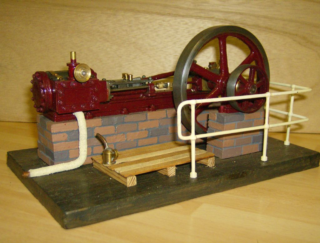 |
| 23/01/2010 20:15:21 |
| The final task at this stage was to drill the exhaust port, a less critical operation, as all I had to do is drill parallel to the valve face and avoid breaking into the cylinder bore. The only danger is breaking the drill as it emerges into the port. Now there it is, a cylinder complete, aside from drilling and tapping for the steam chest and end covers. While the process was rather more involved than machining a casting, it was far easier than I expected, largely because of the kind nature of the material used. So, if you decide to model a steam engine for which there are no suitable cylinder castings, have a go at milling one from the solid. 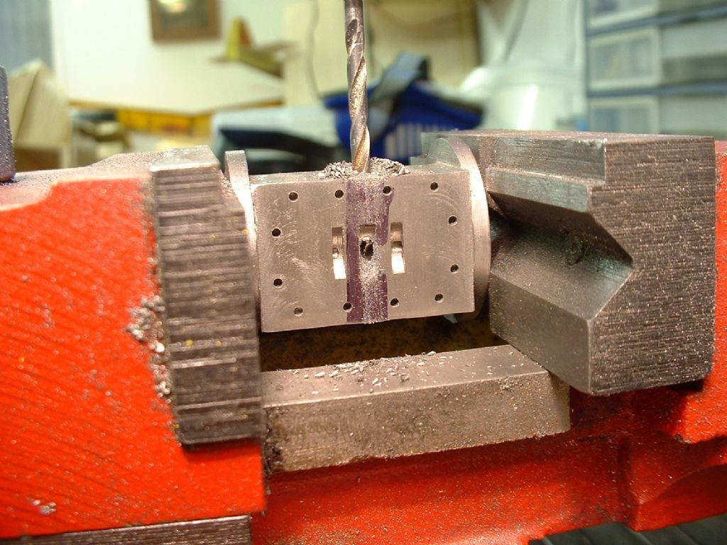 |
| 23/01/2010 20:14:00 |
| I used a milling vice to hold the cylinder (protected by aluminium slips) and used a 1/8" FC3 cutter to mill the 3/32" deep recesses at each end of the cylinder. I then used a tilting vice to hold it an angle to drill the steam passages number 53. I marked the position of the upper valve port on the side of the cylinder in pencil, and repeatedly moved the tip of the drill from in the recess to alongside the cylinder to ensure that it would break out into the port without damaging the face. It is essential that the drill neatly enters the corner of the recess for this to be successful. If you feed too fast or the drill is out of line when it starts, it will wander and could either snap, miss the port or, worst of all, emerge in the port face. I used a depth stop on the mill, and as you can see in the photograph, the drill neatly entered one side of the port. Without altering the angle of the vice I inverted the cylinder and drilled the other steam passage. This is a rather nerve-racking procedure. Try to err on the side of drilling at too shallow an angle, as if you miss the port you can ‘poke’ a 1/16" drill into the bottom of each port to link it to he passage. If you use an end mill to create your ports, you can make them a little deeper and the job becomes less critical - you can make a wooden 'cradle' to hold the cylinder for drilling as you won’t need to make small adjustments to the angle. 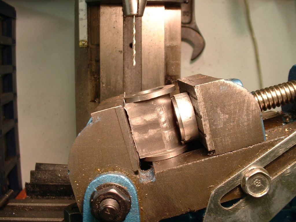 |
| 23/01/2010 20:11:46 |
| I clamped the cylinder to the milling table (you could equally clamp it to the vertical slide on a lathe), with the valve face perpendicular to the long axis of the table. I used an edge finder to locate one side of the valve face. This is a 'ball on a stick' which when spinning over a surface stays still, until they are precisely aligned, when it 'runs' along the surface. My ball is meant to be .250", but I miked it at .248”. A difference well worth being aware of if you are going to the bother of using such an aid to setting up! I advanced the cross slide by half the width of the valve face plus half the width of the ball. I now had to fiddle a bit to get the cutter exactly half way up the valve face, ensuring the chuck would clear the fixing bolt. I was very apprehensive that such a delicate looking cutter would bend or break if it dug into the work. With two sets of teeth in the work at once the total cut length would be 7/16", which is an awful lot for a tool shank about 3/16" in diameter. I ran the cutter at about 500 rpm, and fed the work into it very, very slowly. To my satisfaction, the swarf came out more like fine dust than chips, building into a neat cone beside the cylinder. The result was absolutely perfect, far better than I could have achieved with an end mill. It seems like the old guard knew a thing or two. 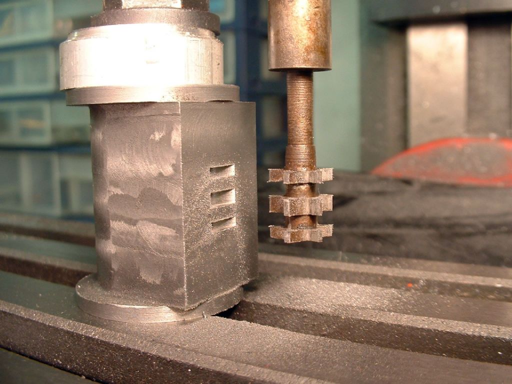 |
| 23/01/2010 20:10:23 |
I milled six teeth on the cutter following a sketch by Edgar Westbury in his M.E. series on ‘Unicorn’. This requires milling very large ‘bites’ with the cutter lined up on the centre line of the blank, in order to create pointed teeth with no top rake, and a very small witness at the tip. With the cutter running fast, but with a slow feed I had no problems with 'grab'. I indexed the blank by eye, as uneven tooth spacing is actually an advantage in this type of cutter, reducing the danger of resonant effects causing chatter. I carefully cleaned up the sides of the teeth with a file. I hardened the whole cutter then tempered it in the oven. I wanted to temper it a bit further than the usual pale straw, as it looked very fragile. I decided to start at gas mark seven (which is supposed to be about 220°/pale straw) knowing the oven thermostat was inaccurate by about one mark. This was just as well, as after a false start (my wife turned off the 'empty' oven), the cutter came out an even pale bronze colour that probably equates to dark straw. I used a diamond slip to clean up the sides of the teeth and to put a shine on the cutting faces. 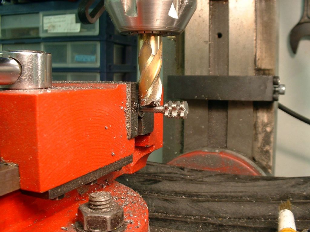 |
| 23/01/2010 20:08:19 |
| In theory I could have taken advantage of having the cylinder set concentrically to the bore and carried out other operations before parting it off the cast iron 'stick'. I decided not to do this as at this stage I had still not decided on details like the arrangement of cylinder cover studs, and I could only have drilled one end, anyway. From the sketch it was apparent that external dimensions of the valve chest would be about 3/8" deep and 1"long. The eccentric strap would be about 1/2" diameter. The width of the valve chest could not be deduced directly from the information I had, but the technique used for making the cylinder gave a width of just under 7/8". I had to decide on my own valve dimensions. I decided on steam port width and spacing of 1/16", exhaust port width of 3/32” and port length: 5/16". The ports can be milled out, but for guaranteed accuracy there is nothing to beat a simple ganged cutter as advocated by LBSC. A small diameter cutter is needed, in order to get a reasonable port depth. In this case to get a width of 5/16 and a depth of approximately 1/16" a cutter from 3/8" silver steel was chosen. Using a 1/16" wide parting tool I made a tool blank in the form of three disks on a shank. The end disks being 1/16" wide and the centre disk 3/32". The shank had to be long enough to clear the entire slide face and the top flange. |
| 23/01/2010 20:06:43 |
| The cylinder bore was given as 9", which scaled to 3/4" at 1:12 scale. This would have left the sides of the cylinder 1/16" thick at most. I felt this did not leave much of a margin for error or strength. The information also stated that this was an estimate, so I decided there was no reason why the bore could just as easily have been 8" on the original engine, and therefore bored the cylinder to 0.667". I used the half-center again and reduced the top flange to 3/16 thick, then took away all support and parted off the cylinder leaving the bottom flange the same thickness. It parted away leaving a small ring of metal attached to he end of the bore. This was so thin it broke off neatly under thumb pressure. I gently bevelled the cut edge with emery paper. 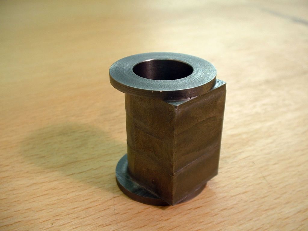 |
| 23/01/2010 20:02:58 |
I decide it would be sensible to drill and then bore the cylinder while it was set up accurately centred in the chuck. I went up using several drill sizes in order to avoid any risk of a drill jamming and spoiling the set up. Final boring was done dead slow with cutting oil and the tip of the boring tool stoned to a gentle curve. The reward was the lovely satin grey finish that is ideal for a steam cylinder. 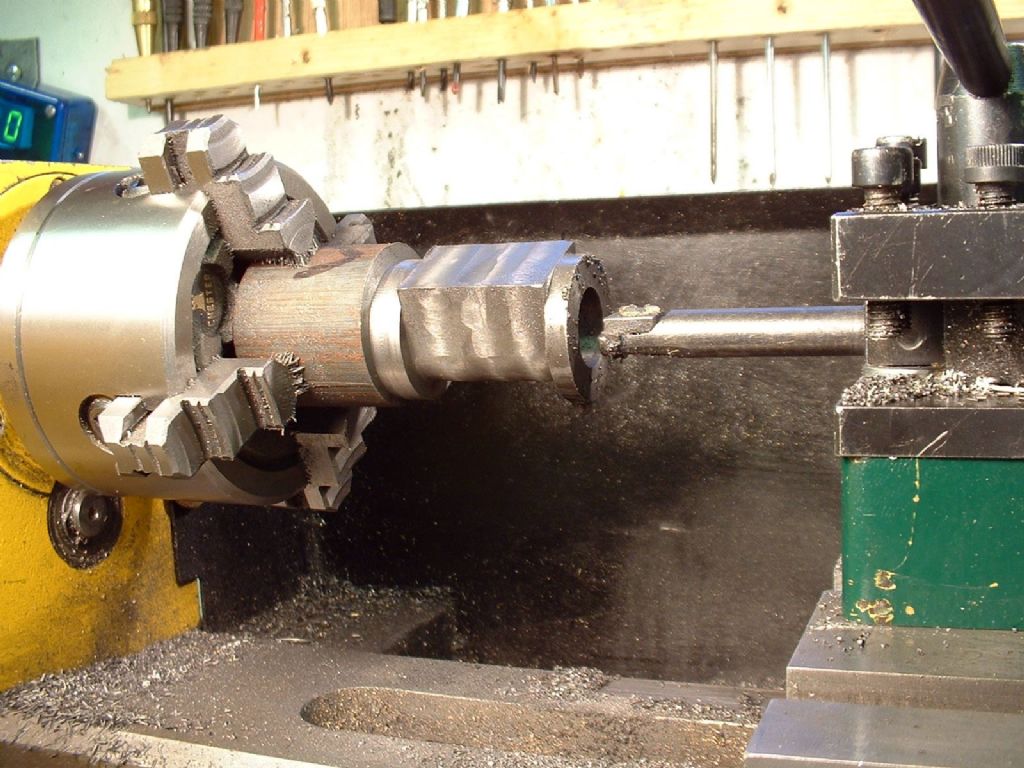 |
Magazine Locator
Want the latest issue of Model Engineer or Model Engineers' Workshop? Use our magazine locator links to find your nearest stockist!
Sign up to our Newsletter
Sign up to our newsletter and get a free digital issue.
You can unsubscribe at anytime. View our privacy policy at www.mortons.co.uk/privacy
Latest Forum Posts
- *Oct 2023: FORUM MIGRATION TIMELINE*
05/10/2023 07:57:11 - Making ER11 collet chuck
05/10/2023 07:56:24 - What did you do today? 2023
05/10/2023 07:25:01 - Orrery
05/10/2023 06:00:41 - Wera hand-tools
05/10/2023 05:47:07 - New member
05/10/2023 04:40:11 - Problems with external pot on at1 vfd
05/10/2023 00:06:32 - Drain plug
04/10/2023 23:36:17 - digi phase converter for 10 machines.....
04/10/2023 23:13:48 - Winter Storage Of Locomotives
04/10/2023 21:02:11 - More Latest Posts...
- View All Topics
Support Our Partners


Shopping Partners
Subscription Offer

Latest "For Sale" Ads
- Reeves** - Rebuilt Royal Scot by Martin Evans
by John Broughton
£300.00 - BRITANNIA 5" GAUGE James Perrier
by Jon Seabright 1
£2,500.00 - Drill Grinder - for restoration
by Nigel Graham 2
£0.00 - WARCO WM18 MILLING MACHINE
by Alex Chudley
£1,200.00 - MYFORD SUPER 7 LATHE
by Alex Chudley
£2,000.00 - More "For Sale" Ads...
Latest "Wanted" Ads
- D1-3 backplate
by Michael Horley
Price Not Specified - fixed steady for a Colchester bantam mark1 800
by George Jervis
Price Not Specified - lbsc pansy
by JACK SIDEBOTHAM
Price Not Specified - Pratt Burnerd multifit chuck key.
by Tim Riome
Price Not Specified - BANDSAW BLADE WELDER
by HUGH
Price Not Specified - More "Wanted" Ads...
Get In Touch!
Do you want to contact the Model Engineer and Model Engineers' Workshop team?
You can contact us by phone, mail or email about the magazines including becoming a contributor, submitting reader's letters or making queries about articles. You can also get in touch about this website, advertising or other general issues.
Click THIS LINK for full contact details.
For subscription issues please see THIS LINK.
Digital Back Issues


Donate

 Register
 Log-in
Model Engineer Magazine
- Percival Marshall
- M.E. History
- LittleLEC
- M.E. Clock

ME Workshop
- An Adcock
- & Shipley
- Horizontal
- Mill

Subscribe Now
- Great savings
- Delivered to your door

Pre-order your copy!
- Delivered to your doorstep!
- Free UK delivery!