Member postings for Peter G. Shaw
Here is a list of all the postings Peter G. Shaw has made in our forums. Click on a thread name to jump to the thread.
| Thread: Warco minimill OR SIEG Super X2 OR none of them ? |
| 12/03/2010 14:32:29 |
Hi MarcuSweden, Following your post and that of others on the X3 mill thread, i have had another look at my MiniMill controller board. It would seem that I do indeed have a KB board. From the KB website, I picked up the following: There seem to be two possible boards - KBLC and KBIC. I suspect the IC board is newer than the LC board. Also, KB state that from a set date, all their boards have a nine digit serial number on a sticky label. Mine does not have this label, but it does have a date 02-23-05 which is before KB started the 9 -digit scheme. Otherwise the connections, layout and physical design agree with both boards. I therefore think that mine is an LC board. Which all seems to suggest that the idea that the higher powered motors have a different controller, hence controller failure may be a thing of the past. (Fingers crossed.) Regards, Peter G. Shaw |
| 11/03/2010 11:25:22 |
Hi all, I'd just like to expand a little on what I have already said. Gear breakages. In my case these were teeth that snapped off, and although the smaller gear does have a tooth broken adjacent to the keyway, there does not seem to a crack. The same gear does have another two teeth broken off elsewhere. Dials. As I said, I have made out a suitable conversion chart that I can easily look up. The major problem is that whilst the graduations for the X and Y axes are marked as 0.02mm, there are 75 graduations to per revolution which makes for difficult counting. On top of that, the Z axis fine feed is marked as 0.025mm and has 60 graduations per revolution. Hence there is plenty of scope for getting it wrong. Hence the chart. So, all screws are the same pitch, 1.5mm which is itself an odd value. Wonder why they didn't do 2mm? I suppose 1mm might have been too fine. Electronics. I rather fancy that if mine fails, I will have to do a reverse engineering job on it to find out how it works, and then try for substitute components. I have to say that I am at one with Harold Hall on this, in that my lathe, a non-electronic beltchanging job will simply work, and work, and .... And could well be passed on to my grandchildren in years to come. However, an electronic failure could turn the MinimIll into an expensive doorstop - unless I, or some other amateur, can reverse engineer and repair. Professionally, it won't be worth it. <Rant mode on> Just like modern cars, having just forked out for an electronic diagnosis to find a blocked fuel filter!<Rant mode off>! (Sorry about that.) Regards, Peter G. Shaw |
| 10/03/2010 20:17:53 |
Hi folks, Well I had a look at my controller. Assuming that the largest devices are for the power output, then the mystery deepens even further. I have: 2 off A69108, and 3 off D8010L. The A69108 is a SCR (Silicon Controlled Rectifier whilst the D8010L is a rectifier both confirmed by the PCB legend. But... (there's always a but!) the D8010L has THREE legs which makes me wonder if it may be a dual diode. I did also find a reference to the Chester Conquest which also had two SCR's and three three-legged diodes. So, it looks as if my MiniMill does not have mosfets! Regards, Peter G. Shaw |
| 10/03/2010 11:01:41 |
Keith, I do wonder if your comment about owning a German made machine is the crux of the matter. Referring back to David White's articles in MEW, without looking them up, I seem to think he thought the German made machines were better. Of course, memory being what it is, I could be completely and utterly wrong. Nevertheless, I do believe the German machines in general are better put together than the Chinese. Nevertheless, as long as people are aware of what they are buying, and accept that the machines will need some fettling, then ok, they are probably reasonable. In my case, I do have a lot of work still to do - unfortunately temperature (the garage just doesn't get warm quickly enough!) and other jobs are against me! Regards, Peter G. Shaw |
| 09/03/2010 20:32:58 |
Keith, I have broken my gears. I was aware of this problem before I bought it and so I treated it with a certain amount of care. I find it interesting that Arc Euro Trade sell metal gears. Ok they are for the C3 lathe. But why? Somehow I doubt Arc Euro Trade would stock these items unless there was a proven need for them. One final point. When I rang Warco to obtain a replacement set, the storeman offered the opinion that they usually lasted longer than they had with me. This suggests to me that they do indeed break and that I had perhaps been unlucky that they broke so quick. As regards the electronics boards, there do seem to be a number of different power motors around - 350W, 470W, 550W and possibly more. Now it does seem to me that the original version was the 350W board. It also seems logical to me that the higher power motors will require higher power mosfets, so wouldn't it be logical to uprate them at the same time? Maybe I'm being too naive! You are right about the Z-axis backlash. I forgot about that. Regards, Peter. |
| 09/03/2010 20:02:27 |
Have a look at this thread on this forum: "Blown X1 Mill speed control". It has some information which may be of use. Little or no experience of Warco after sales service. When I broke the gear wheels, they posted replacements out immediately. I understand that ArcEuro stopped selling the X2 due to the high failure rate of the electronics board, and it was costing them too much. I understand that Machine Mart have a good spares catalogue, but that they do not sell individual components, just assemblies, ie you could get a new controller board, but not the individual transistors. The Clarke CMD300, sold by Machine Mart, looks similar, so they may have spares. Also, a company called Amadeal sells the XJ12-300 which looks to be identical to the MiniMill, so they may have spares. The spindle bearings are ball bearing types. On my machine the lower bearing is a 7206AC whilst the upper bearing is a 6206RZ . (They do look to be the same size.) I understand that changing to taper roller does improve matters, and I suspect that this will probably make it easier when changing the gears. (Especially if my experience with the original VW Beetle front wheel bearings is anything to go by.) I have to say that changing the gears was not perhaps the best thing to do for the bearings. So much so that when it happens again, I will probably change to taper rollers then. Regards, Peter G. Shaw ps I will have a look at the mosfets next time I go into the workshop and see if they do indeed have any numbers on them. Edited By Peter G. Shaw on 09/03/2010 20:04:47 |
| 09/03/2010 16:28:03 |
Hi, I have a Warco MiniMill. I will tell you what I know, my experiences and then leave the decision to you. I cannot comment on the Sieg Super X2. The MiniMill is not made by Sieg, although it does use the same basic idea and layout. It does use the same internal gears (see later). My MiniMill was made by Yangzhu Real Bull Machine Tool Co. Ltd. The impression I get is that there are a number of Chinese factories making machine tools to the same basic designs, but with small differences. About my mill. Some of the slides were/are in a very poor state and require work on them to improve them. David White has produced a number of articles in MEW on improving the Sieg X0 which seem equally applicable to the X2 and equivalent. He has also produced an article on the Weiss WMD25LV machine in which there is a photograph of the internal gears. This photo looks to be identical to the MiniMill. White also says that he found lots of casting sand etc on the Weiss. So did I on the MiniMill. The Sieg X2 (350watt motor) is well known for two problems. These are the breakage of the plastic internal gears, and the failure of the electronic control board. I have experienced the gear failure on the MiniMill, but not (yet) any electronic failure, however, the fact that there is a more powerful motor may indicate that the electronics have been uprated and thus eliminated the problem. At least that is what I hope. In respect of the internal gears, these can be difficult to change, however, Arc Euro Trade do a set of metal gears, supposedly for the Sieg C3 lathe (I think), but advertised by them as suitable for the X2 machine, and I can confirm that they will fit the MiniMill. Another option to overcome gear breakages is to convert to belt drive. There are kits available which may or may not fit the MiniMill. Claimed advantages are that a higher speed may be obtained and the machine is quieter. On my machine, I could not get the fine vertical movement to work. The handbook didn't mention it, and did not even have the correct information about switching on. Fortunately, I found a downloadable manual produced by LittleMachineShop.com which explained about the fine vertical movement. I discovered that the fine feed mechanism was binding to such an extent that it was unusable. Careful adjustment made it work. The MiniMill uses a counterbalancing spring to take the weight of the head. On mine the spring has lost some of it's tension, but that may be because of something I did. I fond the dials difficult to understand. They are not calibrated in anything recognisable, so I made a conversion label which I have stuck to the machine. Also, the variable speed is not calibrated. Again I have made an approximate speed label using a cycle computer to measure the speeds. I suggest you hunt around the forums for the X2. You will find a lot of information on improving the X2 series of mills (which will include the MiniMill) and on setting them up, eg vertical alignment both back to front, side to side, and the alignment of the travelling head. Also information on stiffening the vertical column. David White has a novel method of doing this as well. The Warco MiniMill has a larger table than the Sieg X2. I can't think of anything else. Good luck in your quest. Peter G. Shaw |
| Thread: Milling/Drilling machine advice |
| 07/03/2010 21:22:05 |
Hi, The Sealey machine is essentially a Sieg X2. Ok, I've no doubt that Sealey will deny it, just as Warco deny that their MiniMill is a X2. Warco is actually correct in that their machine is not made by Sieg, however, it is "strange" that it looks similar to one, has the same facilities as one, and even breaks gears as one. In fact, it seems as if the same basic design is used by a number of Chinese factories. So, I would suggest that the Sealey may well have the same known problems as the X2, ie a propensity to break gears and a possibly fault prone electronics. Of course, Sealey may be using better components, in which case fair enough. Now the X2 series of mills can be retrofitted with a belt drive - it may be possible to buy a kit which fits direct, or it may have to be specially made. It all depends on the originating factory. The belt drive allows for higher speeds and is quieter, so I understand. I note that the Sealey uses a 350W motor. May I point out that Warco and Amadeal supply similar machines with a 550W motor. Also, the Warco has a larger table than the standard X2. I don't know about the Sealey. Finally, have you looked at the ArcEuro X1 machine with the long bed? In terms of size it is only very slightly smaller than the X2 type, hence may do for you. To my mind, though, the motor power at 150W may be a tad small, but then I've no experience of it. Having said that, the machine is available at a lot of places so some people must be buying it. Regards, Peter G. Shaw ps. I thought I had better add that I have a Warco MiniMill, so my comments re the gears are based on personal experience. Also, Arc Euro Trade sell replacement METAL gears ostensibly for the C3 lathe I think, but according to them, and to my personal knowledge, identical to the plastic ones used in the X2 and the Warco MiniMill. I should also say that I have not had any problems electronically. Maybe the uprated motor has caused an uprated/improved electronic control. Edited By Peter G. Shaw on 07/03/2010 21:26:19 |
| Thread: Drawing projection, first or third? |
| 28/02/2010 12:01:37 |
A bit tongue in cheek here. Why, oh why, does everyone have to bow down to AutoCad. Is it because it was the first program that really worked? Or was because some big firm with an interest pushed it? By all accounts not only is Autocad expensive, but it is difficult to understand, as is, in my opinion, TurboCad. And yet, the program I use, Design Cad 3D Max is reasonably cheap, dead easy to use and understand and it is capable of exporting data in a variety of formats, including Autocad dwg formats. Circlip mentioned Lotus 1-2-3. This leads me on to another hobby horse of mine. Until recently I used the Lotus suite of programs in preference to the expensive Microsoft Works or Office programs. Unfortunately, for a variety of reasons, the majority of people use the Microsoft offerings, and when exporting data almost always do so in Microsoft's proprietery format, eg .xls or .doc etc. Which means that I have now had to switch over to Open Office as these programs are compatible with the Microsoft formats as otherwise I cannot exchange data. If people were to realise that there are alternative universal formats which any program can use, then the likes of Microsoft would lose their stranglehold on the market which can only be a good thing. Similarly, when I sent a drawing into the Editor, I have to use one of a small number of specific formats, at least one of which was an Autocad format. Now I have to say that I don't know what, or even if, there is a universal drawing format, but it seems wrong to me to enforce formats which are proprietary. It also seems wrong to me to hold up one very expensive program as the ultimate standard to aim for. One final point about line thicknesses. Although I usually only use the one, my program is capable of producing many thicknesses although I have never tried it. Regards, Peter G. Shaw |
| 26/02/2010 12:08:21 |
So, given that I am neither a trained draftsman nor a trained engineer, where does that leave me? I have already said that I find 3rd angle rather more "natural" than 1st angle. I have also read, and try to understand and apply Tubal Cain's writings in Workshop Drawing, WSP no 13. I also have Brown's CAD for Model Engineers, WSP no. 29, which frankly isn't that much help because my CAD isn't the same as his. I know, for example, that partly due to the constraints of the CAD program, and the VDU, I do not do things as TC would wish, a good example being the use of heavier lines for the outline. I actually draw at minimum width because using the VDU, a heavy black line varies (and gets larger) if I zoom into expand a part of the drawing whereas a minimum thickness line remains the same no matter what the zoom. Also, I show dimensions, again due to the vagaries of the CAD, in different places to avoid clutter. Does this mean that anything I submit to the magazine will have to be completely redrawn? I think the answer has to be that for "our" purposes, we have to understand that "our" people will have the ability to be able to make sense of what is drawn, and whilst it may be "wrong" to the trained draftsman/engineer as long as it is clear and unambiguous then surely that is the most important factor. Let's face it, whilst on the shop floor, drawings will have to be, as Circlip says, suitable for untrained monkeys whose only interest is the brown envelope at the weekend, "we", as amateurs, are doing it for our own interest, and thus will be prepared to invest our time in understanding the drawings, even if they are not to the relevant BS/ISO. Regards, Peter G. Shaw |
| 24/02/2010 13:27:14 |
Well now, as a rank amateur with no training on drafting other than what I was told (ie didn't particularly learn!) at secondary school, I have had to teach myself. Tubal Cain, in his book Workshop Drawing (WSP13) says that he finds 1st angle instinctive and always uses it. I have to say that I don't find it instinctive, rather I find 3rd angle instinctive in that to me it makes absolute sense that when drawing a view at right angles to the main view, that view should be as if I was looking at the relevant side, and placed at the same side. (Sorry if that doesn't make sense - I know what I mean!) I do agree though, that what is extremely important is to show the appropriate 1st/3rd angle symbol to avoid ambiguity. Regards, Peter G. Shaw ps. Especially to Circlip. I use a CAD program. Occasionally I may do a pencil sketch, but if you could see the poor quality of my handwork, you would immediately realise why I use the CAD program. I have no doubt that I could learn to do proper pencil & paper drawings, but at my stage in life I am simply not interested in doing so when the CAD program does it so much more easily, and allows me to develop my ideas without having to use an eraser and shield. |
| Thread: Making a screwcutting tap |
| 23/02/2010 13:07:37 |
Thanks for that Michael, I'll bear it in mind. Peter |
| 22/02/2010 16:37:40 |
Hi Ramon, Many thanks. Now, I WAS going to buy a proper UNF tap, but now I've decided to get some more silver steel instead and have another go. Watch this space.... Regards, Peter |
| Thread: Starting from scratch |
| 20/02/2010 21:25:06 |
Don't go for a Unimat 1 - it's more of a toy than a real piece of engineering kit. Although I am aware that it is now possible to buy metal parts rather than the original plastic parts. And yes, I bought one before getting a Hobbymat which I then P/X'd for the present Warco 220/Mashstroy C210T. Vertical slides are ok but limited in their capacity. Also, it is necessary to ensure that the lathe slides are themselves in tip-top condition due to the vibration generated when milling. I had one with the Hobbymat and it was reasonable useful, however with the 220 it wasn't until I tightened everything up AND used a direct collet in the headstock taper to hold the milling cutter. Then, and only then did it start to become reasonable. But the lack of size still remains a limiting factor. I now have a milling machine. Regards, Peter G. Shaw |
| Thread: Making a screwcutting tap |
| 20/02/2010 21:10:00 |
Nice pictures Ramon. That's a lot better than reams of reading as now I can see what others have done and I now have something to aim for instead of blindly aiming in the dark. Many thanks. Now, if I can work out how to do it, I am about to post two pictures of the countersink which show the "inclusions" (for want of a better word). Your thoughts would be most welcome, especially if it's due to overheating. 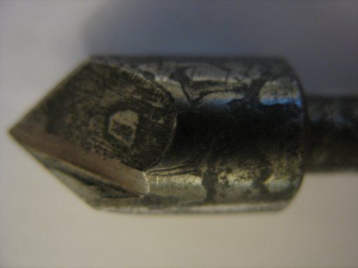 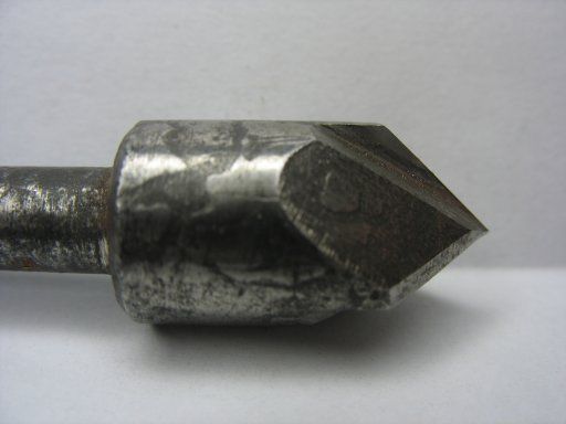  Hooray, done it! Which just goes to show that one CAN teach an old dog new tricks! Regards, Peter G. Shaw Ok edit no.1 Apologies for the quality of the photos. The camera is a Canon Powershot A610 used in Auto mode, Macro, and flash turned off. And handheld! Photographer I ain't. Edited By Peter G. Shaw on 20/02/2010 21:12:45 |
| 20/02/2010 16:54:27 |
Lots of very interesting stuff here. Many thanks gents. Also, a big thankyou to Richmond for locking the other thread. As I said in that thread, it was my fault, and I'm still not sure what I did. Anyway... Ramon, I think the missing posts are in the other thread. Now, an auxiliary question which follows on from what Ramon was saying about colours and overheating. Both the tap, and the countersink showed definite signs of, dare I say, what looked like "inclusions". These appeared after the initial heating and cooling. Does this suggest that I have overheated the steel? Regards, Peter G. Shaw |
| 20/02/2010 12:13:09 |
Hi Meyrick & Ramon, Reading both threads - I wish there was some way of removing a duplicate, moderators please note - I note that you did not bother tempering, and screwcut slightly large. Screwcutting slightly large was something I had thought about but have no idea how much larger. May I ask how much larger? I take the point about the cutting edges tempering softer. The tool-to-be was left mounted in the chuck for all operations. My mandrel does have 12 equally spaced holes around it so indexing to three or four is dead easy and my original intentios was to do three, however the grinding operation was not exactly good, so we stuck with one. The minidrill grinder was mounted on the vertical slide so we got the three axes of movement. We angled the grinder and mounted it on centre expecting to produce an undercut - then we realised that this wouldn't work, hence the file. It did occur to me that perhaps using a milling cutter might have been better, but I haven't yet got suitable facilities. We were using carbide tools for the initial turning, not round nose, but one with a sharpish point with the point just taken off. Even so, I find the damn things chip far too easily. (When I finally grind these things down to a minimum size I will replace with either HSS, or possibly even carbon steel.) The actual thread cutting was done with the very first tool I ever made - ¼" square carbon steel - made about 20 years ago and which does seem to work quite well although we noticed that it does now need fettling. We did not use any coolant for the initial turning, but we did use some when screwcutting, which was done using a mandrel handle - 125rpm is a tad too fast for me when screwcutting about 1"! Using oil to cool. Will ordinary clean engine oil do? Sand for tempering. Ordinary builders sand (sharp sand)? Many thanks so far. Peter G. Shaw |
| 19/02/2010 21:50:02 |
Oh dear, I've managed to enter it twice. Can I suggest that any answeres should appear on this particular thread. My apologies for this cock-up. Peter G. Shaw |
| Thread: Making a screwcutting tap |
| 19/02/2010 21:48:38 |
Oh dear, I've managed to enter it twice. Please accept my apologies and ignore this entry. Peter G. Shaw |
| Thread: Making a screwcutting tap |
| 19/02/2010 21:47:24 |
| Hi folks, A recent project with my grandson resulted in an attempt to make a UNF 3/8 24tpi tap out of silver steel. Lots of things went wrong but we did eventually manage to cut a thread in a piece of aluminium. This is what we did, along with what we know we did wrong, but I'd like to ask, for the future that is, for any other thoughts. I should point out that one of the reasons for this project was to let the grandson do as much as possible, and to see the rest. First we took a piece of half-inch silver steel and turned it down to 3/8ths. Unfortunately the only way that we seem to be able to get a smooth, and hence accurately measureable, surface is to rough turn first, then finish turn using high speed and slowest possible manual feed. So of course, the finished surface ended up slightly less than it should have been, and a repeat attempt the same. As it happens, the device that was intended to screw in was itself slightly less, so we continued. Next we screwcut. In retrospect we should have produced the taper first, so that was yet another mistake. Anyway, I've never had much luck with trying to calculate depths of cut etc for screwcutting and so had to resort to using a nut as a test piece. So this is what we did, and produced a thread. At this point we tapered the job. That was ok, we used 8° included as per Tubal Cain's instructions. Then we tried to create a cutting edge using a minidrill with a grinding disc in the chuck. We had looked at other similar sized taps and realized that we needed to produce an undercut under the cutting edge and so we tried to set the minidrill appropriately. We weren't particularly successful and finished up using a file to try to improve matters. Thoughts on how to do this would be most appreciated. Also on how to produce, say, three cutting edges. Having got this far we then hardened it. Ok we didn't bother with the one hour per inch as per Tubal Cain and others, but neverthe less got it very hot and then quickly dunked it in cold water. This was followed by tempering to light straw, although here again I suspect we may have heated it too quick and possibly had some of it nearer brown. We tried it out on a piece of aluminium, slowly increasing the drill size until we could get it to cut, which it did after a fashion. After cleaning up, we found that the original device it was meant for could actually be screwed in, albeit tightly, so in that respect it was more or less successful. Grandson, by the way, was absolutely delighted with the result, even though it wasn't perfect. To him, it was the act of screwcutting in the lathe and then hardening and tempering the silver steel, none of which he has ever seen before. So, thoughts please. Peter G. Shaw |
Magazine Locator
Want the latest issue of Model Engineer or Model Engineers' Workshop? Use our magazine locator links to find your nearest stockist!
Sign up to our Newsletter
Sign up to our newsletter and get a free digital issue.
You can unsubscribe at anytime. View our privacy policy at www.mortons.co.uk/privacy
Latest Forum Posts
- *Oct 2023: FORUM MIGRATION TIMELINE*
05/10/2023 07:57:11 - Making ER11 collet chuck
05/10/2023 07:56:24 - What did you do today? 2023
05/10/2023 07:25:01 - Orrery
05/10/2023 06:00:41 - Wera hand-tools
05/10/2023 05:47:07 - New member
05/10/2023 04:40:11 - Problems with external pot on at1 vfd
05/10/2023 00:06:32 - Drain plug
04/10/2023 23:36:17 - digi phase converter for 10 machines.....
04/10/2023 23:13:48 - Winter Storage Of Locomotives
04/10/2023 21:02:11 - More Latest Posts...
- View All Topics
Support Our Partners


Shopping Partners
Subscription Offer

Latest "For Sale" Ads
- Reeves** - Rebuilt Royal Scot by Martin Evans
by John Broughton
£300.00 - BRITANNIA 5" GAUGE James Perrier
by Jon Seabright 1
£2,500.00 - Drill Grinder - for restoration
by Nigel Graham 2
£0.00 - WARCO WM18 MILLING MACHINE
by Alex Chudley
£1,200.00 - MYFORD SUPER 7 LATHE
by Alex Chudley
£2,000.00 - More "For Sale" Ads...
Latest "Wanted" Ads
- D1-3 backplate
by Michael Horley
Price Not Specified - fixed steady for a Colchester bantam mark1 800
by George Jervis
Price Not Specified - lbsc pansy
by JACK SIDEBOTHAM
Price Not Specified - Pratt Burnerd multifit chuck key.
by Tim Riome
Price Not Specified - BANDSAW BLADE WELDER
by HUGH
Price Not Specified - More "Wanted" Ads...
Get In Touch!
Do you want to contact the Model Engineer and Model Engineers' Workshop team?
You can contact us by phone, mail or email about the magazines including becoming a contributor, submitting reader's letters or making queries about articles. You can also get in touch about this website, advertising or other general issues.
Click THIS LINK for full contact details.
For subscription issues please see THIS LINK.
Digital Back Issues


Donate

 Register
 Log-in
Model Engineer Magazine
- Percival Marshall
- M.E. History
- LittleLEC
- M.E. Clock

ME Workshop
- An Adcock
- & Shipley
- Horizontal
- Mill

Subscribe Now
- Great savings
- Delivered to your door

Pre-order your copy!
- Delivered to your doorstep!
- Free UK delivery!